1
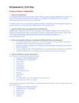
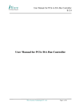
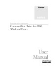
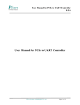
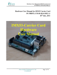
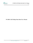
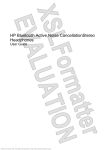
Hardware User Manual for iMX51 iW-PRDRB-UM-01-R2.0-REL1.2 Hardware User Manual for iMX51 R 2.0 3rd Dec, 2010 iMX51-Carrier Card Hardware User Manual iWave Systems Technologies Pvt. Ltd. (Confidential) Page 1 of 36 Hardware User Manual for iMX51 iW-PRDRB-UM-01-R2.0-REL1.2 DOCUMENT REVISION HISTORY Revision Date Change Description Author 2.0 –REL1.0 2nd Aug 2010 USB Host image updated SK Rest same as R1.0 REL 1.1 2.0 –REL1.1 3rd Dec 2010 ATK Flash Address for Diagnostic, SK Linux, Android and WinCE binaries updated. th 2.0 –REL1.2 24 Feb 2011 1. Change the SD1 Host to SD2, RG 2.USB HOST to USB OTG 3.Added Power Rating For Supply 4. GUI Diagnostic Updated PROPRIETARY NOTICE: This document contains proprietary material for the sole use of the intended recipient(s). Do not read this document further if you are not the intended recipient. Any review, use, distribution or disclosure by others is strictly prohibited. If you are not the intended recipient (or authorized to receive for the recipient), you are hereby notified that any disclosure, copy or distribution or use of any of the information contained within this document is STRICTLY PROHIBITED. Thank you. “iWave Systems Tech. Pvt. Ltd.” iWave Systems Technologies Pvt. Ltd. (Confidential) Page 2 of 36 Hardware User Manual for iMX51 iW-PRDRB-UM-01-R2.0-REL1.2 TABLE OF CONTENTS 1 INTRODUCTION ...............................................................................................................................................6 2 PURPOSE .........................................................................................................................................................6 SCOPE .............................................................................................................................................................6 GLOSSARY ......................................................................................................................................................6 HARDWARE DETAILS.....................................................................................................................................7 IMX51-CARRIER CARD CONNECTOR DETAILS ............................................................................................... 7 HARDWARE SETUP DETAILS ...........................................................................................................................9 2.2.1 Power supply Connecting procedure .....................................................................................................9 2.2.2 Serial cable connecting procedure ...................................................................................................... 10 2.2.3 USB OTG (as HOST) connecting procedure ....................................................................................... 11 2.2.4 SD2/MMC Connecting Procedure ....................................................................................................... 12 2.2.5 Micro SD Connecting Procedure ......................................................................................................... 13 2.2.6 Audio In cable connecting procedure .................................................................................................. 14 2.2.7 Audio Out cable connecting procedure ............................................................................................... 15 2.2.8 VGA Cable Connecting Procedure ...................................................................................................... 16 2.2.9 TV In connecting Procedure (Composite video Input)......................................................................... 17 2.2.10 Ethernet Cable Connecting Procedure ................................................................................................ 18 2.2.11 USB Host 1 Connecting Procedure ..................................................................................................... 19 3 POWER ON ....................................................................................................................................................... 20 4 ATK USER MANUAL ...................................................................................................................................... 26 5 HYPERTERMINAL SETUP .............................................................................................................................. 20 BOOT OS FROM DIAGNOSTICS ...................................................................................................................... 24 INSTALLING ADVANCED TOOL KIT .............................................................................................................. 26 INITIAL SETUP OF ADVANCED TOOL KIT ...................................................................................................... 26 FLASH PROGRAMMING THE BOOT CODE ...................................................................................................... 28 FLASH PROGRAMMING THE LINUX KERNEL IMAGE ...................................................................................... 29 FLASH PROGRAMMING THE LINUX INITRD IMAGE ........................................................................................ 31 FLASH PROGRAMMING THE ANDROID KERNEL IMAGE ................................................................................. 32 FLASH PROGRAMMING THE ANDROID INITRD IMAGE ................................................................................... 33 FLASH PROGRAMMING THE WINCE IMAGE .................................................................................................. 34 FREQUENTLY ASKED QUESTIONS (FAQ): .................................................................................................... 35 TECHNICAL SUPPORT ................................................................................................................................. 36 iWave Systems Technologies Pvt. Ltd. (Confidential) Page 3 of 36 Hardware User Manual for iMX51 iW-PRDRB-UM-01-R2.0-REL1.1 List of Figures FIGURE 1:IMX51-CARRIER CARD CONNECTOR DETAILS ................................................................ 8 FIGURE 2: IMX51-CARRIER CARD POWER CONNECTION ................................................................ 9 FIGURE 3: IMX51-CARRIER CARD SERIAL PORT CONNECTION ..................................................... 10 FIGURE 4:USB CONNECTION ........................................................................................................ 11 FIGURE 5:SD2 CONNECTION .......................................................................................................... 12 FIGURE 6:MICRO SD CONNECTION ................................................................................................ 13 FIGURE 7:AUDIOIN CONNECTION .................................................................................................. 14 FIGURE 8:AUDIOOUT CONNECTION ............................................................................................... 15 FIGURE 9:VGA CABLE CONNECTION ............................................................................................ 16 FIGURE 10:RCA CABLECONNECTION ............................................................................................ 17 FIGURE 11:EHERNET CONNECTION ................................................................................................ 18 FIGURE 12:USB HOST1 CONNECTION ........................................................................................... 19 FIGURE 13:HYPERTERMINAL SETTINGS .......................................................................................... 22 FIGURE 14:ENABLE ECHO TYPED CHARACTERS ............................................................................. 23 FIGURE 15: GUI MAIN MENU IN LCD ........................................................................................... 24 FIGURE 16: DIAGNOSTIC MENU IN HYPER TERMINAL .................................................................... 25 iWave Systems Technologies Pvt. Ltd. (Confidential) Page 4 of 36 Hardware User Manual for iMX51 iW-PRDRB-UM-01-R2.0-REL1.1 List of Tables TABLE 1:GLOSSARY ............................................................................................................................... 6 iWave Systems Technologies Pvt. Ltd. (Confidential) Page 5 of 36 Hardware User Manual for iMX51 iW-PRDRB-UM-01-R2.0-REL1.1 1 Introduction Purpose The purpose of this document is to explain the procedure about the user interface, Power ON procedure and ATK tool kit usage for iMX51-Carrier Card. Scope This document describes the Hardware details, Power-on procedure and setting up Serial communication with PC/Laptop. This document also explains usage procedure for ATK tool kit. Glossary Table 1:Glossary Acronyms CSPI FFS GUI LCD DDR MMC PC PMIC RAM RTC TV UART USB UUE Description. Configurable Serial Peripheral Interface Flash File System Graphic User interface Liquid Crystal Display Double Data Rate Multi Media Card Personal computer Power management Integrated circuit Random Access memory Real time Clock Television Universal Asynchronous Receiver Transmitter Universal Serial Bus Unix to Unix Encoded file iWave Systems Technologies Pvt. Ltd. (Confidential) Page 6 of 36 Hardware User Manual for iMX51 iW-PRDRB-UM-01-R2.0-REL1.1 2 Hardware Details iMX51-Carrier Card Connector details iWave Systems Technologies Pvt. Ltd. (Confidential) Page 7 of 36 Hardware User Manual for iMX51 iW-PRDRB-UM-01-R2.0-REL1.1 Figure 1:iMX51-Carrier Card Connector Details iWave Systems Technologies Pvt. Ltd. (Confidential) Page 8 of 36 Hardware User Manual for iMX51 iW-PRDRB-UM-01-R2.0-REL1.1 Hardware Setup Details 2.2.1 Power supply Connecting procedure Insert the power plug of the power supply into the power jack of the iMX51-Carrier Card as below. Power Rating: 5V input with 2.5A. Figure 2: iMX51-Carrier Card Power Connection iWave Systems Technologies Pvt. Ltd. (Confidential) Page 9 of 36 Hardware User Manual for iMX51 iW-PRDRB-UM-01-R2.0-REL1.1 2.2.2 Serial cable connecting procedure 1. The serial cable has DB9 connector (Female type) at both end. 2. Insert DB9 of the serial cable to PC/Laptop COM port. 3. Connectt the other end of the serial cable to iMX51 carrier board serial port connector as shown below. Figure 3: iMX51-Carrier Card Serial Port Connection iWave Systems Technologies Pvt. Ltd. (Confidential) Page 10 of 36 Hardware User Manual for iMX51 iW-PRDRB-UM-01-R2.0-REL1.1 2.2.3 USB OTG (as HOST) connecting procedure Insert the USB in the USB connector as shown below. Figure 4:USB Connection iWave Systems Technologies Pvt. Ltd. (Confidential) Page 11 of 36 Hardware User Manual for iMX51 iW-PRDRB-UM-01-R2.0-REL1.1 2.2.4 SD2/MMC Connecting Procedure Insert the SD Memory card in the SD1 slot as shown below. Figure 5:SD2 Connection iWave Systems Technologies Pvt. Ltd. (Confidential) Page 12 of 36 Hardware User Manual for iMX51 iW-PRDRB-UM-01-R2.0-REL1.1 2.2.5 Micro SD Connecting Procedure Insert the Micro SD Memory card in the MicroSD slot as shown below. Figure 6:Micro SD Connection iWave Systems Technologies Pvt. Ltd. (Confidential) Page 13 of 36 Hardware User Manual for iMX51 iW-PRDRB-UM-01-R2.0-REL1.1 2.2.6 Audio In cable connecting procedure Insert the Audio IN jack into the Audio in connector as shown below. Figure 7:AudioIn Connection iWave Systems Technologies Pvt. Ltd. (Confidential) Page 14 of 36 Hardware User Manual for iMX51 iW-PRDRB-UM-01-R2.0-REL1.1 2.2.7 Audio Out cable connecting procedure Insert the Audio OUT jack into the Audio out connector as shown below. Figure 8:AudioOut Connection iWave Systems Technologies Pvt. Ltd. (Confidential) Page 15 of 36 Hardware User Manual for iMX51 iW-PRDRB-UM-01-R2.0-REL1.1 2.2.8 VGA Cable Connecting Procedure Insert the VGA cable into the VGA OUT(DB15) connector as shown below. Figure 9:VGA Cable Connection iWave Systems Technologies Pvt. Ltd. (Confidential) Page 16 of 36 Hardware User Manual for iMX51 iW-PRDRB-UM-01-R2.0-REL1.1 2.2.9 TV In connecting Procedure (Composite video Input) Insert the RCA cable in to the TV in connector as shown below. Figure 10:RCA CableConnection iWave Systems Technologies Pvt. Ltd. (Confidential) Page 17 of 36 Hardware User Manual for iMX51 iW-PRDRB-UM-01-R2.0-REL1.1 2.2.10 Ethernet Cable Connecting Procedure Insert the Ethernet cable into the RJ-45 connector as shown below. Figure 11:Ehernet Connection iWave Systems Technologies Pvt. Ltd. (Confidential) Page 18 of 36 Hardware User Manual for iMX51 iW-PRDRB-UM-01-R2.0-REL1.1 2.2.11 USB Host 1 Connecting Procedure Insert the USB device (ex : USB Pen Drive) to the USB Host1 connector (Standard Type A) as shown below. Figure 12:USB Host1 Connection iWave Systems Technologies Pvt. Ltd. (Confidential) Page 19 of 36 Hardware User Manual for iMX51 iW-PRDRB-UM-01-R2.0-REL1.1 3 Power On HyperTerminal Setup 1. Insert one end of the serial cable to PC/Laptop COM port (DB9 Male Connector.) 2. Connect the other end of the serial cable to serial connector in the Board as shown in Figure 3 3. Open the HyperTerminal on the PC/Laptop as mentioned below 4. Go to Start -> Programs -> Accessories -> Communication -> Hyperterminal on the host PC/Laptop. 5. In hyperterminal,Go to Files ->Properties 6. Select COM1 or COM2 port depending on which port you have connected the serial cable.This is shown below. iWave Systems Technologies Pvt. Ltd. (Confidential) Page 20 of 36 Hardware User Manual for iMX51 iW-PRDRB-UM-01-R2.0-REL1.1 7. Now Click Configure button and do Port Settings as below.. Bits per Second (Baud Rate) :115200 Data bits :8 Parity :None Stop Bits :1 Flow Control :None iWave Systems Technologies Pvt. Ltd. (Confidential) Page 21 of 36 Hardware User Manual for iMX51 iW-PRDRB-UM-01-R2.0-REL1.1 Figure 13:Hyperterminal settings 8. Go to File -> Properties -> Settings ->ASCII Setup. 9. Now Select„Echo typed characters locally‟ has to be enabled as shown below. 10. Go to Call -> Call to connect. 11. If you want to disconnect, Go to Call -> Disconnect. iWave Systems Technologies Pvt. Ltd. (Confidential) Page 22 of 36 Hardware User Manual for iMX51 iW-PRDRB-UM-01-R2.0-REL1.1 Figure 14:Enable Echo typed characters iWave Systems Technologies Pvt. Ltd. (Confidential) Page 23 of 36 Hardware User Manual for iMX51 iW-PRDRB-UM-01-R2.0-REL1.1 Boot OS from Diagnostics 1. Power the board, the below Menu will display in LCD Figure 15: GUI Main Menu in LCD 2. 3. Select the OS type and Memory (SD or FLASH) to boot OS, through LCD Touch panel. To get Diagnostic menu in hyper terminal, press any key from key board. The below menu will display in hyper terminal. iWave Systems Technologies Pvt. Ltd. (Confidential) Page 24 of 36 Hardware User Manual for iMX51 iW-PRDRB-UM-01-R2.0-REL1.1 Figure 16: Diagnostic Menu In hyper terminal 4. Select G option from hyper terminal to get GUI Main Menu in LCD. iWave Systems Technologies Pvt. Ltd. (Confidential) Page 25 of 36 Hardware User Manual for iMX51 iW-PRDRB-UM-01-R2.0-REL1.1 4 ATK User Manual Installing Advanced Tool Kit 1. Install “FSL_ATK_TOOL_WINS_STD_INSTALL_1_67.exe” setup in Windows PC (PC must have COM port or USB to serial convertor). Initial Setup of Advanced Tool Kit 1. Connect serial port from PC to i.MX 51 Processor board debug serial port. 2. Set the Bootstrap mode in the Processor board as mentioned in picture below (push both switches to ON position for bootstrap). iWave Systems Technologies Pvt. Ltd. (Confidential) Page 26 of 36 Hardware User Manual for iMX51 iW-PRDRB-UM-01-R2.0-REL1.1 3. Run the Open Advanced Toolkit application by double clicking the “Advanced Tool Kit V1.67” located in Desktop. 4. In Device Setting select the i.MX CPU as iMX51 TO2. 5. In Host Setting, select Communication channel as “Serial Port” and select the COM port. For example, select COM1 Port. 6. Click Next to Continue 7. Select Flash Tool and Click Go button. iWave Systems Technologies Pvt. Ltd. (Confidential) Page 27 of 36 Hardware User Manual for iMX51 iW-PRDRB-UM-01-R2.0-REL1.1 Flash Programming the Boot Code 1. In the next screen select below things. 2. Select Flash model as Custom model. 3. Click Browse button (under Flash model) and Select the given Binary File (“mx51to2_nand.bin”). 4. In Operation type Select Program. 5. In Operation settings, type Address as “0”. iWave Systems Technologies Pvt. Ltd. (Confidential) Page 28 of 36 Hardware User Manual for iMX51 iW-PRDRB-UM-01-R2.0-REL1.1 6. Click Browse button (Under image) and select the image file (“imx51_diag.bin”). 7. Click Program button. 8. Next zImage has to be programmed. Flash Programming the Linux Kernel Image 1. In the next screen select below things. iWave Systems Technologies Pvt. Ltd. (Confidential) Page 29 of 36 Hardware User Manual for iMX51 iW-PRDRB-UM-01-R2.0-REL1.1 2. Select Flash model as Custom model. 3. Click Browse button (under Flash model) and Select the given Binary File (“mx51to2_nand.bin”). 4. In Operation type Select Program. 5. In Operation settings, type Address as “300000”. 6. Click Browse button(Under image) and select the image file (“zImage”). 7. Click Program button. iWave Systems Technologies Pvt. Ltd. (Confidential) Page 30 of 36 Hardware User Manual for iMX51 iW-PRDRB-UM-01-R2.0-REL1.1 8. Next initrd has to be programmed. Flash Programming the Linux initrd Image 1. In the next screen select below things. 2. Select Flash model as Custom model. 3. Click Browse button (under Flash model) and Select the given Binary File (“mx51to2_nand.bin”). 4. In Operation type Select Program. 5. In Operation settings, type Address as “600000”. 6. Click Browse button (Under image) and select the image file (“initrd.gz”). 7. Click Program button. iWave Systems Technologies Pvt. Ltd. (Confidential) Page 31 of 36 Hardware User Manual for iMX51 iW-PRDRB-UM-01-R2.0-REL1.1 Flash Programming the Android Kernel Image 9. In the next screen select below things. 10. Select Flash model as Custom model. 11. Click Browse button (under Flash model) and Select the given Binary File (“mx51to2_nand.bin”). 12. In Operation type Select Program. 13. In Operation settings, type Address as “E00000”. 14. Click Browse button(Under image) and select the image file (“zImage”). 15. Click Program button. iWave Systems Technologies Pvt. Ltd. (Confidential) Page 32 of 36 Hardware User Manual for iMX51 iW-PRDRB-UM-01-R2.0-REL1.1 16. Next initrd has to be programmed. Flash Programming the Android initrd Image 8. In the next screen select below things. 9. Select Flash model as Custom model. 10. Click Browse button (under Flash model) and Select the given Binary File (“mx51to2_nand.bin”). 11. In Operation type Select Program. 12. In Operation settings, type Address as “1100000”. 13. Click Browse button (Under image) and select the image file (“initrd.gz”). 14. Click Program button. iWave Systems Technologies Pvt. Ltd. (Confidential) Page 33 of 36 Hardware User Manual for iMX51 iW-PRDRB-UM-01-R2.0-REL1.1 Flash Programming the WinCE Image 15. In the next screen select below things. 16. Select Flash model as Custom model. 17. Click Browse button (under Flash model) and Select the given Binary File (“mx51to2_nand.bin”). 18. In Operation type Select Program. 19. In Operation settings, type Address as “1900000”. 20. Click Browse button (Under image) and select the image file (“NK.bin”). 21. Click Program button. iWave Systems Technologies Pvt. Ltd. (Confidential) Page 34 of 36 Hardware User Manual for iMX51 iW-PRDRB-UM-01-R2.0-REL1.1 Frequently Asked Questions (FAQ): 1. What can be done if bootstrap mode is not detected message displayed in ATK toolkit ? <Answer> There may be three of reasons a. Check whether COM port is selected properly? b. Check whether board is set in bootstrap mode (as explained in “Figure 1 Bootstrap mode settings”) c. If both options are not helping, power off board and power on again. 2. What can be done If flash programming is getting failed(for any reason) half the way ? <Answer> Repeat the flash programming procedure for particular image once again. 3. What should I do “COM port is already in use message is displayed” ? <Answer> Check any program is using COM port (e.g Hyperterminal). Close the that application(which is using COM port) and try again. iWave Systems Technologies Pvt. Ltd. (Confidential) Page 35 of 36 Hardware User Manual for iMX51 iW-PRDRB-UM-01-R2.0-REL1.1 5 TECHNICAL SUPPORT iWave Systems Technologies Pvt. Ltd. # 7/B, 29th Main, BTM Layout 2nd Stage, Ban galore – 560 076 Phone : +91-80-26683700, 26786245 Fax : +91-80-26685200 Email : [email protected] web : www.iwavesystems.com iWave Systems Technologies Pvt. Ltd. (Confidential) Page 36 of 36