1
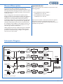
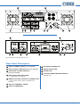
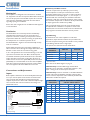
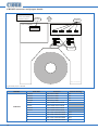
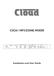
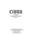
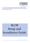
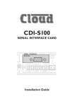
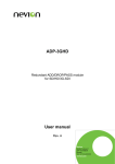
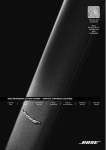
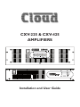
CXV-225 & CXV-425
AMPLIFIERS
Installation and User Guide
Contents
Safety Information......................................... 4
Safety Notes Regarding Installation........................ 4
Conformities................................................................ 4
Safety Considerations and Information................. 4
General Description....................................... 5
Applicable Models....................................................... 5
Schematic Diagram....................................... 5
Front Panel Description................................ 6
Rear Panel Description.................................. 7
Installation...................................................... 8
Mechanical.................................................................... 8
Ventilation..................................................................... 8
Connections and Adjustments................................. 8
Inputs............................................................................. 8
Sensitivity and Gain Control................................. 8
Input Routing............................................................ 8
Remote Control of Level....................................... 9
Outputs......................................................................... 9
Protection...............................................................10
High Pass Filters.....................................................10
VCA Cards (optional)..............................................10
Installation .............................................................10
BOSE® Equalisation Modules (Optional)............11
Installation...............................................................11
General Notes.............................................. 11
EMC Considerations................................................11
Earthing.......................................................................11
Technical Specifications............................... 12
General Specifications................................. 12
Location of Internal Jumpers and
Connectors.................................................... 13
CXV-225 connector and jumper details..............13
CXV-425 connector and jumper details..............14
CXV-225 & CXV-425 User Manual v1.0
3
Safety Information
Safety Considerations and Information
Safety Notes Regarding Installation
The unit must be earthed. Ensure that the mains power
supply provides an effective earth connection using a threewire termination.
•• Do not expose the unit to water or moisture.
•• Do not expose the unit to naked flames.
•• Do not block or restrict any air vent.
•• Do not operate the unit in ambient temperatures above
35 °C.
•• Do not touch any part or terminal carrying the
hazardous live symbol (
the unit.
) while power is supplied to
•• Do not perform any internal adjustments unless you
are qualified to do so and fully understand the hazards
associated with mains-operated equipment.
•• The unit has no user-serviceable parts. Refer servicing
to qualified service personnel.
•• If the moulded plug is cut off the AC power lead for
any reason, the discarded plug is a potential hazard and
should be disposed of in a responsible manner.
Conformities
This product conforms to the following European EMC
Standards:
BS EN 55103-1:1997
BS EN 55103-2:1997
This product has been tested for use in commercial and
light industrial environments. If the unit is used in controlled
EMC environments, the urban outdoors, heavy industrial
environments or close to railways, transmitters, overhead
power lines, etc., the performance of the unit may be
degraded.
The product conforms to the following European electrical
safety standard:
BS EN 60065:2002
The CXV Series was developed and manufactured with high
quality materials and components, which can be recycled
and/or reused.
4
CXV-225 & CXV-425 User Manual v1.0
When the mains switch is in the off ‘O’ position the live
and neutral conductors of the mains transformer are
disconnected.
Caution - High Voltages
Do not touch any part or terminal carrying the hazardous
live symbol (
) while power is supplied to the unit.
Terminals to which the hazardous live symbol refers require
installation by a qualified person.
Caution - Mains Fuse
Replace the mains fuse only with the same type and rating as
marked on the rear panel.
The fuse body size is 20 mm x 5 mm.
Caution - Servicing
The unit contains no user-serviceable parts. Refer servicing
to qualified service personnel. Do not perform servicing
unless you are qualified to do so.
Disconnect the power cable from the unit before removing
the top panel and do not make any internal adjustments with
the unit switched on.
Only reassemble the unit using bolts/screws identical to the
original parts.
General Description
Applicable Models
The Cloud CXV-225 and CXV-425 are high power (250 W/ch), multi-channel audio amplifiers intended for use
with high quality PA and background music systems in offices,
hotels, factories, leisure facilities and other commercial and
industrial premises.
They are designed to drive 100 V line speaker systems
directly, and have no low-impedance outputs. Low impedance
loudspeakers can only be connected to these amplifiers
with the use of an intermediate 100 V line transformer.
Loudspeakers designed for such ‘installed-sound’ applications
will normally include an integral transformer, typically with
selectable output power taps. If you have any doubt about
the suitability of this amplifier for the speaker system it is to
be connected to, please verify that the speakers are of the
100 V line type with the manufacturer.
This manual describes the installation and operation of the
following models:
•• Cloud CXV-225 2-channel amplifier – 2 x 250 W, 2U 19” rack unit
•• Cloud CXV-425 4-channel amplifier – 4 x 250 W, 3U 19” rack unit
Apart from the number of channels and the units’ physical
dimensions and power consumption figures, the two
models are otherwise identical for the practical purposes of
installation and operation.
Unlike traditional 100 V line amplifier designs, the CXV-225
and CXV-425 do not employ an output transformer. This
produces a considerable saving in weight and a significant
improvement in audio quality.
Schematic Diagram
CXV-225
FREQ
3
2
1
+
-
SPEAKER
EQ
VCA
+
-
CLIP
LIMITER
POWER
AMPLIFIER
OUTPUTS
1
2
3
4
5
6
7
8
PROTECT
CLIP
LIMITER
POWER
AMPLIFIER
LEVEL
+
-
PROTECT
J3
SPEAKER
EQ
VCA
FREQ
3
2
1
POWER
AMPLIFIER
LEVEL
+
-
CLIP
LIMITER
J2
SPEAKER
EQ
VCA
FREQ
3
2
1
PROTECT
LEVEL
FREQ
3
2
1
J1
VCA
J4
SPEAKER
EQ
PROTECT
CLIP
LIMITER
CHANNEL.
POWER
AMPLIFIER
LEVEL
CXV-425
fig.1: CXV Series schematic diagram
CXV-225 & CXV-425 User Manual v1.0
5
3
4
6
fig.2: CXV-425 Front panel
1
2
4
5
6
3
fig.3: CXV-225 Front panel
2
Front Panel Description
1
6
SIGNAL LEDs (one per channel) – illuminate
when the output voltage exceeds approx. 12.5 Vrms
(18 dB below maximum output)
2
PEAK LEDs (one per channel) – illuminate if
maximum output voltage is reached (100 Vrms)
3
PROTECT LEDs (one per channel) – indicate
fault conditions
CXV-225 & CXV-425 User Manual v1.0
4
AC Power switch
5
POWER LED
6
Air intake grilles
5
1
5
6
2
11
1
3
4
9
8
10
11
fig.4: CXV-425 Rear panel showing output terminal cover
5
2
9
1
4
3
7
10
8
fig.5: CXV-225 Rear panel showing output terminals
Rear Panel Description
1
Input connectors (one per channel)
8
AC mains connector
2
Input level controls (one per channel)
9
Earth safety tag
3
High Pass Filter controls (one per channel)
10
Mains fuse
4
Input routing switches – 1 for CXV-225, 3 for CXV-425
11
Cooling fans and air exhaust – CXV-425 only
5
Remote volume control connectors
– when remote control option is fitted (one per
channel)
6
Output terminal Cover
7
Output terminals
CXV-225 & CXV-425 User Manual v1.0
7
Installation
Mechanical
The amplifiers are designed to be mounted in a standard
19” equipment rack. The front panel is fitted with rackmount
ears for this purpose. The CXV-225 requires 2U of vertical
rack space, the CXV-425 requires 3U. See notes below
regarding spacing and ventilation.
Due to the units’ weight, the use of additional side supports
is recommended.
Ventilation
The CXV-425 is force cooled by two thermostaticallycontrolled fans mounted on the rear panel. The fan is
operative at all times, remaining at low speed at internal
temperatures below 50 °C, then increasing in speed above
this temperature to a maximum speed at 70 °C.
The CXV-225 has a single fan mounted internally to keep
noise to a minimum.
Always allow adequate space around the amplifier(s) to
allow a free flow of air through the unit(s). Ensure that cable
bundles or other items do not obstruct any grilles.
In 19” rack applications we recommend leaving 1U of rack
space above and below each unit. Plain 1U blank panels,
not slotted ventilation panels should be used, as the latter
reduce the effect of forced-air cooling. The direction of
airflow is from front-to-rear (CXV-425) and front-to-sides
(CXV-225); it is recommended not to mix these amplifiers
with other equipment employing forced-air cooling which
acts in the opposite direction within the same rack.
Connections and Adjustments
Inputs
Each amplifier channel has an electronically-balanced input
on a 3-pin 3.5 mm-pitch screw terminal connector. Twincore screened cable should be used when driving the
amplifier inputs from a device with a balanced output. Singlecore screened cable can be used when connecting to an
unbalanced source.
1
2
3
-
-
+
3
+
1
2
BALANCED CONNECTION
Balanced output
(typically XLR):
pin 1: ground
pin 2: hot
pin 3: cold
Amplifier input
pin 1: n/c
pin 2: cold
pin 3: hot
1
2
-
Unbalanced outputs
(e.g. phonos):
screen: ground
pin:
hot
UNBALANCED CONNECTION
fig.6: Input wiring
8
CXV-225 & CXV-425 User Manual v1.0
3
+
Amplifier input
pin 1: n/c
pin 2: cold
pin 3: hot
Sensitivity and Gain Control
Control of input level is provided by a preset rotary
control adjacent to each input connector. The control
should be adjusted using a trim tool or small screwdriver.
Full attenuation of the input signal – i.e., zero output – is
obtained with the control fully anti-clockwise. Maximum
sensitivity is with the control fully clockwise; at this setting
the maximum output level of 100 Vrms will be produced for
an input signal level of 0.775 Vrms (0 dBu).
We recommend that the level for each channel should
be adjusted after installation is complete to ensure that
adequate, but not excessive sound levels are achieved with
the programme material that will be used in practice.
Input Routing
To facilitate the use of the amplifiers in multi-zone
applications, input selection switches are provided on all
channels except Ch1. This gives the installer an easy method
of paralleling channels from a single input.
The options are summarised in the table below:
CHANNEL
SOURCE
Button position
Channel 2
Channel 3
Channel 4
CXV-225
Out
Input 1
CXV-425
In
Input 2
Out
Input 1
Input 1
Input 2*
In
Input 2
Input 3
Input 4
* post Ch 2 switch
Refer also to the block diagram on page 5.
CXV-225 only: The CXV-225’s single switch allows
Channel 2 to be operated in parallel with Channel 1, with
Input 1 acting as the common input connector.
CXV-425 only: The three switches on the CXV-425 allow
a total of 8 routing possibilities, including 4-channel, dual
stereo and mono operation with 4 channels paralleled. The
table below clarifies the options:
BUTTON
POSITION
INPUT ROUTING: CHANNELS
FED BY EACH INPUT
Ch 1
Ch 2
Ch 3
Input 1
Input 2
Input 3 Input 4
In
In
In
Ch 1
Ch 2
Ch 3
Ch 4
Out
In
In
Chs 1 & 2
Ch 3
Ch 4
In
Out
In
Chs 1 & 3
Out
Out
In
Chs 1, 2 & 3
In
In
Out
Ch 1
Out
In
Out
Chs 1, 2 & 4
In
Out
Out
Chs 1 & 3
Out
Out
Out
Chs 1, 2, 3 & 4
Ch 2
Ch 4
Ch 4
Chs 2 & 4
Ch 3
Ch 3
Chs 2 & 4
Remote Control of Level
The CXV-225 and CXV-425 amplifiers are compatible with
standard Cloud remote control plates type RL-1, allowing
control of level from a remote position. In order to use
the amplifiers with the RL-1,VCA cards must first be fitted
in the channels to be controlled remotely. See page 10 for
details of VCA cards and fitting. Once VCA cards have been
fitted, RL-1s may be connected at the rear 3-pin 5 mm-pitch
screw terminal connectors (Remote Level), using the wiring
shown below.
RL-1
REMOTE LEVEL
CONNECTOR
1
2
3
1
2
Outputs
The 100 V line speaker output terminals are behind the
removable output terminal cover (see page 7). The covers
are fitted with a cable gland (one per channel); to use these,
slacken the rear nut by a few turns and feed the cable
through. The plug-in connectors are suitable for cable cores
up to 2.5 mm2.
Connect as shown below:
CXV-425
3
1
2
-
3
+
4
-
CH 1
5
+
CH 2
6
-
7
+
CH 3
8
-
+
CH 4
USE TWO-CORE SCREENED CABLE
fig.7: Remote level control wiring
CXV-225
Use two-core screened cable to connect the remote level
plate (maximum length 100 metres).
1
2
-
3
+
CH 1
4
-
+
CH 2
fig.8: Output wiring
After making the connections, replace the cover and tighten
the gland nuts. They only need to be firmly finger-tight; take
care not to over tighten, use only enough torque to give
reasonable cable retention. Do not use a spanner.
Caution: The amplifier should never be operated without
the output terminal cover installed. Apart from exposing
the high voltage terminals, leaving the cover off also
compromises the amplifier’s forced-air cooling.
The amplifier’s transformerless output stage is designed
to drive up to 100 Vrms into an impedance of at least 40 ohms (each channel). Check the input impedance of the
loudspeaker type in use and divide this figure by the number
of loudspeakers* to ensure that the total impedance is
greater than 40 ohms. Alternatively, add the wattages of all
the loudspeakers being driven by each channel (taking power
tappings into account); the total must be less than 250 W.
* Assumes all loudspeakers in the system are of the same type and have the
same tap setting.
CXV-225 & CXV-425 User Manual v1.0
9
Protection
The amplifiers include comprehensive protection circuitry
to prevent damage to loudspeakers, the output devices and
other components in the event of a fault condition.
Thermal Protection
The output device heatsink temperatures are monitored and
the protection circuitry activated if any should exceed 90°C.
The red front panel PROTECT LED for the appropriate
channel illuminates to indicate the fault condition.
DC Protection
Crowbar protection is provided to safeguard the
loudspeakers in the event of DC being present at the output
terminals. This is an emergency protection feature that
will only operate in the event of the amplifier developing a
fault. Its action is liable to blow internal DC rail fuses. The
amplifier must be serviced before any attempt is made to
use it further.
voices contain any useful signal below 200 Hz, so in many
cases the filter can be set to 200 Hz without any real loss
of quality. Often a setting this high will actually enhance the
clarity of the speech, reduce microphone handling noise and
reduce breath blasts.
For music systems
The optimum filter setting will depend on the speakers and
their transformers. It should be recognised that many 100 V line speakers have inferior LF performance
compared to low impedance speakers. If the manufacturer
recommends a minimum frequency of operation, set the
filter to this. Otherwise, settings between 70 Hz and 100 Hz
should be appropriate.
Test the system at full volume with a variety of music
containing high level, low bass notes and listen for any
distortion. If the transformers saturate, distortion will be
clearly audible. In this case, turn the control clockwise until
it disappears.
Short-circuit protection
VI limiting is implemented in the amplifiers to protect the
output stages from excessive dissipation caused by abnormal
loads; for example, a short-circuit.
Switch-on protection
The protection circuitry is also activated immediately after
the amplifier is switched on. This is to prevent any voltage
spikes due to start-up conditions from damaging the
loudspeakers. The protection circuitry automatically times
out after approx. 5 seconds. All PROTECT LEDs illuminate at
switch-on for the duration of the time-out period.
High Pass Filters
Most transformers fitted to 100 V line speakers exhibit
core saturation when fed with high-level signals at low
frequencies. Transformer saturation creates unpleasant
distortion and stresses the system. To counteract this, a
correctly configured high pass filter is an essential part of
any 100 V line system. The CXV-225 and CXV-425 have
variable frequency high pass filters in each channel, accessible
at the rear panel (see page 7). These should be adjusted to
reject low frequencies, to suit both the speakers and the
application. When adjusting, bear in mind that the higher
the frequency setting, the less likely it is that the system will
suffer from saturation problems.
The minimum (20 Hz) setting should only be used when
the system has some other form of filter or protection
from high-level low frequency signals (e.g., a dedicated
speaker processor) or when the speaker manufacturer
explicitly states that they will operate correctly at such low
frequencies.
For speech-only
Settings somewhere between 100 Hz (12 o’clock) and 200
Hz are appropriate. Start with the filter set to 100 Hz and
turn the control clockwise whilst listening to speech through
the system until you can hear a loss of bass in the voice. Few
10
CXV-225 & CXV-425 User Manual v1.0
VCA Cards (optional)
Cloud VCA-5 modules must be fitted to the CXV-225
and CXV-425 amplifiers if remote control of audio level is
required. One VCA-5 module is required for each channel,
and as many as necessary may be fitted. The VCA modules
use the industry-standard That’s 2181 VCA device, which
provides very low distortion and up to 90 dB attenuation at
cut-off.
The VCA module can also be used to provide muting by
using an auxiliary relay connected to a fire alarm control
panel. Please contact our technical department for further
details.
Installation
•• With the power turned off and the mains cable
removed, remove the top panel.
•• Refer to the pcb layout diagrams on page 13. Locate the
VCA connector for the first channel being fitted, and
remove the jumper joining one pair of pins.
•• Unscrew the blanking plate from the rear panel.
•• Remove and retain the M3 fixing screw adjacent to the
connector, and fit the 35mm M3 hex spacer supplied
with the VCA-5 in its place.
•• Push the 10-way VCA plug onto the PCB connector,
aligned so the cable enters it from the rear of the
chassis. Check there is contact with all 10 pins.
•• Locate the VCA module’s 3-pin socket in the rear panel
cut-out and secure using the M3 screw provided.
•• Replace the top panel.
Once the VCA-5 modules have been installed, RL-1 remote
level control plate(s) may be connected to the REMOTE
LEVEL connector(s) on the rear panel.
BOSE® Equalisation Modules (Optional)
The CXV-225 and CXV-425 are compatible with Bose®
Series II loudspeakers; a single-channel Bose® equalisation
module may be fitted to as many channels as necessary.
Equalisation modules for the following Bose® models are
available:
•• Panaray® MA12
•• Panaray® 402-II, 502B and 502BEX
•• Panaray® LT Series: Models 3302, 4402, 9402 and 9702
•• Freespace® DS 16 range
•• Freespace® Model 16
•• Freespace® Model 32 range
Other modules are available; please enquire.
Installation
•• With the power turned off and the mains cable
removed, remove the top panel.
•• Refer to the pcb layout diagrams on page 13. The
modules plug into the white 12-pin connectors on the
PCB. Note the header connectors on the PCB have two
notches on one side only; these engage with lugs on
the equalisation module’s mating connector to ensure
correct orientation.
•• After fitting equalisation modules to any channel(s),
the corresponding module bypass jumper(s) must be
removed in order for the module to function. Refer to
the pcb layout diagrams for jumper locations.
•• Replace the top cover with the original screws after
fitting
General Notes
EMC Considerations
CXV Series amplifiers fully conform to the relevant
electromagnetic compatibility (EMC) standards and are
technically well behaved.You should experience no problems
interfacing units to other items of equipment and under
normal circumstances, no special precautions need to
be taken. If the unit is to be used in close proximity to
potential sources of HF disturbance such as high power
communication transmitters, radar stations and the like, it is
suggested that input signal leads be kept as short as possible.
Always use balanced interconnections wherever possible.
Earthing
When several mains powered units are connected together
via their signal cables, there is a risk of one or more earth
loops which may cause an audible hum on the system even
with the gain controls set to minimum.
The 0 V rail of a CXV Series amplifier is directly coupled to
the chassis ground. No interconnection problems should be
encountered, but if there is any hum or other extraneous
noise when source equipment is connected, the situation can
generally be remedied by observing the following guidelines:
•• Always connect sources using balanced connections
wherever possible, with the cable screen only connected
at the receiving end (amplifier input).
•• Use audio isolating transformers (readily available from
trade suppliers) at the inputs if necessary. These will
ensure that the amplifier is electrically isolated from the
source equipment.
•• The signal source units should be located as close as
possible to the amplifiers and the metal housing of
the various units should not be electrically connected
together through the equipment rack. If this is a
problem, rack isolating kits are available from specialist
hardware suppliers. If the problem persists, try to
connect all interconnected units, including power
amplifiers, to a common power source to ensure a
common ground is provided.
CXV-225 & CXV-425 User Manual v1.0
11
Technical Specifications
Outputs
Frequency Response
High Pass Filter
Distortion
Crosstalk
Sensitivity
Input Impedance
Noise (rms)
Power Input
Fuse Rating
Fuse Type
CXV-225 & CXV-425
100 Vrms; 250 W into 40 Ω min. load (per channel)
20 kHz -0.6 dB; LF response dependent on filter setting
-3 dB @ 20 Hz – 200 Hz variable
<0.04% @ 1 kHz & 1 dB below limiting, 40 Ω load
-80 dB @ 10 kHz
0.775 Vrms (0 dBu)
10 kΩ balanced, 5 kΩ unbalanced
-96 dB, 22Hz - 22kHz, relative to 100 Vrms
230 V ±5%
230 V, 5 A
T5A, 20 mm x 5 mm 250V
General Specifications
Inputs
Outputs
Protection
Status Indicators
Cooling
Dimensions
(mm, W x H x D)
Weight
12
CXV-225
CXV-425
Electronically balanced; 3-pin 2.5 mm-pitch plug-in screw terminal connectors
2-pin 5 mm-pitch plug-in screw terminal connectors
Clip Limiting,VI Limiting, DC Offset, Thermal & switch-on delay
LED indicators on each channel for Signal, Peak & Protect
Force cooled; internal variable speed
Force cooled; two rear-mounted
DC fan
variable speed DC fans
482.6 x 88 (2U) x 300 (+ connectors)
482.6 x 132.5 (3U) x 332
(+ connectors)
8.8 kg net
21 kg net
CXV-225 & CXV-425 User Manual v1.0
Location of Internal Jumpers and Connectors.
CXV-225 connector and jumper details
REAR OF AMPLIFIER
CXV-225: MAIN PCB LAYOUT.
VCA CARD
SOCKETS
TOP VIEW. ONLY PRIMARY
COMPONENTS SHOWN.
OUTPUT
TERMINALS
CON3
CON1
BOSE EQ® CARD
BYPASS JUMPERS
FAN ASSY.
CON9
CON10
J2
J1
BOSE ® EQ CARD
SOCKETS
fig.9: Internal jumpers - CXV-225
NOT TO SCALE
MODEL
CXV-225
PCB REF
CON1
CON3
Function
CH1 VCA CARD
CH2 VCA CARD
CON9
CH1 BOSE® EQ CARD
CON10
CH2 BOSE® EQ CARD
CH 1 EQ CARD BYPASS
CH 2 EQ CARD BYASS
J1
J2
Default Setting
SET
SET
SET
SET
CXV-225 & CXV-425 User Manual v1.0
13
CXV-425 connector and jumper details
REAR OF AMPLIFIER
CXV-425: MAIN PCB LAYOUT.
TOP VIEW. ONLY PRIMARY
COMPONENTS SHOWN.
OUTPUT
TERMINALS
VCA CARD
SOCKETS
(INPUTS 3 & 4 SUB BOARD)
(OUTPUT SUB BOARD)
CON25
CON24
CON13
CON15
J2
CON12
CON5
J1
CON17
J4
BOSE EQ® CARD
BYPASS JUMPERS
CON6
J3
BOSE ® EQ CARD
SOCKETS
NOT TO SCALE
fig.10: Internal jumpers - CXV-425
MODEL
PCB REF
CON12
CON13
CON24
CON25
CON5
CXV-425
14
Function
CH1 VCA CARD
CH2 VCA CARD
CH3 VCA CARD
CH4 VCA CARD
Default Setting
SET
SET
SET
SET
CH1 BOSE® EQ CARD
CON6
CH2 BOSE® EQ CARD
CON15
CH3 BOSE® EQ CARD
CON17
CH4 BOSE® EQ CARD
J1
CH 1 EQ CARD BYPASS
SET
J2
CH 2 EQ CARD BYPASS
SET
J3
CH 3 EQ CARD BYPASS
SET
J4
CH 4 EQ CARD BYPASS
SET
CXV-225 & CXV-425 User Manual v1.0
Bose® is a registered trademark of The Bose Corporation.
In the interest of continuing improvements Cloud Electronics Limited reserves
the right to alter specifications without prior notice.
CXV-225 & CXV-425 User Manual v1.0
15
Cloud Electronics Limited
140 Staniforth Road
Sheffield S9 3HF
England
Tel: +44 (0)114 244 7051
Fax: +44 (0)114 242 5462
email: [email protected]
web: www.cloud.co.uk