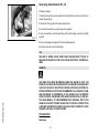
1
PIAGGIO WOULD LIKE TO THANK YOU
for choosing one of its products. We have prepared this booklet to help you to get the very best from your scooter. Please read it carefully before riding
the scooter for the first time. It contains information, tips and precautions for using your scooter. It also describes features, details and devices to assure
you that you have made the right choice. We believe that if you follow our suggestions, you will soon get to know your new vehicle and it will serve you
well for a long time to come. This booklet forms an integral part of the scooter; should the scooter be sold, it must be transferred to the new owner.
X9 Evolution 500
The instructions given in this manual are intended to provide a clear, simple guide to using your scooter; this booklet also details routine maintenance
procedures and regular checks that should be carried out on the vehicle at an authorised Dealer or Service Centre. The booklet also contains
instructions for simple repairs. Any operations not specifically described in this manual require the use of special tools and/or particular technical
knowledge: to carry out these operations refer to any authorised Dealer of Service Centres.
2
Personal safety
Failure to completely observe these instructions will result in serious risk of personal
injury.
Safeguarding the environment
Sections marked with this symbol indicate the correct use of the vehicle to prevent damaging the environment.
Vehicle intactness
The incomplete or non-observance of these regulations leads to the risk of serious
damage to the vehicle and sometimes even the invalidity of the guarantee.
The signs that you see on this page are very important. They are used to highlight those
parts of the booklet that should be read with particular care. As you can see, each sign
consists of a different graphic symbol, making it quick and easy to locate the various
topics.
3
4
INDEX
VEHICLE......................................................................................
Dashboard................................................................................
Analogue instrument panel.......................................................
Instruments...............................................................................
Digital lcd display......................................................................
Maintenance icons................................................................
Setting the total and trip odometers......................................
Setting the outside temperature display................................
Kilometres/miles covered in reserve symbol.........................
Clock/date display.................................................................
Setting the hour/minutes function..........................................
Setting the date function........................................................
Setting the chronometer function..........................................
Key switch.................................................................................
Locking the steering wheel....................................................
Releasing the steering wheel................................................
Switch direction indicators........................................................
Horn button...............................................................................
Light switch...............................................................................
Emergency flashing light button................................................
Start-up button..........................................................................
Engine stop button....................................................................
Electric kickstand operation button...........................................
The immobilizer system............................................................
Keys......................................................................................
Immobilizerdevice enabled indicator led...............................
Operation...............................................................................
Programming the immobilizer system...................................
Saddle opening remote control.................................................
Accessing the fuel tank.............................................................
Power supply socket.................................................................
The saddle................................................................................
7
8
9
9
10
11
11
12
12
13
13
14
14
15
15
15
16
16
17
17
18
18
19
19
19
20
21
21
23
23
24
25
Opening the saddle to access the helmet compartment by
remote control....................................................................... 26
Opening the saddle............................................................... 27
Opening the saddle to access the helmet compartment in an
emergency............................................................................. 27
Identification.............................................................................. 28
Adjusting the windscreen.......................................................... 28
USE.............................................................................................. 31
Checks...................................................................................... 32
Refuelling.................................................................................. 32
Tyre pressure............................................................................ 34
Shock absorbers adjustment.................................................... 36
Anti-overturning sensor............................................................. 37
Running in................................................................................. 37
Starting up the engine............................................................... 38
Precautions........................................................................... 39
Difficult start up......................................................................... 40
Stopping the engine.................................................................. 41
Stand......................................................................................... 41
Electro-hydraulic stand............................................................. 42
Activation conditions.............................................................. 42
Automatic transmission............................................................. 44
Safe driving............................................................................... 44
Introduction............................................................................ 46
Legend.................................................................................. 47
Installing the microphone/earphone...................................... 49
Use and general functions..................................................... 50
Intercom operation................................................................ 51
Speakerphone kit for mobile phone operation....................... 52
Radio/rds function................................................................. 53
Special functions................................................................... 55
Icon description..................................................................... 0
MAINTENANCE........................................................................... 61
5
Engine oil level.......................................................................... 62
Engine oil level check............................................................ 62
Engine oil top-up................................................................... 63
Warning light (insufficient oil pressure)................................. 63
Engine oil change.................................................................. 64
Hub oil level.............................................................................. 65
Tyres......................................................................................... 68
Spark plug dismantlement........................................................ 70
Removing the sides.................................................................. 71
Removing the air filter............................................................... 73
Cooling fluid level...................................................................... 73
Checking the brake oil level...................................................... 75
Braking system fluid top up................................................... 76
Battery....................................................................................... 78
Use of a new battery............................................................. 79
Checking the electrolyte level................................................ 79
Long periods of inactivity.......................................................... 80
Fuses........................................................................................ 81
Front light group........................................................................ 86
Headlight adjustment............................................................. 87
Front direction indicators........................................................... 88
Rear optical unit........................................................................ 89
Number plate light..................................................................... 90
Helmet compartment lighting bulb............................................ 90
Brake light................................................................................. 90
Rear-view mirrors...................................................................... 91
Front and rear disc brake.......................................................... 91
Puncture.................................................................................... 93
Periods of inactivity................................................................... 94
Cleaning the vehicle.................................................................. 94
TECHNICAL DATA...................................................................... 99
Kit equipment............................................................................ 105
SPARE PARTS AND ACCESSORIES........................................ 107
Warnings................................................................................... 108
PROGRAMMED MAINTENANCE............................................... 111
Scheduled maintenance table................................................... 112
6
X9 Evolution
500
Chap. 01
Vehicle
7
Dashboard (01_01, 01_02, 01_03)
A = Key switch
B = Start-up button
C = Accelerator control
D = Front brake control
E = Saddle electric opening button
01_01
F = Digital instrument panel
G = Direction indicator switch
H = Light switch
I = Combined braking control (front and rear)
L = Horn button
M = Engine lock RUN-OFF switch
N = Emergency flashing light start button (4 direction indicators)
O = Indicator unir
01_02
P = Electro-hydraulic stand button
R = Analogue instrument unit
S = PICS (Piaggio Integrated Communication System)
1 Vehicle
T = Bag clip
01_03
8
A = Double scale speedometer (km/h and mph)
B = Fuel level indicator
C = Rpm counter
D = Cooling fluid temperature indicator
U = Alarm led
01_04
Instruments (01_05)
A = RH direction indicator
B = LH direction indicator
C = Emergency flashing light indicator (4 direction indicators)
D = RUN-OFF light stop engine/side stand lowered
E = Fuel reverse indicator
01_05
F = Light indicator
G = Upper beam indicator
H = Low oil pressure indicator
I = Engine run light and injection fault indication*
L = Electro-hydraulic stand alarm light
M = ABS light (setup)
N = LCD display
O = «Mode» button
9
1 Vehicle
Analogue instrument panel (01_04)
P = «Trip» button
Q = «Clock» button
R = "Set" button
* See section "Engine stop button"
Digital lcd display (01_06)
1 = Maintenance icon «OIL»;
2 = Maintenance icon «SERVICE»;
3 = Maintenance icon «BELT»;
4 = Trip odometer display symbols «T1» or «T2»;
5 = Five-digit display for kilometres/miles covered;
01_06
6 = Display mode symbols «Km» or «Mi»;
7 = Kilometres/miles covered in reserve symbol;
8 = 2-digit display with symbols «-» temperature display, mean speed, maximum
speed; kilometres/mph covered in reserve;
9 = Mean speed mode display symbol «MEAN»;
10 = Maximum speed mode display symbol «MAX»;
11 = 4-digit display of clock, chronometer and date functions;
1 Vehicle
12 = Time indication symbols «AM» or «PM»
10
The icons warn the user when the scheduled maintenance interventions are required.
If the «OIL» icon flashes, the engine oil needs to be changed.
If the «SERVICE» icon flashes, scheduled servicing indicated on the coupons needs
to be effected.
If the «BELT» icon flashes, the distribution belt needs to be changed.
WARNING
01_07
REFER TO THE «SCHEDULED MAINTENANCE TABLE» FOR FURTHER MAINTENANCE OPERATIONS
Setting the total and trip odometers (01_08)
The «TRIP» button displays partial distances «T1» and «T2» and the total distance,
if pressed repeatedly for less than 1 second.
Press it for over 3 seconds to reset the trip odometer. Press «TRIP» again to return
to the total odometer «5».
01_08
11
1 Vehicle
Maintenance icons (01_07)
Setting the outside temperature display (01_09)
The temperature value «8» updates automatically at every variation of ± 1 °C. When
the external temperature reaches +3 °C, the display flashes for 40 seconds; the same
occurs at every decrease of temperature.
01_09
Press «M» to display the mean speed, identified by symbol «MEAN», which updates
automatically every 30 seconds even if the key is set to «OFF». Press «M» to display
the maximum speed reached by the vehicle and identified by the symbol «MAX»,
press again to display the kilometres traveled in reserve; the value is stored also with
key set to «OFF». Press «M» again to return to the outside temperature display. Keep
«M» pressed for more than 3 seconds to reset the selected function, except the temperature.
WARNING
WARNING
THE FLASHING FUNCTION WHEN A TEMPERATURE OF +3 °C AND LESS IS
REACHED HAS PRIORITY ON THE MEAN AND MAX SPEED INDICATION, SO IT
IS AUTOMATICALLY DISPLAYED. HOWEVER, YOU CAN PRESS BUTTON «M»
TO DISPLAY THE SPEED AND DISTANCE COVERED IN RESERVE VALUES.
Kilometres/miles covered in reserve symbol (01_10, 01_11)
The symbol is automatically displayed when the fuel reserve light indicator «E» turns
on, along with indicator «8» of the kilometres/mph covered in reserve. This function
has the utmost priority over the previous three ones, so when the vehicle is in reserve,
icon «7» is automatically displayed along with the kilometres being covered in reserve
are displayed. Press «M» to return to the other information.
N.B.
N.B.: THE AVERAGE MILEAGE IS CALCULATED BASED ON EACH RESET AND
IS AFFECTED BY THE VEHICLE'S ROUTE AND AMOUNT OF TIME.
1 Vehicle
01_10
12
1 Vehicle
01_11
Clock/date display (01_12)
Press «CLOCK» to display the date (day/month). Press «CLOCK» to display the
chronometer.
Press «CLOCK» to return to the clock display «12».
01_12
Setting the hour/minutes function (01_13)
Press «CLOCK» for more than 3 seconds and set the time by button «S».
Wait until the minutes begin flashing and set by button «S».
Wait approx. 8 seconds or press «CLOCK» to return to the updated hours/minutes
function.
01_13
13
Setting the date function (01_14)
Press «CLOCK» for more than 3 seconds and set the day by button «S». Wait until
the month begins flashing and set by button «S». Wait until the year begins flashing
and set by button «S». Wait approx. 3 seconds or press «CLOCK» to return to the
date function.
01_14
Setting the chronometer function (01_15)
Press «S» to enable and stop the chronometer. Press «CLOCK» and «S» together
to reset the chronometer.
WARNING
TO KEEP TRACK OF THE JOBS FOR «SERVICE», THE CLOCK MUST BE RESET
EACH TIME THE BATTERY IS DISCONNECTED FROM THE VEHICLE SYSTEM.
CAUTION
01_15
1 Vehicle
IT IS STRONGLY ADVISED NOT TO USE THE FUNCTIONS OF THE DIGITAL
DISPLAY PANEL WHILE THE VEHICLE IS MOVING.
14
LOCK= Ignition barred, key can be removed, mechanical antitheft device activated.
OFF= Ignition barred, key can be removed, mechanical antitheft device deactivated.
ON= Prestarting position, key cannot be removed, mechanical antitheft device deactivated.
01_16
Locking the steering wheel
Turn the handlebar to the left (as far as it will go), turn the key to «LOCK» and remove
the key.
CAUTION
DO NOT TURN THE KEY TO «LOCK» OR «OFF» WHILE RIDING.
Releasing the steering wheel
Reinsert the key and turn it to «OFF».
CAUTION
DO NOT TURN THE KEY TO «LOCK» OR «OFF» WHILE RIDING.
15
1 Vehicle
Key switch (01_16)
Switch direction indicators (01_17)
Lever to «S» = left direction indicators on;
Lever to «D» = right direction indicators on;
The lever automatically returns to position «0» and the indicators «B» remain on; press
the lever to turn them off.
WARNING
WARNING
01_17
THE ONBOARD COMPUTER DISABLES THE FLASHING LIGHTS AFTER 1 KM.
Horn button (01_18)
Push the «C» button to sound the horn.
1 Vehicle
01_18
16
0 = Low-beam light
1 = High beam light
2 = Passing (flashing)
01_19
Emergency flashing light button (01_20)
It starts the 4 direction indicators at the same time. The control «H» can only be enabled with key set to «ON», but once it has been enabled it remains on with key set
to «OFF» and «LOCK» as well.
This function can only be disabled with key switch set to «ON».
01_20
17
1 Vehicle
Light switch (01_19)
Start-up button (01_21)
Starter button "G"
01_21
Engine stop button (01_22, 01_23)
0 = OFF
1 = RUN
Use of the emergency stop switch causes the lights «I» and «D» to go on.
The «I» light which indicates the check of the injection system which, other than going
on temporarily after switching from «OFF» to «RUN» of the emergency stop switch,
goes on also in the following conditions:
01_22
- Moving the key switch from «OFF» to «ON»;
- Side stand from lowered to raised position;
- Emergency stop switch from «OFF» to «RUN»;
1 Vehicle
If the light remains on or goes on while normally using the vehicle, contact an Authorized Piaggio Service Center to solve the problem.
01_23
18
Electro-hydraulic stand button.
01_24
The immobilizer system
In order to enhance theft protection, the scooter is equipped with a «PIAGGIO IMMOBILIZER » electronic engine locking device that is activated automatically when
the starter key is removed. Upon start-up, the «PIAGGIO IMMOBILIZER» system
checks the starter key, and only if this key is recognised will the immobilizer system
allow the scooter to be started.
Keys (01_25, 01_26, 01_27)
Two types of keys come with the vehicle. The red-handgrip key "A" is the "MASTER" key. Only a single copy of this key is supplied, which is necessary to program
all your other keys and for your dealer to perform some maintenance operations. For
this reason it is advised that it be used only in exceptional circumstances. The black
key "B" (single copy supplied) is used for normal operations such as:
- engine start up
- glove-box opening
01_25
Together with the keys comes a CODE CARD which is imprinted with the mechanical
code of the keys.
19
1 Vehicle
Electric kickstand operation button (01_24)
WARNING
LOSING THE RED KEY PREVENTS ANY REPAIRS OF THE 'PIAGGIO IMMOBILIZER' SYSTEM AND THE ENGINE CONTROL UNIT.
WARNING
01_26
KEEP THE 'CODE CARD' AND THE RED HANDGRIP KEY IN A SAFE PLACE (NOT
ON YOUR VEHICLE).
01_27
Immobilizerdevice enabled indicator led (01_28)
The enabling of the «PIAGGIO IMMOBILIZER» system is indicated by the flashing of
a special led «U», (see «Analogue instrument panel»).
To prevent discharging the battery, the led automatically turns off after about 48 hours
of continuous operation.
1 Vehicle
In the event of system failure, the indicator led informs the Authorised Piaggio Service Centre of the nature of the failure, based on the type of flashes emitted.
01_28
20
Every time the starter key is removed in the "OFF" or "LOCK" position, the safety
system activates the immobilizer system. Turning the key to "ON" disables the engine
lock, provided that the safety system recognises the code transmitted by the key. If
the code is not recognised, turn the key first to "OFF" and then to "ON"; if the lock
cannot be disabled, try with the other key supplied (red-coloured). If the engine cannot
be started, contact an authorised Piaggio service centre, which is provided with the
electronic equipment required to detect and repair the system. The immobiliser is activated even when the engine is switched off with the engine cut-off switch. This
happens even if the starter key is in position "ON". When additional keys are required,
please note that data storage (up to 7 keys max.) must be done on all keys, both new
ones and existing ones. Take the key with the red grip and all the black keys supplied
to an authorised Piaggio service centre. The codes of keys not submitted for the
new storage procedure are deleted from the memory. Any lost keys will therefore not
be enabled to start the engine.
WARNING
EACH KEY HAS ITS OWN AND UNIQUE CODE, WHICH MUST BE STORED BY
THE SYSTEM CONTROL UNIT.
VIOLENT SHOCKS MAY AFFECT THE ELECTRONIC COMPONENTS OF THE
KEY.
IF OWNERSHIP OF THE VEHICLE IS TRANSFERRED, THE RED-HANDGRIP KEY
(AS WELL AS THE OTHER KEYS) AND THE "CODE CARD" MUST ALSO BE
TRANSFERRED TO THE NEW OWNER.
Programming the immobilizer system
The procedure for programming the «PIAGGIO IMMOBILIZER» system and/or for
storing other key codes is described below.
21
1 Vehicle
Operation
Procedure start - red key
Insert the red-handgrip key in the switch key (in "OFF" position) and turn it to "ON".
After 1 - 3 seconds, turn the key to "OFF" again and pull it out.
Intermediate step - black key
After pulling out the red key, insert the black key within 10 seconds and promptly turn
it to "ON". After 1-3 seconds, turn the key to "OFF" again and pull it out. In this way,
a maximum of 3 black keys can be programmed by repeating the above procedure
keeping the indicated times.
Final step - red key
After pulling out the last black key, insert the red key again and turn it to "ON" (this
operation should be performed within 10 seconds of pulling out the previous key).
Leave it in this position for 1 to 3 seconds and return it to the «OFF» position.
Proper programming check
Insert the red key disabling the transponder (i.e., tilt the key cap by 90°) and turn the
key to "ON". Perform the engine start-up operation. Ensure that the engine does not
start. Insert the black key and repeat the start-up operation. Check that engine starts.
WARNING
1 Vehicle
SHOULD THE ENGINE START WITH THE RED KEY (WITH TRANSPONDER OFF),
OR IN THE EVENT OF WRONG OPERATION DURING PROGRAMMING, REPEAT
THE PROCEDURE FROM THE BEGINNING.
22
01_29
The vehicle comes with a remote control for remote opening of the saddle. The saddle
is supplied together with the keys and is matched to the opening device control unit
in the factory. It is nevertheless possible to ask for a new one and reprogram it in the
event the remote control is lost. This procedure can be performed at an Authorised
Piaggio Service Centre. The remote control is a device powered by internal batteries,
so it is subject to running down with use. If the green LED turns on when the button
is pressed, it is operating properly. Battery replacement may become necessary when
you notice the range of action is smaller or if it does not work.In this case you have to
separate the remote control's two half-shells by inserting a blade or the very fine tip
of a screwdriver in a point along the outside edge and then run it along the entire
circumference. Now extract the two batteries from the contact plate on the printed
circuit. Place the new batteries, type CR1616, with the positive pole turned towards
the contact plate. Now put the board back on the rear half-shell with the button and
LED turned outwards. Mount the pressure rubber on the button (the direction it is
inserted is obligatory) and snap on the front half-shell. To open the saddle without
using the remote control, it is possible to do so by following the directions given in
section «Opening the saddle to access the helmet compartment» or «Opening the
saddle to access the helmet compartment in an emergency».
01_30
Accessing the fuel tank (01_31, 01_32)
Insert the key into the switch and press down until the glove box opens. In the event
that the key switch is in «LOCK», turn the key to «OFF» or «ON» before pressing
down. Press lever «B» and open the cover over the fuel tank cap «C».
01_31
23
1 Vehicle
Saddle opening remote control (01_29, 01_30)
01_32
Power supply socket (01_33)
There is a plug socket "D" inside the helmet compartment.
The plug socket may be used for external consumers (mobile phone, inspection light,
etc.).
CAUTION
01_33
PROLONGED USE OF THE PLUG SOCKET MAY RESULT IN PARTIAL DISCHARGE OF THE BATTERY
Electric characteristic
Plug socket
12 V - 180 W MAX
1 Vehicle
Maximum power
180 W
24
The saddle is provided with a back that can be moved forward or backward for your
comfort. To move the back, raise the saddle by button «C», on the remote control or
push lever «A», and adjust the position of screws «B».
The saddle is provided with a protective covering that may be used, for example, in
case of rain. To use the covering, raise the saddle and pull it out. Fit it onto the saddle
without pulling too much to prevent breakage, then close the saddle.
CAUTION
01_34
DO NOT USE THE VEHICLE WITHOUT THE PROTECTION COVER.
01_35
01_36
25
1 Vehicle
The saddle (01_34, 01_35, 01_36, 01_37, 01_38)
01_37
01_38
Opening the saddle to access the helmet compartment by
remote control
With the key in «LOCK» or «OFF» position it is possible to open the saddle by remote
control. It cannot be opened with the key in the «ON» position.
1 Vehicle
WARNING
THE REMOTE CONTROL OPERATES WITHIN A DISTANCE OF ABOUT 3/5 METRES WITH FULLY CHARGED BATTERIES. WHEN YOU ARE NEAR THE
SCOOTER, HANDLE THE REMOTE CONTROL CAREFULLY SO AS TO AVOID
26
Opening the saddle (01_39)
With the key in the «OFF» or «ON» position or with the engine off, the saddle can be
opened electrically by pressing button «C». If the electrical opening does not work,
see paragraph «Opening the saddle to access the helmet compartment in an emergency». The key must be in the «LOCK» position to prevent the saddle from being
opened with button «C».
01_39
Opening the saddle to access the helmet compartment in an
emergency (01_40)
With the key in the «OFF» or «ON» position it is possible to open the front glove box
by pressing on the key switch. Then use lever «A» to open the saddle.
N.B.
PAY SPECIAL ATTENTION WHEN PLACING OBJECTS ON THE SADDLE AS THE
AUTOMATIC OPENING OF THE SADDLE CAN CAUSE THEM TO FALL.
01_40
WARNING
OBJECTS INAPPROPRIATELY PLACED INSIDE THE HELMET COMPARTMENT
MAY DEFORM THE SADDLE AND PREVENT THE COURTESY LIGHT FROM
TURNING OFF, WHICH MAY RESULT IN BATTERY DISCHARGE.
27
1 Vehicle
UNINTENTIONAL OPENING OF THE SADDLE. REFER TO THE «OPENING THE
SADDLE WITH REMOTE CONTROL» SECTION TO REPLACE BATTERIES.
Identification (01_41, 01_42)
The identification registration numbers consist of a prefix stamped on the chassis and
engine "B" respectively, followed by a number. These numbers must always be indicated on spare parts requests. To read the chassis number, remove the relevant port
"A" in the helmet compartment placed under mat. We recommend checking that the
chassis registration number stamped on the scooter corresponds with that on the
scooter's documents.
CAUTION
01_41
BE REMINDED THAT ALTERING IDENTIFICATION REGISTRATION NUMBERS
CAN LEAD TO SERIOUS PENAL SANCTIONS (IMPOUNDING OF THE VEHICLE,
ETC.).
01_42
Adjusting the windscreen (01_43)
1 Vehicle
The windscreen can be set in three positions depending on the driver's needs. Unscrew the 3 screws «A», remove the upper part of the windscreen and position it as
desired. Retighten the 3 set screws.
01_43
28
CARRY OUT THIS OPERATION WITH EXTREME CARE SO AS NOT TO
SCRATCH THE WINDSHIELD. PREVENT WINDSHIELD DETACHMENT WHILE
RIDING BY TIGHTENING THE FIXING SCREWS WELL.
29
1 Vehicle
WARNING
30
1 Vehicle
X9 Evolution
500
Chap. 02
Use
31
Checks
Before using the vehicle, check:
1. That the petrol tank is full.
2. The level of the front and combined brake fluid.
3. That the tyres are correctly inflated.
4. That the sidelights, the headlight and the direction indicators are in good working
order.
5. The operation of the front and combined brakes.
6. The oil level in the gearbox.
7. The engine oil level.
8. The cooling fluid level.
Refuelling (02_01, 02_02)
Fuel: open the port as described in section «Accessing the fuel tank» and open plug
«A».
Recommended fuel:
Lead-free fuel minimum 95 octanes.
The fuel level is indicated by the analogue instrument «B».
WARNING
02_01
2 Use
SWITCH OFF THE ENGINE BEFORE REFUELLING WITH PETROL.
PETROL IS HIGHLY INFLAMMABLE.
32
DO NOT INHALE FUEL FUMES.
DO NOT ALLOW PETROL TO COME INTO CONTACT WITH HOT ENGINE OR
ANY PLASTIC PARTS.
CAUTION
02_02
PETROL DAMAGES THE PLASTIC PARTS OF THE BODYWORK.
WARNING
DO NOT RIDE WITH THE FUEL TANK ALMOST EMPTY, LACK OF FUEL CAN
DAMAGE THE CATALYTIC CONVERTER.
CAUTION
USING NON-RECOMMENDED PETROL REDUCES THE EFFICIENCY OF THE
EXHAUST AND FUEL SUPPLY SYSTEMS.
CAUTION
DO NOT USE THE VEHICLE TO THE COMPLETE EXHAUSTION OF THE FUEL;
IN THE EVENT THAT THIS SHOULD OCCUR, DO NOT ATTEMPT TO START THE
ENGINE. TURN THE KEY SWITCH TO OFF AND TOP-UP THE TANK AS SOON
AS POSSIBLE. FAILURE TO FOLLOW THESE GUIDELINES COULD DAMAGE
THE FUEL PUMP AND/OR THE CATALYTIC CONVERTER.
33
2 Use
DO NOT SMOKE AND KEEP OPEN FLAMES AT A DISTANCE:FIRE HAZARD.
WARNING
IT IS HIGHLY INADVISABLE TO REFUEL USING METHODS OTHER THAN NORMAL FUEL PUMPS. IF PETROL IS NOT COMPLETELY CLEAN, IT CAN DAMAGE
THE FUEL SUPPLY SYSTEM FILTERS.
CAUTION
USING OILS OTHER THAN THOSE RECOMMENDED CAN SHORTEN THE LIFE
OF THE ENGINE.
Characteristic
Fuel tank capacity
14,5 l (approx.)
Reserve
2.5 l
Tyre pressure (02_03)
2 Use
Check the tyre pressure and wear periodically (around every 500 km). The tyres are
equipped with a wear indicator and should be replaced as soon as these indicators
become visible on the tread. Also check that there are no cuts on the sides of the tyres
or irregular tread wear; in this case refer to authorized garages or those equipped to
replace the tyres.
02_03
34
2 Use
CAUTION
TYRE PRESSURE SHOULD BE CHECKED WHEN TYRES ARE COLD.INCORRECT TYRE PRESSURE CAUSES ABNORMAL TYRE WEAR AND MAKES RIDING DANGEROUS.
TYRES MUST BE REPLACED WHEN THE TREAD REACHES THE WEAR LIMITS
SET FORTH BY LAW.
Characteristic
Front tyre pressure
2.2 bar
Rear tyre pressure
2.4 bar
Rear tyre pressure (rider and passenger):
2.6 bar
Attention
IF THE ACCESSORY TRUNK IS PRESENT, REGULATE THE FRONT WHEEL
PRESSURE FROM 2,2 TO 2,4 BAR.
35
Shock absorbers adjustment (02_04)
The preloading of the springs can be adjusted in 4 positions by working on the ring
nut located in the lower part of the shock absorbers, using the specific spanner supplied.
Minimum preloading
Position 1: only the driver
Medium preloading
Position 2: driver and baggage
02_04
Medium preloading
Position 3: diver and passenger
Maximum preloading
Position 4: driver, passenger and baggage
To make it easier it is possible to use the shock absorber wrench with the spark plug
wrench.
CAUTION
RIDING THE VEHICLE WITH THE SPRING PRELOADING NOT CORRECTLY SET
FOR THE RIDER AND POSSIBLE PASSENGER, COULD REDUCE THE COMFORT OF THE RIDE AND THE PRECISION OF THE STEERING.
WARNING
2 Use
WE RECOMMEND WEARING GLOVES WHILE CARRYING OUT THIS OPERATION IN ORDER TO AVOID INJURIES.
36
2 Use
WARNING
WE STRONGLY RECOMMEND NOT TO ADJUST BOTH SHOCK ABSORBERS
WITH DIFFERENT PRELOADING
Anti-overturning sensor
The vehicle is equipped with a special safety solution, based on the high performance
car and motorcycle industry, which features an inclination sensor that interrupts fuel
supply to the engine if the vehicle overturns.
WARNING
CAUTION
THIS DEVICE PREVENTS STARTING WITH STATIC INCLINATIONS OVER 45°.
Running in (02_05)
WARNING
02_05
DURING THE FIRST 1000 KM DO NOT RIDE THE VEHICLE OVER 80% OF ITS
MAXIMUM SPEED. AVOID TWISTING THE THROTTLE GRIP FULLY OR KEEPING A CONSTANT SPEED ALONG LONG SECTIONS OF ROAD. AFTER THE
FIRST 1000 KM, GRADUALLY INCREASE SPEED UNTIL REACHING THE MAXIMUM PERFORMANCE.
37
Starting up the engine (02_06, 02_07, 02_08, 02_09)
02_06
The vehicle is fitted with an ignition disabling system controlled by the side stand and
the engine cut-off switch. The engine cannot start if the side stand is down or if the
emergency cut-off switch is set to «OFF». If the engine is on, it turns off when the side
stand is lowered or the emergency cut-off switch is turned to «OFF». The appropriate
warning light on the digital instrument panel «D» signals this situation. The scooter is
equipped with automatic transmission with direct drive, so that starting is effected by
turning the throttle grip to idle speed; to start-off from still, progressively twist the
throttle grip. In order to start the engine and before pressing the starter button «E», it
is necessary to pull and hold pulled the front brake lever «G» or the combined brake
lever «D» to actuate the safety switches. The fuel supply system can control ignition
based on the engine condition (hot/cold) or the ambient temperature and pressure.
1. Put the scooter on the centre stand "F", making sure the rear wheel is raised from
the ground.
2. Keep the throttle grip «C» completely untwisted.
3. Insert the key into the ignition switch "A" and turn to position "ON".
4. Make sure that switch «B» «RUN OFF» is set to «RUN» position and that the side
stand «L» is raised.
02_07
5. Pull either the front «G» or the combined brake lever «D» while pressing the starter
button «E»
WARNING
2 Use
THE AUTOMATIC TRANSMISSION MAKES THE REAR WHEEL TURN EVEN
WHEN THE THROTTLE IS SLIGHTLY TWISTED. RELEASE THE BRAKE CAREFULLY AFTER STARTING, AND THEN ACCELERATE GRADUALLY.
02_08
NEITHER PUSH THE START BUTTON WHEN THE TANK IS EMPTY NOR TURN
THE KEY SWITCH TO «ON» TO AVOID DAMAGING THE INJECTION SYSTEM.
38
2 Use
CAUTION
DO NOT START-UP THE ENGINE IN CLOSED AREAS BECAUSE EXHAUST
GASES ARE TOXIC.
CAUTION
02_09
DUE TO THE HIGH TEMPERATURES THE CATALYTIC CONVERTER CAN
REACH, ALWAYS TAKE CARE, WHEN PARKING THE SCOOTER, THAT THE
EXHAUST DOES NOT COME INTO CONTACT WITH FLAMMABLE MATERIALS,
TO AVOID SERIOUS BURNS.
CAUTION
DO NOT SWITCH OFF THE ENGINE WHILE THE VEHICLE IS MOVING. UNBURNED FUEL COULD ENTER THE CATALYTIC CONVERTER AND BURN,
CAUSING IT TO OVERHEAT AND POSSIBLY DESTROYING IT.
Precautions
CAUTION
NEVER STRESS THE ENGINE AT LOW TEMPERATURES IN ORDER TO AVOID
POSSIBLE DAMAGE. BE CAREFUL NEVER TO EXCEED THE MAXIMUM SPEED
WHILE RUNNING DOWNHILL, IN ORDER TO AVOID DAMAGING THE ENGINE.
IN ANY CASE, IN ORDER TO PRESERVE THE ENGINE FROM PROLONGED EX-
39
CESSIVE REVOLUTIONS, THE REVOLUTION LIMITER WILL BE ACTIVATED IF
THE ENGINE SPEED EXCEEDS THE ESTABLISHED THRESHOLD.
WARNING
AFTER A LONG DISTANCE COVERED AT THE MAXIMUM SPEED, DO NOT STOP
THE ENGINE IMMEDIATELY, BUT LET IT RUN AT IDLE FOR A FEW SECONDS.
WARNING
TAMPERING MAY CAUSE SERIOUS ENGINE MALFUNCTION.
Difficult start up
2 Use
In the rare case of flooding the engine, to facilitate start-up, it is possible to try to put
the vehicle into action with the gas hand grip partially or completely open. It is however
necessary, once the engine is started, to take your vehicle to an Authorised Service
Centre to determine the cause of this problem and to re-establish the vehicle proper
functioning.
40
Fully untwist the throttle grip, then rotate the key in the switch «A » to «KEY
OFF» (extractable key).
02_10
Stand (02_11)
SIDE
Push with your foot on the stand's prong «L» until it releases into position, while lowering the vehicle onto the stand.
WARNING
THE SIDE STAND CAUSES THE ENGINE TO CUT OUT EVERY TIME THAT IT IS
LOWERED; THIS CONDITION IS INDICATED BY THE RESPECTIVE WARNING
LIGHT ON THE INSTRUMENT PANEL.
02_11
41
2 Use
Stopping the engine (02_10)
Electro-hydraulic stand
Correct operation of the electric stand is ensured by a control system which automatically checks the system operating conditions. Read the warnings below to avoid any
faults that may be caused from incorrect use.
The electro-hydraulic central stand can be used like the traditionnal one (press on the
with the feet and contemporarily raise back the vehicle acting on the side-grips)
Activation conditions (02_12, 02_13)
Check the stableness and slope of the ground. pay particular attention when parking
the vehicle on uneven ground and on streets with grades over 10%, in the latter situation park the vehicle with the front part facing uphill. This is both for safety reasons
and to make it easier to use the stand.
Straddle the vehicle and keeping it perpendicular to the ground, continuously press
button «I» to activate the electro-hydraulic stand.
02_12
Once finished a buzzer indicates that the vehicle is completely parked on its stand.
The electric stand can only be activated with the VEHICLE STOPPED ENGINE ON.
The device ONLY LIFTS THE VEHICLE.
To avoid running the battery down, after EACH COMPLETE ACTIVATION of the
stand it is necessary to wait 60 SECONDS before another activation. During these 60
seconds a buzzer will sound each time the button is pressed, indicating that you must
wait.
N.B.
IF THE BUTTON IS ACCIDENTALLY PUSHED WHILE RIDING (AT SPEEDS OVER
5 KM/H), THE STAND WILL NOT OPERATE AND THE BUZZER WILL GO OFF
WARNING THAT YOU ARE ATTEMPTING TO DO SOMETHING THAT IS NOT
CORRECT.
2 Use
02_13
THIS SAFETY FUNCTION IS GUARANTEED BY CORRECT OPERATION OF THE
SPEEDOMETER. IF THE SPEEDOMETER DOES NOT WORK, YOU NEED TO GO
TO AN AUTHORIZED PIAGGIO SERVICE CENTER AS SOON AS POSSIBLE TO
HAVE IT REPAIRED.
CORRECT OPERATION OF THE ELECTRIC PART OF THE STAND IS CONTINUOUSLY MONITORED BY THE RED LIGHT (ALARM) «L» ON THE INSTRUMENT
42
THE ELECTRIC STAND MUST ONLY BE ACTIVATED WITH THE VEHICLE STOPPED AND ENGINE ON FOR SAFETY REASONS AND TO AVOID RUNNING THE
BATTERY DOWN.
WARNING
WARNING: THE ELECTRO-HYDRAULIC STAND CANNOT BE ACTIVATED IF
THE SIDE STAND IS LOWERED OR THE EMERGENCY STOP SWITCH IS ON
«OFF».
TO AVOID INJURY, BE VERY CAREFUL NOT TO GET YOUR FEET IN THE WAY
WHEN ACTIVATING THE ELECTRO-HYDRAULIC STAND.
IF THE VEHICLE IS OVERLOADED, THE STAND SAFETY SYSTEMS MAY OPERATE PREVENTING IT FROM WORKING.
DO NOT WORK ON THE COMPONENTS OF THE ELECTRO-HYDRAULIC STAND
AND IN PARTICULAR ON THE CONSENSUS AND LIMIT SWITCHES. INCORRECT SETTING OF THESE SWITCHES MAY AFFECT THE MECHANICAL AND/
OR ELECTRICAL STRUCTURE OF THE STAND.
43
2 Use
PANEL. IF THE LIGHT IS CONSTANTLY ON AND THE BUZZER GOES OFF CONTINUOUSLY, DO NOT USE THE ELECTROHYDRAULIC STAND AND GO TO AN
AUTHORIZED PIAGGIO SERVICE CENTER AS QUICKLY AS POSSIBLE TO RESTORE CORRECT OPERATION.
Automatic transmission (02_14)
To ensure simple, pleasurable riding, the vehicle is equipped with automatic transmission with regulator and centrifugal clutch. The system is designed to provide the
best performance (acceleration and consumption) while riding on both flat roads and
uphill.
If you have to stop on an uphill slope (traffic lights, traffic jam, etc.) use only the brake
to keep the vehicle still, leaving the engine running at idle speed. Using the
engine to keep the vehicle still can cause the clutch to overheat, due to the
friction of the clutch mechanism itself against the clutch bell.
02_14
It is therefore recommended to avoid conditions of prolonged clutch slippage (other
than those previously indicated) like driving uphill fully laden on steep slopes or starting
off with driver and passenger at slopes with steepness greater than 25%.
Observe the following precautions if the clutch overheats:
1. Do not continue riding in such conditions.
2. Let the clutch cool down with the engine at idle speed for a few minutes.
Safe driving
Some simple tips are provided below that will enable you to use your scooter on a
daily basis in greater safety and peace of mind. Your skill and your mechanical knowledge are the basis of a safe ride. We recommend trying out the vehicle in traffic - free
zones, in order to acquire a good knowledge of the vehicle it self.
1. Before riding off, remember to put on your helmet and fasten it correctly.
2.Reduce speed on rough roads and ride with care.
2 Use
3. After riding on a long stretch of wet road without using the brakes, the braking effect
is initially lower. In these conditions, it is a good idea to apply the brakes from time to
time.
4. Do not brake hard on wet, unsurfaced or slippery road surfaces.
44
6. If riding over roads affected by sand, mud, snow mixed with salt, etc. We advise
you to frequently clean the brake disc with a mild detergent to prevent the accumulation of abrasive elements inside the eyelets leading to premature wear on the brake
pads.
CAUTION
ALWAYS RIDE WITHIN YOUR LIMITS RIDING UNDER THE INFLUENCE OF ALCOHOL OR OTHER DRUGS AND CERTAIN MEDICATIONS IS EXTREMELY DANGEROUS.
CAUTION
IN ORDER TO PREVENT ANY ACCIDENTS RIDE VERY CAREFULLY WHEN
ADDING ACCESSORIES AND CARRYING LUGGAGE. THE ADDITION OF ACCESSORIES AND BAGGAGE CAN REDUCE THE STABILITY AND PERFORMANCE OF THE SCOOTER, AS WELL AS DECREASE THE LEVEL OF SAFETY
DURING ITS USE. NEVER RIDE THE SCOOTER WITH ADDED ACCESSORIES
FASTER THAN 130 km/h. WITHOUT THESE ACCESSORIES THE VEHICLE MAY
BE DRIVEN AT A HIGHER SPEED WITHIN THE LEGAL LIMITS. IF THERE
SHOULD BE NON-PIAGGO ACCESSORIES INSTALLED, OR AN ABNORMAL
LOAD, OR IF THE SCOOTER IS NOT IN A GENERALLY GOOD CONDITION, OR
WHENEVER WEATHER CONDITIONS DEMAND IT, SPEED SHOULD BE REDUCED FURTHER.
45
2 Use
5. Avoid riding off by mounting the scooter when resting on the support. In any case,
the rear wheel should not be turning when in comes into contact with the ground, in
order to avoid abrupt departures.
CAUTION
DO NOT ADJUST THE MIRRORS WHILE RIDING. THIS COULD CAUSE YOU TO
LOOSE CONTROL OF THE VEHICLE.
CAUTION
ANY CHANGES TO THE VEHICLE PERFORMANCE AS WELL AS ALTERATIONS
TO ORIGINAL STRUCTURAL PARTS IS STRICTLY FORBIDDEN BY LAW, AND
RENDERS THE VEHICLE NO LONGER CONFORMING TO THE APPROVED TYPE
AND DANGEROUS FOR RIDING.
Introduction (02_15)
2 Use
02_15
PICS (Piaggio Integrated Communication System) is an advanced communication
system between the driver and passenger and between them and the external world:
PICS combines the traditional function of an intercom for motorcyclists with RDS
radio and telephone communication (Speakerphone Kit) via connection to a mobile
phone. PICS has been designed for use with both full helmets and open helmets
(Jet) and is composed of an electronic CPU integrated in the vehicle and a microphone/earphone kit for the driver and passenger: the CPU which regulates operation
of the radio and intercom, is controlled by a digital device located on the handlebars
(including a graphic display); the earphone/microphone kit is connected to the system by a wire which must be inserted in the socket on the vehicle. To make telephone
communication possible it is necessary to connect your mobile phone to the CPU
located in a specific compartment (see the instructions below) using the optional wire
«D» available for the more popular brands of mobile phones (at Piaggio Dealers).
46
2 Use
Legend (02_16)
A = Control Device
B = CPU
C = Mobile Phone
D = Mobile Phone Wire
E = Outlet for External Speakers (Optional)
H = Sparkplug Inspection Door
I = Headphone Twisted Wires
J = Loudspeaker
L = Microphone
M = Mode Key
N = Loudspeaker Velcro
O = Helmet Clip
R = Volume - Key
S = Selection Key
T = Wire Support Plate
U = Connection to Driver
V = Connection to Passenger
W= DOWN key
X = Volume + Key
Y = UP key
Z = External Source Socket
CV = To vehicle wiring
47
2 Use
02_16
48
The microphone must be attached to the lower left edge of the helmet with the metal
clip «O». The ear phone «J» must be positioned at the height of the left ear using
velcro «N». For the best intercom quality:
- for full helmets bend the rod so that the microphone is completely inside the chin
piece of the helmet with the white point (PB) turned towards your mouth;
- for Jet helmets bend the rod so that the microphone is as close as possible to your
mouth, with the white point (PB) turned towards your mouth
02_17
WARNING
IMPORTANT: do not remove the foam rubber protection from the microphone.
The wire that connects the microphone/earphone kit must be connected for the
driver to the front connector on the vehicle and to the rear connector for the
passenger.
N.B.
N.B.: The Piaggio helmet equipped for the PICS system integrates:
- a microphone through a larynx phone inserted in the fastening belt padding;
- an earphone inside the helmet near the left ear. To connect the system. insert
the supplied wire into the jack on the lower edge of the helmet.
STARTING (USING THE VEHICLE KEY)
Specification= Condition - Displaying; Desc./Quantity= Available
functions
No helmet inserted - Logo X9
Tuner - source - Speakerphone
with external speakers
49
2 Use
Installing the microphone/earphone (02_17)
Driver headphone inserted Driver/passenger helmet passenger crossed out
Tuner - source - Speakerphone
Passenger headphone inserted Driver/passenger helmet - driver
crossed out
Tuner - source - Speakerphone
Driver and passenger headphones Tuner - source - Speakerphone inserted - Driver and passenger
Intercom
helmets
Use and general functions
When the ignition key is put in the «ON» position, the PICS effects a control cycle,
and all the icons appear on the display in sequence. The system stops at the last active
function when the vehicle was turned off. To turn on/off the PICS press key «M» for
more than 4 seconds. The radio and intercom volume can be adjusted for the driver
and passenger using the + and - keys located in the rear part of the control device.
To adjust the volume of telephone call it is necessary to change the mobile phone
volume based on driving conditions.
TURNING ON/OFF THE DEVICE (VEHICLE RUNNING)
Specification= Function - Keys; Desc./Quantity= Duration to press keys
> 4 sec.
Turn on - M
> 4 sec.
2 Use
Turn off - M
50
The intercom can be operated in two ways: automatic or manual. Entering the keys
«M» and «S» in sequence makes it possible to select the type of operation: automatic
low, automatic high, manual.
AUTOMATIC ACTIVATION:
Recommended for use with a full helmet.
Communication is activated by the voice of the driver or passenger. Two levels of
activation are available:
- High = high sensitivity = a "normal" voice volume will activate intercom operation.
- Low = low sensitivity = a higher voice volume is required to activate intercom operation.
When turned on the device goes to the Low level. Enter the keys «M» and «S» in
sequence to activate High level. The intercom mode remains active for a period of
around 20 sec. at the end of the conversation.
MANUAL ACTIVATION:
Recommended for use with a Jet helmet. The intercom function can be set so for only
manual activation by the driver: press the keys «M» and «S» in sequence from the
High mode automatic activation position. To speak with the passenger press the key
«M» twice.
CAUTION
WARNING
If automatic activation is entered, the driver can start a conversation also via
manual activation (pressing key «M» twice). At the end of the conversation Low
level automatic operation is restored. During conversation in intercom mode,
the audio from the radio remains in the background at a lower level.
MANUAL INTERCOM
51
2 Use
Intercom operation
Specification= Function - Keys; Desc./Quantity= Duration to press keys
Activation - M two times
Short
Deactivation - M two times
Short
Speakerphone kit for mobile phone operation (02_18)
A mobile phone can be connected to the PICS with wire «D».
When a telephone cal arrives a signal is generated which can be heard by both the
passenger and driver: radio operation is temporarily deactivated. Telephone communication is transferred to the driver only, while the radio continues to operate for the
passenger. The call signal can be accompanied by ringing of the mobile phone if the
phone model is equipped with this function.
It is also possible to:
02_18
- temporarily interrupt the call with key «W» to pass to the intercom, to resume the call
press the key again;
- transfer the call to the passenger with key «Y».
The automatic answering function needs to be set on your mobile phone to avoid
having to use the phone keys to answer a call. For models which do not have this
function, it is advisable to set the answer with any key function. The maximum volume
should be set on the phone. If a call is underway, the PICS stays on until the call is
finished even if the vehicle is turned off.
2 Use
All communication phases (arrival of the call, conversation etc.) are shown on the
display as seen in the icon legend.
SPEAKERPHONE TELEPHONE
52
Driver-passenger conversation
passage - ^
Short
Intercom-telephone passage - v
Short
2 Use
Specification= Function - Keys; Desc./Quantity= Duration to press keys
Radio/rds function (02_19)
02_19
The radio is activated with the key «S». Radio functions are shown in the TUNER/
SOURCE table. Station tuning can be manual or automatic. To manually tune in the
stations press the key «M» and hold down key «Y» or «W» until you tune in the station
you want. To automatically tune in a station press the key «M» and «Y» or «W» in
sequence: the radio will tune in the previous station «Y» or next «W» in relation to the
one being listened to. It is also possible to memorize up to 10 stations (see the TUNER/
SOURCE table for the procedure). The «Y» and «W» keys are used to memorize
stations. The AUTOSTORE function - to select this function use press the «Y» key for
at least 2 seconds - memorizes another stations with the strongest signal in the area
being crossed in the memory from the 11th to 20th position.
The radio function includes the RDS system, used to track the selected station while
riding. RDS has the following functions:
- AF (Alternative Frequencies), used to search for the best frequency for the station
being listened to
- PTY (Program Type), used to identify different types of musical programs by subject:
Sport, News, Info, etc.
- TA (Traffic Announcement Identification), used to interrupt broadcasting of the selected station to listen to traffic news.
The RDS functions are activated in the above order by pressing «M» - «Y» in sequence.
53
TUNER/SOURCE
Specification= Function - Keys; Desc./Quantity= Duration to press keys
Radio on - S
Short
Radio off - S
Short
Source on - M go after S
Short, > 2 sec.
Source off
Short, > 2 sec.
Manual tuning UP - M go after ^
Short, Continuous
Manual tuning DOWN - M go after Short, Continuous
v
Automatic tuning UP - M go after ^ Short, Continuous
Automatic tuning DOWN- M go
after v
Short, Short
Memory scanning UP - ^
Short
Memory scanning DOWN - v
Short
AUTOSTORE memorization - ^
> 2 sec.
RDS - M go after vol + (AF - TA PTY)
Short, Short
PTY functions (can only be
Short
selected after enabling PTY) - Vol.
-
2 Use
Manual station memorization > 4 sec., short, short
Select station* go after S** go after
^ o V (select station) and after S (to
confirm)
54
2 Use
WARNING: The outside source cable should be installed by a
professional mechanic.
Special functions
The CPU housed in the vehicle countershield is setup for connection to an external
source: CD player or walkman (using a cable with 3.5 mm stereo jack - optional).
The volume is adjusted using the keys on the rear part of the control device, with the
same procedure described for listening to the radio or communicating via intercom.
Icon description 1 (02_20)
Volume adjustment icon
02_20
Icon description 2 (02_21)
Intercom on icon
02_21
55
Icon description 3 (02_22)
Incoming call icon only with passenger headphone inserted.
02_22
Icon description 4 (02_23)
Headphone inserted icon
02_23
Icon description 5 (02_24)
Manual intercom icon
2 Use
02_24
56
Telephone call with driver icon
02_25
Icon description 7 (02_26)
Passenger headphone not inserted icon
02_26
Icon description 8 (02_27)
Incoming call icon
02_27
57
2 Use
Icon description 6 (02_25)
Icon description 9 (02_28)
Telephone call with passenger icon
02_28
Icon description 10 (02_29)
Driver headphone not inserted icon
02_29
Icon description 11 (02_30)
Incoming call icon only with driver headphone inserted.
2 Use
02_30
58
Telephone conversation intercom icon
02_31
Icon description 13 (02_32)
Manual intercom icon
02_32
TECHNICAL SPECIFICATIONS
Power
10.5V ÷ 16V
1.4 A max
Key
10.5V ÷ 16V
1.5 mA max
Maximum output power
500 mW per channel
Power consumption
vehicle off ~0 mA
in stand-by ~280 mA
at maximum power ~500 mA
59
2 Use
Icon description 12 (02_31)
Frequency response
audio 200 Hz - 20 kHz ± 3 dB
intercom 200 Hz - 5 kHz ± 3 dB
-69 dB ± 3 dB one-way
Loudspeakers
8 Ω - 0.5 mΩ
2 Use
Microphones
60
X9 Evolution
500
Chap. 03
Maintenance
61
Engine oil level
Engine oil is used in 4-stroke engines in order to lubricate the timing gears, the bench
supports and the thermal group. An insufficient quantity of oil can cause serious
damage to the engine itself.
In all 4T engines, the decay of the oil characteristics, as well as a certain evel of
consumption, should be considered normal. Consumption can particularly reflect the
conditions of use (i.e. when driving at "full acceleration" all the time, oil consumption
increases).
In order to prevent any problems, it is advisable to check the oil level more
frequently than indicated in the Scheduled Maintenance Table or before undertaking a long trip. The vehicle is equipped with an oil pressure light on the
instrument panel.
Engine oil level check (03_01, 03_02)
This operation must be effected with the engine cold and using your left hand from
the rear of the vehicle without disassembling the lower panel and following the procedure below:
1) Place the vehicle on the central stand on level ground.
2) Unscrew the cap/dipstick, dry it with a clean rag and reinsert it, completely screwing it in.
3) Remove the cap/dipstick again and make sure the level is between MAX and MIN;
top up of needed.
3 Maintenance
03_01
If the check is carried out after the vehicle has been used, and therefore with a hot
engine, the level line will be lower; in order to carry out a correct check it is necessary
to wait at least 10 minutes after the engine has been stopped, so as to get the correct
level.
Characteristic
Engine oil (empty)
62
3 Maintenance
1.7 lt.
03_02
Engine oil top-up
Always check the oil level before carrying out top ups in order to avoid exceeding
the MAX. level. Getting an oil level between the MIN and MAX index marks requires
~ 400 cc of oil. An oil check-up and top-up should be carried out every 3000 Km by
authorised personnel at any Authorised Piaggio-Gilera Service Centre.
Warning light (insufficient oil pressure) (03_03)
The scooter is equipped with a warning light «H» that lights up when the key is turned
to «ON».
However, this light should switch off once the engine has been started.
03_03
If the light comes on while braking, at idle speed or while turning a corner, it is
necessary to check the oil level and top it up if required. If, after having topped
up the oil, the warning light keeps on turning on while braking, at idling speed
or while turning a corner, it will be necessary to take your vehicle to an Authorised Piaggio Service Centre.
63
Engine oil change (03_04, 03_05)
Changing the oil and filter must be done every 6,000 km at an Authorized Piaggio
Service Center. The engine must be emptied by draining the oil from cap «B» on the
mesh filter transmission side. Loosen cap/dipstick «A» to drain the oil. Unscrew the
cartridge oil filter and remove it. Then fit a new oil filter, making sure to lubricate the
filter o-ring with engine oil. Since a certain amount of oil remains in the circuit, should
be poured in cap «A». Then start up the vehicle, leave it running for a few minutes
and switch it off: after around 5 minutes, check the level and top up if necessary
without ever exceeding the MAX level. The cartridge filter should be replaced every
time the oil is changed. For top ups and replacements use new oil of the recommended
type.
CAUTION
03_04
RUNNING THE ENGINE WITH INSUFFICIENT LUBRICATION OR WITH INADEQUATE LUBRICANTS ACCELERATES THE WEAR AND TEAR OF THE MOVING
PARTS AND CAN CAUSE IRRETRIEVABLE DAMAGE.
TOPPING UP THE ENGINE WITH AN EXCESSIVE AMOUNT OF OIL MAY CAUSE
MALFUNCTION AND/OR A DROP IN PERFORMANCE OF THE VEHICLE.
USING OILS OTHER THAN THOSE RECOMMENDED CAN SHORTEN THE LIFE
OF THE ENGINE.
3 Maintenance
03_05
CAUTION
USED OILS CONTAIN SUBSTANCES HARMFUL TO THE ENVIRONMENT. FOR
OIL REPLACEMENT, CONTACT AN AUTHORISED SERVICE CENTRE, WHICH
IS EQUIPPED TO DISPOSE OF USED OILS IN AN ENVIRONMENTALLY FRIENDLY AND LEGAL WAY.
Recommended products
AGIP CITY HI TEC 4T
64
Characteristic
Engine oil (at oil and filter change)
1.5 lt.
Hub oil level (03_06, 03_07, 03_08)
Check that there is oil in the rear hub. Proceed as follows in order to check the hub
oil level:
1) Place the vehicle on its central stand on a level surface.
2) Unscrew the oil bar «A», dry it with a clean cloth and reinsert it, screwing it in
completely.
3) Remove the dipstick and make sure the oil level is between MIN and MAX. If the
level is under MIN, the correct amount of oil needs to be added to the hub.
4) Screw the bar back in, checking that it is tightly in place.
N.B.
THE REFERENCE MARKS ON THE HUB OIL LEVEL DIPSTICK, EXCEPT FOR
THE ONE INDICATING THE "MAX" LEVEL, REFER TO OTHER MODELS BY THE
MANUFACTURER AND HAVE NO SPECIFIC FUNCTION FOR THIS MODEL.
CAUTION
RIDING THE VEHICLE WITH INSUFFICIENT HUB LUBRICATION OR WITH CONTAMINATED OR IMPROPER LUBRICANTS ACCELERATES THE WEAR AND
TEAR OF THE MOVING PARTS AND CAN CAUSE SERIOUS DAMAGE.
65
3 Maintenance
Engine oil
SAE 5W-40, API SL, ACEA A3, JASO MA Synthetic oil
CAUTION
USED OILS CONTAIN SUBSTANCES HARMFUL TO THE ENVIRONMENT. FOR
OIL REPLACEMENT, CONTACT AN AUTHORISED SERVICE CENTRE, WHICH
IS EQUIPPED TO DISPOSE OF USED OILS IN AN ENVIRONMENTALLY FRIENDLY AND LEGAL WAY.
CAUTION
UPON REPLACING HUB OIL, AVOID THE OIL COMING INTO CONTACT WITH
THE REAR BRAKE DISC.
Recommended products
AGIP ROTRA 80W-90
Rear hub oil
SAE 80W/90 Oil that exceeds the requirements of API GL3 specifications
Characteristic
Rear hub oil
3 Maintenance
Capacity approximately 250 cc
66
1) Remove the dipstick.
2 ) Unscrew the oil drainage screw «B» and drain out all the oil.
3) Screw back the drainage screw and refill the hub using the recommended oil quantity and type.
03_06
03_07
03_08
67
3 Maintenance
REPLACEMENT
Tyres (03_09)
Check the tyre pressure and wear periodically (around every 500 km). The tyres are
equipped with a wear indicator and should be replaced as soon as these indicators
become visible on the tread. Also check that there are no cuts on the sides of the tyres
or irregular tread wear; in this case turn to authorized garages or those equipped to
replace the tyres.
CAUTION
THE USE OF TYRES OTHER THAN THOSE INDICATED MAY CAUSE INSTABILITY. IT IS HIGHLY ADVISABLE TO USE ORIGINAL PIAGGIO TYRES.
CAUTION
TYRE PRESSURE SHOULD BE CHECKED WHEN TYRES ARE COLD.INCORRECT TYRE PRESSURE CAUSES ABNORMAL TYRE WEAR AND MAKES RIDING DANGEROUS.
TYRES MUST BE REPLACED WHEN THE TREAD REACHES THE WEAR LIMITS
SET FORTH BY LAW.
Characteristic
Front tyre pressure
3 Maintenance
2.2 bar
Rear tyre pressure
2.4 bar
Rear tyre pressure (rider and passenger):
2.6 bar
68
IF THE ACCESSORY TRUNK IS PRESENT, REGULATE THE FRONT WHEEL
PRESSURE FROM 2,2 TO 2,4 BAR.
FRONT TYRE
Front tyre
Michelin 120/70 14" M/C REINF TL
55S GOLD STANDARD
REAR TYRE
Rear tyre
Michelin 150/70 14" M/C TL 66S
GOLD STANDARD
03_09
69
3 Maintenance
Attention
Spark plug dismantlement (03_10)
Proceed as follows:
1. Remove the spark plug cover located on the left side of the vehicle and reach in to
access the spark plug;
2. Disconnect the cap «A» of the spark plug HV wire;
3. Unscrew the spark plug, using the spanners supplied;
03_10
4. Upon re-assembly, insert the spark plug at the correct angle, screwing it in tightly
by hand;
5. Only use the spanner supplied for the final tightening work;
6. Insert the cap «A» over the spark plug.
N.B.
THE USE OF SPARK PLUGS OTHER THAN THE INDICATED TYPE OR OF
SHIELDLESS SPARK PLUG CAPS CAN CAUSE ELECTRICAL SYSTEM FAILURES.
3 Maintenance
WARNING
THE SPARK PLUG MUST BE REMOVED WHEN THE ENGINE IS COLD. THE
SPARK PLUG SHOULD BE CHECKED EVERY 6,000 KM AND CHANGED EVERY
12,000 KM. THE USE OF ELECTRONIC CENTRAL UNITS OR ELECTRONIC IGNITIONS DIFFERING FROM THOSE RECOMMENDED CAN SERIOUSLY DAMAGE THE ENGINE. IF THE REMOVAL OF THE SPARK PLUG IS ATTEMPTED
AFTER FLOODING THE ENGINE (EXPULSION OF EXCESS FUEL IN THE SECTION «SAFE RIDING»), IT IS RECOMMENDED THAT THE SMALL PIPE TO THE
SPARK PLUG IS KEPT CONNECTED AND THE LATTER IS IN CONTACT WITH
A GROUND FAR FROM THE SPARK PLUG HOLE ITSELF IN ORDER TO AVOID
THE EXPELLED FUEL CATCHING ON FIRE.
Characteristic
Spark plug
70
NGK CR7EKB
Champion RG6YC
Electrode gap
0.7-0.8 mm
Locking torques (N*m)
spark plug
12 to 14 Nm
Removing the sides (03_11, 03_12, 03_13, 03_14, 03_15)
Proceed as follows:
1. Loosen the two fixing screws «C» and then remove the seat lock cap;
2. Loosen the two fixing screws «D» and then remove the stop light support;
3. Undo the two upper screws «D» and the two lower unions with the side fairings.
4. Undo the screw «A» on the fairing rear side;
03_11
5. Remove the screw «B» on the fairing lower side;
6. To remove the fairing, slide it towards the vehicle rear part so as to release the fixing
tongues.
The figure shows the removal of the LHS fairing; the RHS can be removed following
the same procedure.
03_12
71
3 Maintenance
•
•
03_13
3 Maintenance
03_14
03_15
72
Proceed as follows:
1. remove the lower left side panel;
2. unscrew the 8 screws «C» (one with a knob) and remove the air filter cover;
3. replace the filter with a new one and refit all the components in the opposite order.
03_16
The air filter needs to be checked and possibly blown down every 6000 km at an
Authorized Piaggio Service Center. Air blasts must directed from the inside towards
the outside of the filter (i.e. the opposite direction of air flow during normal engine
operation).
CAUTION
IF THE VEHICLE IS USED ON DUSTY ROADS, IT IS NECESSARY TO SERVICE
THE AIR FILTER MORE OFTEN TO AVOID DAMAGING THE ENGINE.
Cooling fluid level (03_17, 03_18)
The engine cooling system is of the forced liquid circulation type. The coolant circuit
contains approx. 1.8 litres of coolant consisting of a mixture of 50% demineralised
water and glycol ethylene-based antifreeze solution with corrosion inhibitors.
The liquid supplied with the scooter is already mixed and ready for use.
03_17
For the engine to work properly, coolant temperature must range between a minimum
value of 60 °C and a maximum value of 105 °C, as indicated by coloured references
on the indicator «D» on the analogue instrument panel. If the needle of the gauge
enters the red zone, switch off the engine, allow to cool down and check the coolant
level; if the result is normal, turn to an Authorised Piaggio Service Centre.
The fluid inspection should be carried out every 6,000 km when the engine is cold,
following the methods indicated below.
73
3 Maintenance
Removing the air filter (03_16)
a) Place the scooter in a vertical position on the stand.
b) Remove the expansion tank cover "A", turning in anticlockwise direction.
c) Look inside the expansion tank; a mark on the plastic part indicates the maximum
and minimum reference of the expansion tank.
d) Top up, if necessary, if the fluid level is below the MIN level on the scale inside the
expansion tank.
The fluid level must always be between MIN and MAX level
03_18
If the fluid is near the minimum level, proceed with the top-up operation to be carried
out when the engine is cold. If it is necessary to top up the coolant frequently, or if the
expansion tank is completely dry, you should look for the cause in the cooling system.
It is therefore indispensable to have the cooling system checked at an Authorised
Piaggio Service Centre.
The coolant should be replaced every 2 years. For this operation, please contact an
Authorised Piaggio Service Centre.
N.B.
IF DURING A NON-DEMANDING RIDE THE COOLANT WARNING LIGHT COMES
ON, SHUT OFF THE ENGINE AND ALLOW IT TO COOL DOWN. THEN CHECK
THE COOLANT LEVEL; IF THE LEVEL IS NOT CORRECT, CONTACT AN AUTHORISED SERVICE CENTRE.
WARNING
3 Maintenance
TO AVOID THE RISK OF SCALDING, DO NOT UNSCREW THE EXPANSION
TANK COVER WHILE THE ENGINE IS STILL HOT.
74
IN ORDER TO AVOID HARMFUL FLUID LEAKS WHILE RIDING, IT IS IMPORTANT
TO MAKE SURE THAT THE LEVEL NEVER EXCEEDS THE MAXIMUM VALUE.
IN ORDER TO GUARANTEE THE PROPER FUNCTION OF THE ENGINE, IT IS
NECESSARY TO KEEP THE RADIATOR GRILLE CLEAN.
Recommended products
AGIP PERMANENT SPEZIAL
coolant
Monoethylene glycol-based antifreeze fluid, CUNA NC 956-16
Checking the brake oil level (03_19, 03_20, 03_21)
The front and rear brake fluid tanks are located on the pumps under the small covers
on the handlebar cover.
Proceed as follows:
1. Rest the vehicle on the central support with the handlebars in a central position;
2. Remove the control/display unit for the PICS «A» (for the combined brake pump)
by unscrewing the screws «B»;
03_19
3. To check the oil level in the front brake pump, unscrew screw «D» and remove
cover «C» on the right side of the handlebars.
4. Check the fluid level through the relative indication light «E».
The level will go down to a certain extent due to lining wear. If the level is below
minimum, turn to an Authorized Piaggio Service Centre in order to carry out an
accurate inspection of the braking system.
75
3 Maintenance
WARNING
03_20
03_21
Braking system fluid top up
3 Maintenance
Proceed as follows:
Remove the reservoir cap and the intermediate rubber membrane by loosening the
two screws and top up the level using the prescribed fluid without exceeding the maximum level.
In normal weather conditions, the fluid should be replaced every 20,000 km or in any
case every 2 years. This operation requires the intervention of specialized personnel,
it is therefore indispensable to turn to an Authorized Piaggio Dealer or Service
Centre.
76
ONLY USE DOT 4 CLASS BRAKE FLUIDS. COOLING SYSTEM FLUIDS ARE
HIGHLY CORROSIVE. MAKE SURE THAT IT DOES NOT COME INTO CONTACT
WITH THE PAINTWORK
.
CAUTION
AVOID CONTACT OF BRAKE FLUID WITH EYES, SKIN, AND CLOTHING. IN
CASE OF CONTACT, RINSE WITH WATER. THE BRAKING CIRCUIT FLUID IS
HYGROSCOPIC, THAT IS, IT ABSORBS HUMIDITY FROM THE SURROUNDING
AIR. IF THE HUMIDITY IN THE BRAKING FLUID EXCEEDS A CERTAIN VALUE,
IT WILL LEAD TO INEFFICIENT BRAKING. NEVER USE BRAKING FLUID KEPT
IN CONTAINERS THAT HAVE ALREADY BEEN OPENED, OR PARTIALLY USED.
Recommended products
AGIP BRAKE 4
Brake fluid
FMVSS DOT 4 Synthetic fluid
77
3 Maintenance
WARNING
Battery (03_22, 03_23, 03_24)
To access to the battery, proceed as follows:
1. Rest the vehicle on the central support;
2. Open the saddle as described above, see section «Opening the saddle to access
the helmet compartment»;
3. Remove the fasteners «A» and the small cover «B». Remove screws «C», raise
the stop light support «D».
03_22
4. Release the elastic band.
The battery is the electric device that requires the most assiduous surveillance and
the most diligent maintenance. The main maintenance regulations to be carried out
are as follows:
WARNING
DO NOT DISCONNECT THE BATTERY CABLES WITH THE ENGINE RUNNING,
THIS CAN CAUSE PERMANENT DAMAGE TO THE VEHICLE ELECTRONIC CONTROL UNIT.
03_23
Electric characteristic
Battery
3 Maintenance
12V - 14 Ah
03_24
78
Make sure that the terminals are connected correctly.
CAUTION
DO NOT REVERSE THE POLARITY: RISK OF SHORT CIRCUIT AND DAMAGE
TO THE ELECTRICAL SYSTEM.
WARNING
SPENT BATTERIES ARE HARMFUL FOR THE ENVIRONMENT. COLLECTION
AND DISPOSAL SHOULD BE CARRIED OUT IN COMPLIANCE WITH CURRENT
REGULATIONS.
Checking the electrolyte level
The electrolyte level, which should be checked regularly, must always be at the maximum level. To reach this level, use only distilled water. Should it become necessary
to top up the battery with water too frequently, check the scooter's electrical system
because the battery is being overloaded, causing it to lose power quickly.
CAUTION
ELECTROLYTE CONTAINS SULPHURIC ACID: AVOID CONTACT WITH EYES,
SKIN AND CLOTHES. IN THE CASE OF ACCIDENTAL CONTACT, RINSE WITH
ABUNDANT OF WATER AND CONSULT A DOCTOR.
79
3 Maintenance
Use of a new battery
Long periods of inactivity
Battery performance will decrease if the vehicle is not used for a long time. This is the
result of the natural phenomenon of battery discharging plus residual absorption by
vehicle components with constant power consumption. Poor battery performance may
also be due to environmental conditions and the cleanness of the poles. In order to
avoid difficult starts and/or irreversible damage to the battery, follow any of these
steps:
- At least once a month start the engine and run it slightly above idle speed for 10-15
minutes. This keeps all the engine components, as well as the battery, in good working
order.
- Take your vehicle to a garage (as indicated in the "Vehicle not used for extended
periods" section) to have the battery removed. Have the battery cleaned, charged fully
and stored in a dry, ventilated place. Recharge at least once every two months.
N.B.
THE BATTERY MUST BE CHARGED WITH A CURRENT EQUAL TO 1/10 OF THE
RATED CAPACITY OF THE BATTERY AND FOR NOT LONGER THAN 10 HOURS.
CONTACT AN AUTHORISED SERVICE CENTRE TO CARRY OUT THIS OPERATION SAFELY. WHEN REFITTING THE BATTERY MAKE SURE THE LEADS ARE
CORRECTLY CONNECTED TO THE TERMINALS.
WARNING
3 Maintenance
DO NOT DISCONNECT THE BATTERY CABLES WITH THE ENGINE RUNNING,
THIS CAN CAUSE PERMANENT DAMAGE TO THE VEHICLE ELECTRONIC CONTROL UNIT.
80
SPENT BATTERIES ARE HARMFUL FOR THE ENVIRONMENT. COLLECTION
AND DISPOSAL SHOULD BE CARRIED OUT IN COMPLIANCE WITH CURRENT
REGULATIONS.
Fuses (03_25, 03_26, 03_27)
The electric system is equipped with:
1. four fuses «A» located in the fuse box under the saddle;
2. four fuses «B» located in the glove box;
3. four fuses «C» and a 70A fuse «D» located in the battery compartment on the left
side of the vehicle.
4. a 30A fuse (main fuse), located next to the battery on the right side, a spare fuse is
positioned below it.
The tables show the position and the characteristics of the fuses present in the vehicle.
CAUTION
BEFORE REPLACING A BLOWN FUSE, FIND AND SOLVE THE FAILURE THAT
CAUSED IT TO BLOW. NEVER TRY TO REPLACE THE FUSE WITH ANY OTHER
MATERIAL (E.G., A PIECE OF ELECTRIC WIRE).
81
3 Maintenance
WARNING
FUSES
Electro-hydraulic stand
CAPACITY: 5A
PROTECTED CIRCUITS: Electrohydraulic stand
LOCATION: Battery compartment
left side of vehicle
Immobilizer (CPU decoder)
CAPACITY: 3A
PROTECTED
CIRCUITS:
Immobilizer (CPU decoder)
LOCATION: Battery compartment
left side of vehicle
Fuel pump - Injector - H.T. Coil
CAPACITY: 10A
PROTECTED CIRCUITS:
pump - Injector - H.T. Coil
Fuel
LOCATION: Battery compartment
left side of vehicle
3 Maintenance
Consensus for electronic CPU
Decoder
CAPACITY: 5A
PROTECTED
CIRCUITS:
Consensus for electronic CPU
Decoder
LOCATION: Battery compartment
left side of vehicle
12V socket for electrics - Helmet
compartment light
CAPACITY: 15A
82
3 Maintenance
PROTECTED CIRCUITS: 12V
socket for electrics - Helmet
compartment light
LOCATION: Saddle compartment
Saddle opening by button
CAPACITY: 10A
PROTECTED CIRCUITS: Saddle
opening by button
LOCATION: Saddle compartment
PICS device
CAPACITY: 10A
PROTECTED CIRCUITS: PICS
device
LOCATION: Saddle compartment
High beam and dipped beam lamp CAPACITY: 7,5A
PROTECTED CIRCUITS: High
beam and dipped beam lamp
LOCATION: Saddle compartment
Horn - High beam lamp (passing) - CAPACITY: 15A
Accessories
PROTECTED CIRCUITS: Horn High beam lamp (passing) Accessories
LOCATION: Glove box
Start consensus - Stop lamp
CAPACITY: 7,5A
PROTECTED CIRCUITS: Start
consensus - Stop lamp
83
LOCATION: Glove box
Front and rear position lamps and CAPACITY: 7,5A
license plate light
PROTECTED CIRCUITS: Front
and rear position lamps and
license plate light
LOCATION: Glove box
PICS - Saddle opening by remote
control
CAPACITY: 7,5A
PROTECTED CIRCUITS: PICS Saddle opening by remote control
LOCATION: Glove box
General - Main circuits
CAPACITY: 30A
PROTECTED CIRCUITS: General
- Main circuits
LOCATION: Battery compartment
right side of vehicle
Electro-hydraulic stand
CAPACITY: 70A
PROTECTED CIRCUITS: Electrohydraulic stand
3 Maintenance
LOCATION: Battery compartment
left side of vehicle
84
3 Maintenance
03_25
03_26
03_27
85
Front light group (03_28, 03_29, 03_30, 03_31, 03_32)
In order to remove the light unit proceed as follows:
1. Remove the rearview mirrors by removing the stoppers at the screws «A» and
removing the 2 screws «A» on the right and left side and disconnect the electric connections of the direction indicators.
2. Remove the two screws «B».
3. Remove the two screws «C».
03_28
4. Remove the screw «D».
5. Pull the light unit out of its housing by removing the three screws «E».
Repeat the operations in reverse order for reassembly.
WARNING
HIGH AND LOW BEAM LIGHT ARE OF THE HALOGEN TYPE: DO NOT TOUCH
WITH YOUR FINGERS TO AVOID DAMAGING THEIR FUNCTION.
03_29
N.B.
IF MISTING IS NOTICED ON THE INSIDE OF THE HEADLAMP GLASS, THIS
DOES NOT INDICATE A FAULT AND IS RELATED TO THE HUMIDITY AND/OR
TO LOW TEMPERATURES.
3 Maintenance
THE PHENOMENON SHOULD QUICKLY DISAPPEAR WHEN THE LIGHT IS
SWITCHED ON.
THE PRESENCE OF DROPS OF WATER, ON THE OTHER HAND, COULD INDICATE THAT WATER IS INFILTRATING. CONTACT THE PIAGGIO AFTER-SALES
SERVICE NETWORK.
03_30
86
3 Maintenance
03_31
03_32
Headlight adjustment (03_33, 03_34)
Proceed as follows:
1. Position the unloaded scooter, in running order and with the tyres inflated to the
prescribed pressure, on a flat surface 10 m away from a half-lit white screen; ensure
that the longitudinal axis of the scooter is perpendicular to the screen;
2. Turn on the headlight and check that the borderline of the projected light beam
should be lower than 9/10 of the distance from the ground to the centre of the vehicle's
headlight, and higher than 7/10;
03_33
3. If not, adjust the projection by turning the central screw «A» set inside the glove
box.
87
N.B.
THE ABOVE PROCEDURE COMPLIES WITH THE EUROPEAN STANDARDS REGARDING MAXIMUM AND MINIMUM HEIGHT OF LIGHT BEAMS. REFER TO THE
STATUTORY REGULATIONS IN FORCE IN EVERY COUNTRY WHERE THE vehicle IS USED.
03_34
Front direction indicators (03_35)
To replace the burnt light bulb, remove screw «F» on the left and right side.
3 Maintenance
03_35
88
To remove the rear light assembly, proceed as follows:
1. Open the saddle and remove the saddle lock cap by undoing the two screws «A»
2. Loosen the two fixing screws «B» and then remove the stop light support;
3. Remove the screw «C» of the light assembly being tested as shown in the figure.
Now the tail headlight bulbs or the turn indicator bulbs can be reached. Release the
fixing tongues to remove the assembly bulb holder.
03_36
03_37
03_38
89
3 Maintenance
Rear optical unit (03_36, 03_37, 03_38)
Number plate light
Remove the snap-on bulb holder by working from below the rear mudguard.
Helmet compartment lighting bulb (03_39)
Open the helmet compartment, take out the pressure mounted transparent cover
"D" and replace the bulb.
03_39
Brake light (03_40)
3 Maintenance
In order to slide off the whole assembly, open the helmet compartment, remove the
saddle lock cap as described above and remove the 3 screws «E» (one top and the
other 2 side screws). Burnt out bulbs can be replaced by turning the bulb holder 30°
anticlockwise.
03_40
90
Adjust the mirrors by applying slight pressure to the side of the mirror to move it to the
desired position. The rear-view mirrors fold in when hit for enhanced safety. To set
the mirror back to its position, operate manually as indicated.
03_41
03_42
Front and rear disc brake (03_43)
The brake disc and pad wear is automatically compensated, therefore it has no effect
on the functioning of the front and rear brakes. For this reason it is not necessary to
adjust the brakes. An excessively elastic brake lever stroke may indicate the presence
of air in the braking circuit or a failure in the braking system. In this case, mainly due
to the importance of brakes to guarantee safe riding conditions, the vehicle should be
taken to an Authorised Service Centre or Dealer.
03_43
91
3 Maintenance
Rear-view mirrors (03_41, 03_42)
CAUTION
THE BRAKING ACTION SHOULD BEGIN AFTER ABOUT 1/3 OF THE BRAKE
LEVER STROKE.
CAUTION
HAVE THE BRAKE PADS CHECKED BY THE DEALER ACCORDING TO THE
CHECKS SPECIFIED IN THE SCHEDULED MAINTENANCE TABLE. HOWEVER,
IN THE EVENT OF NOISES COMING FROM THE FRONT AND/OR REAR BRAKE
SYSTEM DURING OPERATION, IT IS ADVISABLE TO HAVE THE BRAKE SYSTEM CHECKED BY A PIAGGIO DEALER OR AUTHORISED SERVICE CENTRE.
AFTER REPLACING THE BRAKE PADS, DO NOT USE THE SCOOTER BEFORE
HAVING USED THE BRAKE LEVER SEVERAL TIMES IN ORDER TO ALLOW THE
PISTONS TO SETTLE AND THE LEVER STROKE TO BE SET TO THE CORRECT
POSITION.
CAUTION
3 Maintenance
THE PRESENCE OF SAND, MUD, SNOW MIXED WITH SALT, ETC. ON THE
ROAD, CAN DRASTICALLY REDUCE THE DURATION OF THE BRAKE PADS. IN
ORDER TO AVOID THIS, WE RECOMMEND WASHING THE VEHICLE FREQUENTLY WHEN RIDING IN THESE ROAD CONDITIONS.
92
The vehicle is equipped with Tubeless tyres (without inner tube). In the event of a
puncture, contrary to the situation with a tyre with inner tube, the tyre deflates more
slowly, resulting in a greater steering safety. In the event of a puncture, it is admissible
to make an emergency repair using an "inflate and repair" spray can. For a final repair,
take your vehicle to an Authorised Service Centre or Dealer. The replacement of a
tyre involves removing the wheel in question. Take your vehicle to an Authorised
Service Centre or Dealer for these operations.
CAUTION
03_44
TO USE THE "INFLATE AND REPAIR" SPRAY PROPERLY FOLLOW THE INSTRUCTIONS ON THE PACKAGING.
WARNING
THE WHEELS FITTED WITH TYRES SHOULD ALWAYS BE BALANCED. RIDING
THE VEHICLE WITH VERY LOW TYRE PRESSURE OR WITH INCORRECTLY
BALANCED TYRES CAN LEAD TO DANGEROUS STEERING VIBRATIONS.
93
3 Maintenance
Puncture (03_44)
Periods of inactivity (03_45)
We recommend carrying out the following operations:
1. Clean the scooter thoroughly and then cover it with a canvas;
2. With engine off and piston at the bottom dead centre, remove the spark plug, fill
with 1÷2 cm³ of oil (adding more than this quantity is dangerous for the engine). Operate the starter button 1-2 times for roughly 1 second to turn the engine over slowly,
then insert the spark plug again;
03_45
3. Drain all the fuel from the scooter; spread antirust grease on the unpainted metal
parts; keep the wheels lifted above the ground by resting the chassis on two wooden
wedges;
4. As regards the battery, follow the instructions in the «Battery» section.
Recommended products
AGIP CITY HI TEC 4T
Oil to lubricate flexible transmissions (throttle control)
Oil for 4-stroke engines
Cleaning the vehicle
3 Maintenance
Use a low pressure water jet in order to soften the dirt and mud deposited on the
painted surfaces. Once softened, mud and dirt should be removed with a soft sponge
for bodywork soaked in a lot of water and shampoo (2-4% of shampoo in water). Then
rinse with plenty of water, and dry with shammy leather. For the engine outside, use
petroleum and clean cloths. Petroleum is harmful for the paint. Polishing with silicone
wax should always be preceded by washing.
94
DETERGENTS CAN POLLUTE WATER. THE VEHICLE MUST BE WASHED AT A
WASH STATION EQUIPPED WITH A SPECIAL WATER PURIFICATION SYSTEM.
WARNING
THE USE OF A HIGH-PRESSURE WATER JET IS STRONGLY DISCOURAGED
FOR ANY ENGINE CLEANING OPERATION; HOWEVER, IF NO OTHER MEANS
ARE AVAILABLE, IT IS THEN NECESSARY TO:
• ONLY USE THE FAN JET.
• DO NOT PLACE THE NOZZLE CLOSER THAN 60 CM.
• DO NOT USE WATER AT TEMPERATURES OVER 40ºC.
• DO NOT USE HIGH-PRESSURE WATER JETS.
• DO NOT STEAM WASH.
• DO NOT DIRECT THE JET AT: THE CARBURETTOR, THE ELECTRIC CABLES,
THE SLOT DIFFUSERS IN THE TRANSMISSION COVER AND THE SCROLL
COVER.
CAUTION
NEVER WASH THE SCOOTER IN DIRECT SUNLIGHT, ESPECIALLY IN SUMMER
WHEN THE BODYWORK IS STILL HOT AS THE SHAMPOO COULD DAMAGE
THE PAINTWORK IF IT DRIES BEFORE BEING RINSED OFF. NEVER USE
CLOTHS SOAKED IN ALCOHOL, PETROL, DIESEL OIL OR KEROSENE FOR
CLEANING THE PAINTED OR PLASTIC SURFACES, IN ORDER NOT TO DAMAGE THE LUSTRE FINISH OR ALTER THE MECHANICAL PROPERTIES. USING
SILICONE-BASED WAX CAN DAMAGE THE PAINTED SURFACES, DEPENDING
95
3 Maintenance
CAUTION
ON THE VEHICLE COLOUR (SATIN COLOURS). FOR FURTHER INFORMATION
ON THIS MATTER, CONTACT AN AUTHORISED SERVICE CENTRE .
IN ORDER TO MAINTAIN PROPER CLEANING AND BRILLIANCE OF THE MUFFLER, WE RECOMMEND THE USE OF A PRODUCT SPECIFICALLY FOR
CHROME-PLATED SURFACES
PIAGGIO RECOMMENDS AND DISTRIBUTES A PASTE SPECIALLY FOR THE
GLOSS OF STAINLESS STEEL MUFFLERS; IT CAN BE ORDERED UNDER THE
NUMBER 602683M FROM THE DEALER NETWORK.
3 Maintenance
STARTING FAILURE
Emergency switch in «OFF»
Set the switch back to «ON»
Fuse blown
Replace the blown fuse and have
the vehicle checked by an
Authorised Service Centre.
STARTING DIFFICULTIES (SEE «START-UP
PROBLEMS» SECTION)
Lack of fuel in tank.
Refuelling
Injection system fault
Contact an Authorised Service
Centre
96
Contact an Authorised Service
Centre
Battery flat
Recharge the battery.
3 Maintenance
Faulty fuel pump
* IMPORTANT: DO NOT USE THE SCOOTER TO THE COMPLETE
EXHAUSTION OF FUEL; SHOULD THIS OCCUR, DO NOT
ATTEMPT TO START THE ENGINE. TURN THE KEY SWITCH TO
«OFF» AND TOP-UP THE FUEL TANK AS SOON AS POSSIBLE.
FAILURE TO FOLLOW THESE GUIDELINES COULD DAMAGE THE
FUEL PUMP AND/OR THE CATALYTIC CONVERTER.
IGNITION PROBLEMS
Faulty spark plug
Contact an Authorised Service
Centre.
Faulty ignition / injection control
Contact an Authorised Service
unit. Due to the presence of high Centre
voltage, this check should only be
carried out by an expert.
LACK OF COMPRESSION
Loose spark plug.
Screw in the spark plug tightly
Cylinder head loose, piston gas
rings worn.
Contact an Authorised Service
Centre.
Valve stuck
Contact an Authorised Service
Centre.
97
HIGH CONSUMPTION AND LOW PERFORMANCE
Clogged or dirty air filter
Try to blow out with compressed
air, otherwise replace the filter
INSUFFICIENT BRAKING
Greasy disc. Worn pads. Faulty
Contact an Authorised Service
braking system. Presence of air in Centre.
the front and rear brake circuit.
INEFFICIENT SUSPENSIONS
Shock absorber fault, oil leak, end Contact an Authorised Service
buffer damaged; shock absorber
Centre.
preloading incorrectly set
3 Maintenance
IRREGULAR AUTOMATIC TRANSMISSION
Variator rollers and/or driving belt
damaged
Contact an Authorised Service
Centre.
98
X9 Evolution
500
Chap. 04
Technical data
99
DATA
Version
500
Engine
Single cylinder, four stroke, four
valves, cam mounted single
crankshaft chain driven on
magneto side.
Bore x stroke
92 X 69 mm
Cubic capacity
460 cm³
Compression ratio
10.5: 1
Ignition advance (before TDC)
Variable advance controlled by the
injection control unit
Fuel supply
38 Ø mm throttle body and single
injector
4 Technical data
Spark plug
•
•
NGK CR7EKB
Champion RG6YC
Max. speed
160 km/h
Valve clearance
intake: 0.15 mm discharge (when
cold): 0.15 mm (when cold)
RPM
1500 ± 50 revs/min
TECHNICAL DATA
Maximum width
910 mm
100
2130 mm
Maximum height
1450 mm
Saddle height
780 mm
Wheelbase
1530 mm
Fuel supply
Electronic injection with electric
fuel pump.
Exhaust muffler
absorption-type exhaust muffler
with catalytic converter.
Electronic ignition
inductive, high efficiency
integrated with the injection
system, with variable timing and
separate HV coil.
Lubrication
Engine lubrication with trochoidal
pump (inside the crankcase), oil
filter and pressure adjustment bypass.
Cooling
Forced fluid circulation, with
engine driven pump; 3-way
thermostat to pump intake.
Transmission
Automatic expandable pulley
speed variator, V belt, dry selfventilating automatic centrifugal
clutch, gear reduction unit and
transmission casing with forced air
circulation cooling.
Front brake
disc brake Ø 260 (right side of the
vehicle), with idraulic command
activated from handlebars with
right-hand lever.
Combined brake
with dual disc, front 260 diameter
(left side of the vehicle) and rear
4 Technical data
Maximum length
101
4 Technical data
240 diameter with hydraulic control
with left hand lever. The system is
equipped with a pressure
distribution valve.
Front wheel
Alloy wheels 14"x 3.50
Rear wheel
Alloy wheels 14" x 4.50
Tyres
Without air chamber
Front tyre
Michelin 120/70 14" M/C REINF TL
55S GOLD STANDARD
Rear tyre
Michelin 150/70 14" M/C TL 66S
GOLD STANDARD
Front suspension
hydraulic telescopic steering tube
with 40-41 diameter rods, double
acting and rear pin with coupling for
dual brake calipers.
Rear suspension
engine based on swing arm
connected to chassis by arm with
degree of torque freedom, dual
effect hydraulic shock absorbers
and 4 position preload adjustment.
Chassis
Welded tubular steel structure,
with asymmetrical frame structure,
front beams and union elements in
stamped sheets.
Kerb weight
206 kg
Maximum load
180 kg.
Petrol
Total capacity: ~ 14.5 lt. (indicative
value).
Fuel reserve
approx. 2.5 litres (indicative value)
102
1.7 lt.
4 Technical data
Engine oil (empty)
Engine oil (at oil and filter change) 1.5 lt.
Rear oil hub
Capacity: ~250 cc
Cooling system
Capacity: approx. 1.8 litres
103
4 Technical data
04_01
104
A socket wrench; a lever for socket wrench; a double screwdriver; a hexagonal wrench
(6 mm); a special wrench for adjusting the rear shock absorbers. The tools are located
in the helmet compartment.
105
4 Technical data
Kit equipment
106
4 Technical data
X9 Evolution
500
Chap. 05
Spare parts and
accessories
107
Warnings (05_01)
WARNING
IT IS ALSO RECOMMENDED THAT "ORIGINAL PIAGGIO SPARE PARTS" BE
USED, AS THESE ARE THE ONLY ONES OFFERING YOU THE SAME QUALITY
GUARANTEE AS THOSE INITIALLY FITTED ON THE SCOOTER. THE USE OF
NON-ORIGINAL SPARE PARTS RENDERS THE WARRANTY VOID.
WARNING
5 Spare parts and accessories
05_01
PIAGGIO MARKETS ITS OWN LINE OF ACCESSORIES THAT ARE RECOGNISED AND GUARANTEED FOR USE. IT IS THEREFORE ESSENTIAL, IN ORDER
TO CHOOSE AND MOUNT THE ACCESSORIES CORRECTLY, TO CONTACT AN
AUTHORISED DEALER OR SERVICE CENTRE. THE USE OF NON-ORIGINAL
ACCESSORIES MAY AFFECT THE STABILITY AND OPERATION OF YOUR VEHICLE AND REDUCE SAFETY LEVELS WITH POTENTIAL RISKS FOR THE
RIDER.
WARNING
TO PREVENT ACCIDENTS AND TO GUARANTEE PROPER STABILITY, PERFORMANCE AND SAFETY, RIDE THE VEHICLE VERY CAREFULLY WHEN IT IS
FITTED WITH ACCESSORIES OR WITH UNUSUAL LOADS.
NEVER DRIVE THE SCOOTER FITTED WITH ACCESSORIES (TRUNK AND/OR
WINDSCREEN) AT A SPEED OF OVER 130 KM/ H. THE VEHICLE CAN BE DRIVEN AT A HIGHER SPEED WITHOUT THE AFOREMENTIONED ACCESSORIES
108
IN ORDER TO MAINTAIN PROPER CLEANING AND BRILLIANCE OF THE MUFFLER, WE RECOMMEND THE USE OF A PRODUCT SPECIFICALLY FOR
CHROME-PLATED SURFACES
PIAGGIO RECOMMENDS AND DISTRIBUTES A PASTE SPECIALLY FOR THE
GLOSS OF STAINLESS STEEL MUFFLERS; IT CAN BE ORDERED UNDER THE
NUMBER 602683M FROM THE DEALER NETWORK.
109
5 Spare parts and accessories
WITHIN THE LIMITS ESTABLISHED BY LAW. IF NON ORIGINAL PIAGGIO ACCESSORIES ARE INSTALLED ON THE SCOOTER, THERE IS AN ANOMALOUS
LOAD. THE SCOOTER IS NOT IN OPTIMAL GENERAL CONDITIONS AND WHEN
THE ATMOSPHERIC CONDITIONS DO NOT ALLOW IT, THE SPEED SHOULD BE
FURTHER REDUCED.
110
5 Spare parts and accessories
X9 Evolution
500
Chap. 06
Programmed
maintenance
111
Scheduled maintenance table
Adequate maintenance is fundamental to ensuring long-lasting, optimum operation
and performance of your vehicle.
To this end, a series of checks and maintenance operations (at the owner's expense)
have been suggested, which are included in the summary table on the following page.
Any minor faults should be reported without delay to an Authorised Service Centre
or Dealer without waiting until the next scheduled service to solve it.
All scheduled maintenance services must be carried out at the specified intervals,
even if the stated mileage has not yet been reached. Punctual scooter servicing is
essential to ensure your warranty remains valid. For any further information concerning Warranty procedures and "Scheduled Maintenance", please refer to the "Warranty
Booklet".
EVERY 2 YEARS
Coolant - change
6 Programmed maintenance
Brake fluid - change
EVERY 3,000 KM
Engine oil - level check/ top-up
Brake pads - check condition and wear
112
6 Programmed maintenance
AFTER 1,000 KM OR 4 MONTHS
Engine oil - replacement
Hub oil - change
Carburetion - check/adjust
Seals/injection system hoses - visual check
Base vent - check
Steering - adjustment
Brake control levers - greasing
Brake fluid level - check
Safety locks - check
Electrical system and battery - check
Vehicle and brake test - road test
AT 6,000 KM OR 12 MONTHS
Engine oil - replacement
Hub oil - level check
Spark plug / electrode gap - check
Air filter - cleaning
Engine oil - change
Valve clearance - check
Base vent - check
113
Variable speed rollers - replacement
Driving belt - checking
Coolant level - check
Brake fluid level - check
Electrical system and battery - check
Tyre inflation and wear - Check
Electro-hydraulic stand control joint - Check
Stand roller - Check
Vehicle and brake test - road test
AT 12000 KM OR 24 MONTHS AND 60000 KM
Engine oil - replacement
Hub oil - level check
6 Programmed maintenance
Spark plug / electrode gap - replacement
Air filter - cleaning
Engine oil - change
Carburetion - check/adjust
Seals/injection system hoses - visual check
Base vent - check
Variable speed rollers - replacement
Roller support sliding blocks - check/change
114
6 Programmed maintenance
Driving belt - replacement
Coolant level - check
Steering - adjustment
Brake control levers - greasing
Brake fluid level - check
Safety locks - check
Suspensions - check
Electrical system and battery - check
Headlight - adjustment
Tyre inflation and wear - Check
Electro-hydraulic stand control joint - Grease
Stand control roller - replace
Vehicle and brake test - road test
AT 18,000 KM AND 54,000 KM
Engine oil - replacement
Hub oil - level check
Spark plug / electrode gap - check
Air filter - change
Engine oil - change
Valve clearance - check
115
Base vent - check
Variable speed rollers - replacement
Driving belt - checking
Coolant level - check
Radiator - external cleaning/ check
Brake fluid level - check
Electrical system and battery - check
Tyre inflation and wear - Check
Electro-hydraulic stand control joint - Grease
Stand roller - Check
Vehicle and brake test - road test
AT 24000 KM
6 Programmed maintenance
Engine oil - replacement
Hub oil - change
Spark plug / electrode gap - replacement
Air filter - clean
Engine oil - change
Fuel filter - check
Carburetion - check/adjust
Seals/injection system hoses - visual check
116
6 Programmed maintenance
Base vent - check
Variable speed rollers - replacement
Roller support sliding blocks - check/change
Driven pulley bushing - check / grease
Driving belt - replacement
Coolant level - check
Steering - adjustment
Brake control levers - greasing
Brake fluid level - check
Safety locks - check
Suspensions - check
Electrical system and battery - check
Headlight - adjustment
Tyre inflation and wear - Check
Electro-hydraulic stand control joint - Grease
Stand control roller - replace
Vehicle and brake test - road test
AT 30,000 KM, 42,000 KM AND 66,000 KM
Engine oil - replacement
Hub oil - level check
117
Spark plug / electrode gap - check
Air filter - cleaning
Engine oil - change
Base vent - check
Variable speed rollers - replacement
Driving belt - checking
Coolant level - check
Brake fluid level - check
Electrical system and battery - check
Tyre inflation and wear - Check
Electro-hydraulic stand control joint - Check
Stand roller - Check
6 Programmed maintenance
Vehicle and brake test - road test
AT 36,000 KM
Engine oil - replacement
Hub oil - level check
Spark plug / electrode gap - replacement
Air filter - change
Engine oil - change
Valve clearance - check
118
6 Programmed maintenance
Carburetion - check/adjust
Seals/injection system hoses - visual check
Base vent - check
Variable speed rollers - replacement
Roller support sliding blocks - check/change
Driving belt - replacement
Coolant level - check
Radiator - external cleaning/ check
Steering - adjustment
Brake control levers - greasing
Flexible brake tubes - replacement
Brake fluid level - check
Safety locks - check
Suspensions - check
Electrical system and battery - check
Headlight - adjustment
Tyre inflation and wear - Check
Electro-hydraulic stand control joint - Grease
Stand control roller - replace
Vehicle and brake test - road test
119
AT 48000 KM
Engine oil - replacement
Hub oil - level check
Spark plug / electrode gap - replacement
Air filter - clean
Engine oil - change
Fuel filter - replacement
Carburetion - check/adjust
Seals/injection system hoses - visual check
Base vent - check
Variable speed rollers - replacement
Roller support sliding blocks - check/change
Driven pulley bushing - check / grease
Driving belt - replacement
6 Programmed maintenance
Coolant level - check
Steering - adjustment
Brake control levers - greasing
Brake fluid level - check
Safety locks - check
Suspensions - check
Electrical system and battery - check
Headlight - adjustment
120
6 Programmed maintenance
Tyre inflation and wear - Check
Electro-hydraulic stand control joint - Grease
Stand control roller - replace
Vehicle and brake test - road test
AT 72,000 KM
Engine oil - replacement
Hub oil - change
Spark plug / electrode gap - check / replacement
Air filter - change
Engine oil - change
Fuel filter - check
Valve clearance - check
Carburetion - check/adjust
Seals/injection system hoses - visual check
Base vent - check
Variable speed rollers - replacement
Roller support sliding blocks - check/change
Driven pulley bushing - check / grease
Driving belt - replacement
Coolant level - check
121
Radiator - external cleaning/ check
Steering - adjustment
Brake control levers - greasing
Flexible brake tubes - replacement
Brake fluid level - check
Safety locks - check
Suspensions - check
Electrical system and battery - check
Headlight - adjustment
Tyre inflation and wear - Check
Electro-hydraulic stand control joint - Grease
Stand control roller - replace
6 Programmed maintenance
Vehicle and brake test - road test
TABLE OF RECOMMENDED PRODUCTS
Product
Description
Specifications
AGIP ROTRA 80W-90
rear oil hub
SAE 80W/90 Oil that exceeds the
requirements of API GL3 specifications
AGIP CITY HI TEC 4T
Oil to lubricate flexible transmissions (throttle
control)
Oil for 4-stroke engines
AGIP PERMANENT SPEZIAL
coolant
Monoethylene glycol-based antifreeze fluid,
CUNA NC 956-16
122
Description
Specifications
AGIP GP 330
Grease (brake control levers, throttle grip)
Calcium complex soap-based grease with
NLGI 2; ISO-L-XBCIB2
AUTOSOL METAL POLISH
Muffler cleaning paste
Specific product for cleaning and polishing
stainless steel mufflers.
AGIP CITY HI TEC 4T
Engine oil
SAE 5W-40, API SL, ACEA A3, JASO MA
Synthetic oil
AGIP GREASE SM 2
Grease for the tone wheel revolving ring
Soap-based lithium grease containing NLGI 2
Molybdenum disulphide; ISO-L-XBCHB2, DIN
KF2K-20
AGIP GREASE PV2
Grease for the steering bearings, pin seats and White anhydrous-calcium based grease to
swinging arm
protect roller bearings; temperature range
between -20 C and +120 C; NLGI 2; ISO-LXBCIB2.
AGIP BRAKE 4
Brake fluid
FMVSS DOT 4 Synthetic fluid
123
6 Programmed maintenance
Product
124
6 Programmed maintenance
TABLE OF CONTENTS
A
H
M
Air filter: 73
Headlight: 87
Horn: 16
Hub oil: 65
Maintenance: 11, 61, 111,
112
Mirrors: 91
Brake: 75, 90, 91
I
S
D
Identification: 28
Immobilizer: 19, 21
Instrument panel: 9
Saddle: 23, 25–27
Scheduled maintenance:
112
Shock absorbers: 36
Spark plug: 70
Stand: 41, 42
Start-up: 18
B
Battery: 78, 79
Disc brake: 91
Display: 10, 12, 13
K
E
Key switch: 15
Keys: 19
Engine oil: 62–64
Engine stop: 18
T
L
Tank: 23
Technical Data: 99
Transmission: 44
Tyre pressure: 34
Tyres: 68
Light switch: 17
F
Fuel: 23
Fuses: 81
125
The descriptions and illustrations given in this publication are not binding. While the basic specifications as described and illustrated in this manual
remain unchanged, PIAGGIO-GILERA reserves the right, at any time and without being required to update this publication beforehand, to make any
changes to components, parts or accessories, which it considers necessary to improve the product or which are required for manufacturing or construction reasons.
Not all versions/models shown in this publication are available in all countries. The availability of single versions should be checked at the official Piaggio sales network.
"© Copyright 2007 - PIAGGIO & C. S.p.A. Pontedera. All rights reserved. Reproduction of this publication in whole or in part is prohibited."
PIAGGIO & C. S.p.A. - After-Sales
V.le Rinaldo Piaggio, 23 - 56025 PONTEDERA (Pi)