1
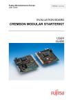
USER MANUAL HSM/UM9808 SPHERIC Demo Board Version 1.0 Philips Semiconductors SPHERIC Demo Board Version 1.0 User Manual HSM/UM9808 REVISION HISTORY Version Remarks 1.0 First release Purchase of Philips I2C components conveys a license under the Philips I 2C patent to use the components in the I2C system, provided the system conforms to the I2C specifications defined by Philips. Philips Electronics N.V. 1998 All rights are reserved. Reproduction in whole or in part is prohibited without the prior written consent of the copyright owner. The information presented in this document does not form part of any quotation or contract, is believed to be accurate and reliable and may be changed without notice. No liability will be accepted by the publisher for any consequence of its use. Publication thereof does not convey nor imply any license under patent- or other industrial or intellectual property rights. 2 Philips Semiconductors SPHERIC Demo Board Version 1.0 User Manual HSM/UM9808 USER MANUAL HSM/UM9808 SPHERIC Demo Board Version 1.0 Report No.: HSM/UM9808 Keywords Speech Recognition Digital Signal Processing DSP SPHERIC SBF1001HL I²C I²S IOM-2 Date: 15th September, 1998 3 Philips Semiconductors SPHERIC Demo Board Version 1.0 User Manual HSM/UM9808 Preface This User Manual describes a small demo board for speech recognition applications. The PCB contains a digital signal processor (DSP) called SPHERIC (Speech Recognizer IC, SBF1001HL), flash memory, SRAM and an I²C-bus I/O-expander and can be used in microcontroller systems or in conjunction with a personal computer (e.g. for demonstration purposes). 4 Philips Semiconductors SPHERIC Demo Board Version 1.0 User Manual HSM/UM9808 CONTENTS 1. General Description . . . . . . . . . . . . . . . . . . . . . . . . . . . . . . . . . . . . . . . . . . . . . 7 2. Functional Description . . . . . . . . . . . 2.1 Analog Audio Input . . . . . . . . . . 2.2 Analog Audio Output . . . . . . . . . 2.3 I²S-Interface . . . . . . . . . . . . . 2.4 IOM-2 Interface . . . . . . . . . . . . 2.5 Power Supply and Reset Generation . 2.6 Clock Generation . . . . . . . . . . . 2.7 Memories and Address Decoding . . 2.8 I²C-Bus-Interface . . . . . . . . . . . 2.9 I²C-Bus I/O-Expander. . . . . . . . . 2.10 SPHERIC User I/O - Lines . . . . . . . . . . . . . . . . . . . . . . . . . . . . . . . . . . . . . . . . . . . . . . . . . . . . . . . . . . . . . . . . . . . . . . . . . . . . . . . . . . . . . . . . . . . . . . . . . . . . . . . . . . . . . . . . . . . . . . . . . . . . . . . . . . . . . . . . . . . . . . . . . . . . . . . . . . . . . . . . . . . . . . . . . . . . . . . . . . . . . . . . . . . . . . . . . . . . . . . . . . . . . . . . . . . . . . . . . . . . . . . . . . . . . . . . . . . . . . . . . . . . . . . . . . . . . . . . . . . . . . . . . . . . . . . . . . . . . . . . . . . . . . . . . . . . . . . . . . . . . . . . . . . . . . . . . . . . . . . . . . . . . . . . . . . . . . . . . . . . . . . . . . . .8 .8 .9 .9 10 10 10 10 10 11 12 3. Appendix . . . . . . . . . . . . 3.1 Schematics of H8SM05. 3.2 Layout of H8SM05 . . . 3.3 References . . . . . . . . . . . . . . . . . . . . . . . . . . . . . . . . . . . . . . . . . . . . . . . . . . . . . . . . . . . . . . . . . . . . . . . . . . . . . . . . . . . . . . . . . . . . . . . . . . . . . . . . . . . . . . . . . . . . . . . . . . . . . . . . . . . 13 13 16 18 . . . . . . . . . . . . . . . . . . . . . . . . . . . . 5 Philips Semiconductors SPHERIC Demo Board Version 1.0 User Manual HSM/UM9808 6 Philips Semiconductors SPHERIC Demo Board Version 1.0 1. User Manual HSM/UM9808 General Description 4 LEDs PON_RSTN I²C-address I²C-Register PCF8574T I²C Optional Subboard Connector 3.3V Power Regulator and Reset Generator (POR) LP2988 I²C Level Converter I²C / PowerConnector I²C / PowerConnector The SPHERIC Demo Board consists of the basic elements for a speech recognition application as well as some optional features by keeping the size of the PCB moderate. The main components are the SPHERIC itself, flash memory, static RAM (optional), an address decoder (optional), a clock generator and divider and an I²C-bus I/Oexpander. More application specific parts are the power supply, the reset generation and the input and output connectors, which also occupy large areas on the PCB. For that reason two additional subboard connectors were introduced to allow interfacing to other application specific (customer specific) hardware. When using the subboard connector it is possible to cut the connector and/or the power supply area from the main part of the PCB. FOUT CE_SRN AddressDecoder (74LVT00) BMN CE_FLN F_RSTN Inverter BAS Flash-Memory 256k * 16 or 512k * 16 F_BYN (BC858) I/O BM MEM A19 F_RSTN F_BYN I²C Control Address Data FIN, FOUT I/O S_RSTN MIC / Line in Inverter (BC858) IOM2 I²S SRAM 128k * 8 SPHERIC S_RST Optional Subboard Connector AUXSP out I²S out I²S in Reset Button SRAM 128k * 8 AUXSP CLK CP3M MICN/MICP Clock-Oscillator 13.824 MHz Clock-Divider (:4) (74LVT74) SPH4.wmf Fig.1 Blockdiagram of the SPHERIC Demo Board 7 Philips Semiconductors SPHERIC Demo Board Version 1.0 2. 2.1 User Manual HSM/UM9808 Functional Description Analog Audio Input The MICN/MICP lines of the SPHERIC are used to interface a line input or a symmetrical or asymmetrical microphone with optional bias power supply. The diagrams below show the pins of the optional subboard connector and one jumper used for audio input connectivity. A few jumpers on CON1 are required to set up the board for either line input or microphone input. The jumper J1 (Mic) is set, if a microphone is used. The jumper setting needs not to be modified unless the signal source is to be replaced. GND 3.5mm stereo jack 1 10 R MICN 10k 33k L 100n 2k7 10k 100n 10 J1 Mic MIC0.wmf 3k3 MICP VCCA CON1 Fig.2 Board configuration of the audio input connector GND 3.5mm stereo jack 1 10 R MICN 10k 33k L 100n 2k7 10k 100n 10 J1 Mic MIC1.wmf 3k3 MICP VCCA CON1 Fig.3 Jumper configuration for asymmetrical microphone with bias supply GND 3.5mm stereo jack 1 R 10 L 33k MICN 10k 100n 2k7 10k 100n 10 J1 Mic MIC2.wmf 3k3 MICP VCCA CON1 Fig.4 Jumper configuration for symmetrical microphone with shielded cable and bias supply GND 3.5mm stereo jack 1 10 R MICN 10k 33k L 100n 2k7 10k 100n 10 LINE3.wmf J1 Mic 3k3 MICP VCCA CON1 Fig.5 Jumper configuration for line input (for use with mono plug) 8 Philips Semiconductors SPHERIC Demo Board Version 1.0 2.2 User Manual HSM/UM9808 Analog Audio Output The AUXSP line out of the SPHERIC is used to either interface an active PC sound system or a high impedance headphone. The diagram below shows the corresponding pins of the optional subboard connector. The jumpers have to be set once for the output device. L 3.5mm stereo jack 1 4u7 R 330 AUXSP 1k GND AUXSP0.wmf CON2 Fig.6 Board configuration of the audio output connector L 3.5mm stereo jack 1 4u7 R 330 AUXSP 1k GND AUXSP1.wmf CON2 Fig.7 Jumper configuration for output on both stereo channels (AC coupling) L 3.5mm stereo jack 1 4u7 R 330 AUXSP 1k GND AUXSP3.wmf CON2 Fig.8 Jumper configuration for output on both stereo channels (DC coupling) 2.3 I²S-Interface There are two optional connectors foreseen on the SPHERIC Demo Board to interface I²S signals. The input can be configured to SD0 or SD1 pin of the SPHERIC (jumper on CON6 at pins 3 and 4 or pins 1 and 2), the output is fed directly to the connector. The SPHERIC operates as I²S slave device and gets the serial clock (SCK) and word select (SWS) from an external master. The I²S interface can be used alternatively to the analog audio codec or the digital IOM2 interface. The mode is selected by the software running on the SPHERIC. Optional subboard connector CON7 CLK 1 I²S input connector 1 I²S output connector 1 2 3 4 SDIN1 1 SDIN0 SDOUT SWS SCK CON6 CON12 CON13 I2S.wmf Fig.9 Diagram of the I²S connectors 9 Philips Semiconductors SPHERIC Demo Board Version 1.0 2.4 User Manual HSM/UM9808 IOM-2 Interface The IOM-2 lines of the SPHERIC are fed to four pins of the optional subboard connector. The lines IOM2_DD and IOM2_DU have an 1k pull-up resistor each. The IOM2 interface can be used alternatively to the analog audio codec or the digital I²S interface. The mode is selected by the software running on the SPHERIC. IOM2_FSC IOM2_DD IOM2_DCL IOM2_DU 1 CON3 1k 1k DVCC IOM2.wmf Fig.10 Pin assignment of the IOM2 interface connector CON3 2.5 Power Supply and Reset Generation The SPHERIC Demo Board is a pure 3.3V design. To ease interfacing, a voltage regulator with built-in power on / power failure reset generation is used. The regulator allows interfacing to a 5V power supply. Even if the regulator is not used (bypassed with jumper J2, pin 1 to pin 2) the circuit is used to monitor the incomming 3.3V and to generate the reset signal. If the input voltage is too low, the reset signal out of the regulator remains active. After approx. 70 ... 100 ms after power-up the reset is deasserted. The reset out of the regulator is fed via a jumper on the subboard connector CON5 (pin 23 to pin 21). The reset button is connected directly to the inverting transistor (see Fig.11 on page 11). The power consumption of the SPHERIC demo board depends on the application running on the SPHERIC. The input current has been measured to approx. 45 mA (after reset) to 90 mA (during flash erase operation). 2.6 Clock Generation A (pre-) programmable 3.3V crystal oscillator is used to generate the 13.824 MHz clock for the SPHERIC. This clock is also available on the subboard connector. The clock for the SPHERIC audio codec is derived with a divider (div. by 4 using the two flip-flops out of the 74LVT74). 2.7 Memories and Address Decoding Two types of flash memories are foreseen on the SPHERIC Demo Board. Either 256k16 or 512k16 flashes can be used (e.g. AM29LV400 or AM29LV800). Two resistors (R19 and R20) need to be assembled according to the flash type: R19 = 0R and R20 = OPEN for AM29LV800; R19 = OPEN and R20 = 0R for AM29LV400. For the SRAM a TSOP32F package is used. At least three memory types seem to be suitable with a memory size of either 128k8 or 64k8: KM68V1000BLTI-7L (Samsung;128k8); TC55V1001STI (Toshiba;128k8); KM68V512 (Samsung; 64k8). SRAM need only to be assembled, if it is required by the software running on the SPHERIC. Since using a simple address decoding logic the memories can be accessed at baseaddresses of multiples of the memory size. The flash memory is located starting at address 0x00000, the SRAM starts at 0x80000. 2.8 I²C-Bus-Interface The I²C-bus interface of the SPHERIC Demo Board is equipped with level shifters (two fieldeffect transistors) to allow directly the operation with 5V level I²C-bus applications. It is also possible to operate the SPHERIC Demo PCB with 3.3V external I²C-bus levels without modifications. Via the I²C-bus it is possible to access an I/O-expander (see below) and the SPHERIC. After power-up the SPHERIC has a default hard-wired device address (1Ah [7bit notation]; 34h [8bit notation]; ´0011010´ bin, to be followed by R/W control bit). This address can be modified in two ways: when boot mode (BM) = 1, the device address is read out of the Y-MEM at address 0x00001, furthermore the software running on the SPHERIC is able to modify the register containing the device address. For details see SPHERIC datasheet. 10 Philips Semiconductors SPHERIC Demo Board Version 1.0 2.9 User Manual HSM/UM9808 I²C-Bus I/O-Expander An 8 bit I²C-bus I/O-expander is used for extended interfacing to the SPHERIC and the flash memory features. It is possible to reset the flash memory as well as the SPHERIC and to set the SPHERIC boot mode. The default after power-on is to boot from flash memory; BAS = 1; BM = 0). Some I/O-lines are free for future use (ports 7, 3, 2 and 1) and can be assigned to SPHERIC I/O lines via jumper settings (see below). The I²C-slaveaddress of the device can be set via jumpers (address bits A2 and A1) and resistors (R6 and R14 for bit A0). This allows the operation of multiple SPHERIC Demo Boards on one I²C-bus. The following tables show the jumper and resistor settings, the corresponding slaveaddress and the assignment of the I/O-lines. TABLE 1 Jumper settings for the I²C slaveaddress of the PCF8574T A2 A1 A0 Slaveaddress CON5 pin 25 to CON4 pin 1 (DGND) CON5 pin 26 to CON4 pin 2 (DGND) R6 (pull-up) R14 (pull-down) 7bit notation 8bit notation closed (low) closed (low) open 0R 20h 40h closed (low) closed (low) 10k open 21h 42h closed (low) open (high) open 0R 22h 44h closed (low) open (high) 10k open 23h 46h open (high) closed (low) open 0R 24h 48h open (high) closed (low) 10k open 25h 4Ah open (high) open (high) open 0R 26h 4Ch open (high) open (high) 10k open 27h 4Eh TABLE 2 I/O-line assignment of the PCF8574T Bit / Port 7 6 5 Value Signal Name [option] 80h 40h n.c. F_RSTN [F_BYN] 4 3 2 1 0 20h 10h 08h 04h 02h 01h BAS BMN n.c. [FOUT0] n.c. [FIN2] n.c. [FIN1] S_RSTN After power-up the default for the PCF8574T I/O-lines is high (FFh; high via internal pull-up; see note below concerning SPHERIC input cell pull-down resistors). This results in external (flash) memory boot-mode (BM=0) and cold start (BAS=1: bootstrap procedure is started at ZMEM address 0xF00). To invoke a reset of the SPHERIC (cold or or warm start, ext. memory boot or I²C boot), the PCF8574T should be read and rewritten with the desired settings for the bits BMN and BAS (the other bits should get the previous read value). Furthermore the databyte should be send three times so that for the S_RSTN line a low active reset pattern is generated. This can be done in one I²C transmission. Read from PCF8574T via I²C bus: S 27h R databyte (e.g. FFh) P [S: start condition; R: read operation] [P: stop condition; W: write operation] Write reset pattern to PCF8574T via I²C bus: S 27h W FFh FEh FFh P BAS=1; BMN=1 (BM=0): S 27h W EFh EEh EFh P BAS=1; BMN=0 (BM=1): S 27h W DFh DEh DFh P BAS=0; BMN=1 (BM=0): S 27h W CFh CEh CFh P BAS=0; BMN=0 (BM=1): cold start; boot from external (flash) memory cold start; waiting for I²C download of the boot program warm start (restart current program at ZMEM 0x000) warm start (restart current program at ZMEM 0x000) 11 Philips Semiconductors SPHERIC Demo Board Version 1.0 2.10 User Manual HSM/UM9808 SPHERIC User I/O - Lines The SPHERIC user I/O-lines are fed to the optional subboard connector. The outputs are also fed to four LEDs which are located in the connector area. A high signal on the pins will activate the appropriate LED. FOUT3 can be used to reset the flash memories if a jumper is set on CON5. This offers the opportunity to invoke a flash reset via software running on the SPHERIC. FOUT0, FIN1 and FIN2 can be fed to port 3, port 1 and port 2 of the PCF8574 via jumper on the subboard connector CON5. Optionally the status of the flash memory (F_BYN at FIN0) can be read back via port 7 of the PCF8574 when an appropriate jumper is set. CON5 Reset button 1 7 820 FOUT3 820 FOUT2 820 820 Power Regulator 3.3V 8 FOUT1 FOUT0 PON_RSTN IREQ 8574_P7 F_BYN (FIN0) F_RSTN (8574_P6) FOUT3 BAS (8574_P5) FOUT2 BMN (8574_P4) FOUT1 8574_P3 FOUT0 8574_P2 FIN2 8574_P1 FIN1 S_RSTN (8574_P0) CON8 SCL 3 25 26 2 1 2 Jumper position for VCC (external) = 3.3V BM 10k VCCD 47k BC858 1 4* 10k SDA3.3 10k open VCC3.3 VCC3.3 Level Converter VCCD Decoupling VCCA SCL3.3 1 CON9 BC858 S_RST GND 1 47k 8574_INTN 8574_A2 8574_A1 8574_A0 23 Jumper position for VCC (external) = 5.0V VCC VCCD 21 J2 SDA 3n3 CON4 I²C-bus and power supply connectors Optional subboard connector SUB.wmf Fig.11 Optional subboard connector for power supply, I²C-bus and control I/O Note 1: To adapt different LEDs to the board the resistors R32 ... R35 can be reduced down to 470 ohms. A further reduction leads to a current of more than 3 mA (max. current for SPHERIC FOUT cell). Red low current LEDs are prefered due to their higher efficiency. Note 2: Since SPHERIC has pull-down resistors at most of its input cells it is required to add pull-up resistors when using high ohmic sources (for logical high level) like the PCF8574T. For the signal BAS (PCF8574T bit 5) an additional 4k3 resistor is mounted on the PCB to ensure stable reset and boot behaviour. 12 Philips Semiconductors SPHERIC Demo Board Version 1.0 3. 3.1 User Manual HSM/UM9808 Appendix Schematics of H8SM05 13 Philips Semiconductors SPHERIC Demo Board Version 1.0 User Manual HSM/UM9808 14 Philips Semiconductors SPHERIC Demo Board Version 1.0 User Manual HSM/UM9808 15 Philips Semiconductors SPHERIC Demo Board Version 1.0 3.2 User Manual HSM/UM9808 Layout of H8SM05 16 Philips Semiconductors SPHERIC Demo Board Version 1.0 User Manual HSM/UM9808 17 Philips Semiconductors SPHERIC Demo Board Version 1.0 3.3 User Manual HSM/UM9808 References [1] Datasheet SBF1001HL (Speech Recognizer IC, SPHERIC); May 26, 1998 Philips Semiconductors [2] Datasheet PCF8574; September 1994 Philips Semiconductors [3] User Manual HSM/UM9709, SPHERIC Evaluation Board Philips Semiconductors, Systems Laboratory Hamburg [4] User Manual HSM/UM9713, SPHERIC Controller Board Philips Semiconductors, Systems Laboratory Hamburg 18