1
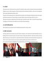
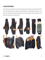
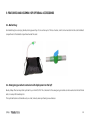
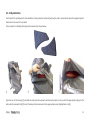
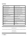
ver si on2. 0 En gl is h GTO THANK YOU! We would like to thank you for having chosen one of our products, and we invite you to read this important document, the User Manual for the harness. Please pay special attention to the two most important paragraphs, regarding: Insertion of the reserve parachute. The reserve parachute is a piece of equipment that may save your life. It must be inserted so that it works correctly when it is required, whether this happens in two days time, or two years from now. Adjusting the harness. The harness forms the connection between the pilot and the paraglider, and it is an essential component in optimizing performance and the pleasure of flying. A bad harness that is well adjusted may enable you to fly well, but a good harness that is badly adjusted may put you off flying altogether. We are confident that this harness will give you great comfort, control, performance and enjoyment in flight. We are conscious of the fact that reading an instruction manual is not an exciting experience. However, please remember that this product is not a citrus juicer or a mobile phone, and that correct use of the harness helps reduce the risk of flying accidents. This manual contains all the information necessary to assemble, adjust, fly and store your harness. Thorough knowledge of your equipment will improve your personal safety and your level of flying. Team Woody Valley SAFETY NOTE By the purchase of Woody Valley equipment, you are responsible for being a certified paraglider pilot and you accept all risks inherent with paragliding activities including injury and death. Improper use or misuse of equipment greatly increases these risks. In no case shall Woody Valley or Woody Valley equipment resellers be held liable for personal or third party injuries or damages under any circumstances. If any aspect of the use of our equipment remains unclear, please contact your local reseller or Woody Valley directly. INDEX 1- GENERAL INFORMATION ..................................................................................................................................................................................... 1 1.1- CONCEPT............................................................................................................................................................................................................................................... 2 1.2- X-ALPS GTO PROTECTION ................................................................................................................................................................................................................. 2 1.3- MINI T-LOCK SYSTEM .......................................................................................................................................................................................................................... 2 1.4- S.O.S. LABER ....................................................................................................................................................................................................................................... 3 2- BEFORE USE......................................................................................................................................................................................................... 3 2.1- RESERVE PARACHUTE .......................................................................................................................................................................................................................... 4 2.1.1- Connecting the deployment handle to the deployment bag ........................................................................................................................................ 4 2.1.2- Connecting the reserve parachute to the harness ......................................................................................................................................................... 5 2.1.3- Inserting the reserve parachute into the harness .......................................................................................................................................................... 7 2.1.4- Extracting the reserve parachute ....................................................................................................................................................................................... 8 2.2- FRONT RESERVE PARACHUTE............................................................................................................................................................................................................... 9 2.2.1- Connecting the deployment handle to the deployment bag ........................................................................................................................................ 9 2.2.2- Connecting the front emergency parachute to the harness .................................................................................................................................... 10 2.2.3- Inserting the front emergency parachute ..................................................................................................................................................................... 11 2.2.4- Extracting the front reserve parachute.......................................................................................................................................................................... 13 2.2.5- Back storage pocket............................................................................................................................................................................................................. 14 2.3- HARNESS ADJUSTMENTS .................................................................................................................................................................................................................. 15 2.3.1- Adjusting seat and back position ..................................................................................................................................................................................... 16 2.3.2- Shoulder strap adjustment ................................................................................................................................................................................................ 17 2.3.3- Chest strap adjustment ...................................................................................................................................................................................................... 18 2.3.4- Leg strap adjustment .......................................................................................................................................................................................................... 18 2.3.5- Stabilizer ................................................................................................................................................................................................................................. 19 2.3.6- ABS adjustment .................................................................................................................................................................................................................... 19 2.3.7- Leg cover................................................................................................................................................................................................................................. 20 2.3.8- Speed-bar adjustment ........................................................................................................................................................................................................ 21 3- FLYING WITH THE X-ALPS GTO HARNESS ........................................................................................................................................................ 22 3.1- PRE-FLIGHT CHECKS ......................................................................................................................................................................................................................... 22 3.2- POCKETS ............................................................................................................................................................................................................................................ 22 3.3- WATER BLADDER ............................................................................................................................................................................................................................... 24 3.4- FRONT BALLAST INSTALLATION AND USE OF THE COCKPIT .............................................................................................................................................................. 24 3.5- INSTALLING THE LOWER BALLAST ..................................................................................................................................................................................................... 26 3.6- FLYING ABOVE WATER ....................................................................................................................................................................................................................... 27 3.7- AERO-TOWING HOOK ......................................................................................................................................................................................................................... 27 3.8- LANDING WITH THE X-ALPS GTO .................................................................................................................................................................................................... 28 3.9- HARNESS DISPOSAL .......................................................................................................................................................................................................................... 28 3.10- RULES OF CONDUCT IN NATURAL ENVIRONMENT ............................................................................................................................................................................ 28 4- PACKING THE HARNESS .................................................................................................................................................................................... 29 5- FEATURES AND ASSEMBLY OF OPTIONAL ACCESSORIES .............................................................................................................................. 30 5.1- BALLAST BAG .................................................................................................................................................................................................................................... 30 5.2- EMERGENCY PARACHUTE CONTAINER WITH DEPLOYMENT ON THE LEFT ......................................................................................................................................... 30 5.3 - SIDE PROTECTION ............................................................................................................................................................................................................................. 31 6- MAINTENANCE AND REPAIRS ........................................................................................................................................................................... 32 7- DATI TECNICI ...................................................................................................................................................................................................... 33 1- GENERAL INFORMATION This equipment should contain: Harness Carbon seat plate Composite foot plate Hook-in karabiners Emergency parachute deployment handle Two spare elastic loops for fastening the emergency parachute container Three step speed-bar Dorsal protection The optional accessories available are: Ballast bag, with carrying handle, tube, and drainage tap Emergency parachute with deployment on left-hand side Front parachute Side protection 1 1.1- Concept Following the success of the first model, the new version of the X-Alps GTO includes a number of improvements and new technical features designed to improve the safety and pleasure of flying, while at the same time maintaining the lightness, comfort and control requirements that have always distinguished Woody Valley products. The geometry of the load-bearing structure, combined with its active piloting, render it fully capable of satisfying the needs of a wide range of pilots, while even ensuring ease of transport thanks to its exceptional lightness, and all in full compliance with the LTF protocol. Leg-straps and chest straps are fitted with the ‘‘GET-UP safety system,’’ and with the innovative ‘‘Mini T-Lock system’’ that prevents the pilot from slipping out of the harness in the case that he or she has forgotten to fasten the leg straps. 1.2- X-ALPS GTO protection The X-ALPS GTO harness is fitted with new LTF-certified dorsal protection with a 12 cm layer of foam. 1.3- Mini T-Lock System The Woody Valley team has renovated its previous DRC system by developing a new mechanism that’s aimed at addressing the issue of forgetting to fasten the chest and leg straps. The system includes two females buckles attached to a load bearing carabiner, and another attached to the leg-cover’s closure element; the central element that allows for the buckles to be fastened is attached to the leg strap: in this manner, in order to properly close the leg-cover, the pilot is required to grasp the leg strap, and is thus reminded to close it. The new system offers improved manageability and a more intuitive interface, and can even be used even while wearing gloves. 2 1.4- S.O.S. Laber This label, coloured red with white lettering, is readily visible in a pocket on the right shoulder-strap padding. It is easy to pull out, and it is fastened to the harness to prevent it from being lost. On the back of this label, you can write the information that you think should be given to rescue personnel in case of accident. 2- BEFORE USE The X-ALPS GTO harness is supplied with dorsal protection and a polycarbonate plate, which have already been assembled by the manufacturer. The emergency parachute must be fitted with great care by a qualified professional, such as your instructor. Only after this operation should the pilot adjust the harness for optimum comfort. 3 2.1- Reserve parachute The new X-Alps GTO provides for two configurations: 1. with the parachute container in the classic position, beneath the seat at the front; 2. with a second parachute lodged beneath the cockpit at the front (optional). The lower reserve parachute must be attached to the harness before being inserted into the built-in container, which has been modified with an elastic bulkhead that allows for parachutes of different volumes to be inserted in stable positions. This connection withe the harness takes the form of a dual bridle fixed to the harness at shoulder height, for better load distribution and to ensure a correct landing position in the case that the reserve parachute is deployed. This helps reduce the risk of injury to a minimum. The reserve chute bridle has a large central loop coloured red, and this is reinforced with a cover in Cordura 500. At the extremity of the loop, there is a Velcro band which enables the link with the reserve parachute to be held firmly in position. 2.1.1- Connecting the deployment handle to the deployment bag X-ALPS GTO is supplied with a handle for reserve parachute extraction. It is identified with the n. 6; this handle alone should be used for this purpose. The black loop attached to the handle itself should be passed into the loop on the deployment bag, and then the entire handle should be passed through its own loop and pulled tight. For easier extraction, the loop attached to the deployment bag should be positioned laterally with respect to the centre of the reserve parachute. If your deployment bag does not have this loop, please contact the retailer from whom you purchased the reserve parachute. 4 2.1.2- Connecting the reserve parachute to the harness There are three different methods of attaching the reserve parachute bridle to the harness bridle. First system: Use a screw-lock karabiner with a breaking strength of at least 2400 kg. In this case, the bridles should be held in position within the karabiner using elastic bands, to prevent the karabiner from rotating and taking the strain laterally instead of vertically. The karabiner’s screw-lock should be tightly screwed shut to avoid any possibility of it opening accidentally. This type of connection can absorb a higher opening shock than the second system, and for this reason this is without doubt the recommended system. Second system: The reserve parachute bridle is passed through the loop at the end of the harness reserve parachute bridle. The reserve parachute itself is then passed through the large loop in the reserve parachute bridle. This connects the two bridles. The loops should be pulled as tight as possible to avoid any chance of dangerous friction developing between the two bridles during the shock caused when the reserve parachute opens. To ensure that the link between the two bridles remains tight, remember to fasten the knot using the Velcro strip on the harness reserve parachute bridle. 5 Third system: If you are using a reserve parachute with directional control and dual bridle, or if your reserve parachute in any case has a double-riser bridle, it can be connected to the harness using the two loops positioned at the base of the harness bridle, near the padded shoulder straps. In this case, the harness’ reserve parachute bridle will not be used, and so it should be folded, fastened using two elastic bands, and positioned under the cover behind the pilot’s neck. The two connections should be made using screw-lock karabiners with a breaking strength of at least 1,400 kg. In any case, it is important to verify that the length of the bridle is sufficient to position the reserve parachute inside the harness pocket, and that there is sufficient play to enable the parachute to be taken out of the pocket without causing the reserve parachute deployment bag itself to open during extraction. 6 IMPORTANT: -To prevent anomalous lateral loads, the bridle should be attached to both the loops on the shoulder straps. Not to just one of them. 2.1.3- Inserting the reserve parachute into the harness Insert the reserve parachute into the pocket of the harness, so that the handle is visible and facing outwards, and the loop connecting the handle to the deployment bag is facing upwards. 7 Thread a thin cord (such as paraglider riser cords) through each elastic loop. This will help close the pocket. Thread the elastic loops into the smallest of the eyelets on the pocket flaps. Close the flaps following the order shown in the photographs below. Push the metal pins on the handle into the elastic loops and under the transparent cover. It is essential to remove the cords after this operation. The cords should be pulled out slowly in order not to damage the elastic loops by excessive friction. Lastly, the handle should be positioned under the elastic cover. IMPORTANT: -Every new combination of reserve parachute and harness or the external container assembled for the first time should be tested by an official harness or reserve parachute dealer, or by a flying instructor. Deployment of the reserve parachute should be perfectly feasible from the normal flying position. 2.1.4- Extracting the reserve parachute It is vital to feel periodically for the position of the reserve parachute deployment handle during normal flight, so that the action of reaching for the reserve parachute handle becomes instinctive in an emergency. In emergency situations, the deployment procedure is as follows: Look for the reserve parachute handle and grasp it firmly with one hand. 8 Pull the handle outwards in order to extract the reserve parachute from the harness container. Look for a clear area, and, in a continuous motion, throw the reserve parachute away from yourself and the paraglider. After the reserve parachute has opened, avoid entanglement by pulling in the paraglider, gripping at least one D line, or the brake lines, in order to collapse the glider. On landing, adopt an upright body position, and ensure that you perform a PLF (Parachute Landing Fall) to minimize the risk of injury. 2.2- Front reserve parachute The emergency parachute container is in the ventral section. The container was designed for very light emergency parachutes, with a lower volume than standard chutes. The parachute has to be connected to the bridle provided before inserting it into the ventral container. The bridle splits into two straps which are fastened to the main harness karabiners. With this type of link between the emergency parachute and the harness, the emergency parachute can be deployed from left or from right. 2.2.1- Connecting the deployment handle to the deployment bag X-ALPS is supplied complete with the handle for parachute deployment, marked as n° 13; this deployment handle only should be used. The black loop on the handle should be put through the loop attached to the deployment bag, and then the entire handle should be passed through the handle’s loop in order to link the two. In this harness, to facilitate deployment, we recommend linking the handle to the loop situated in the central part of the deployment bag. If your deployment bag does not have this loop, please contact your emergency parachute retailer. 9 2.2.2- Connecting the front emergency parachute to the harness There are two methods for connecting the emergency parachute bridle to the harness risers. First system: Use a karabiner with a screw collar and a breaking strength of at least 2400 kg. In this case, the emergency parachute risers should be held in position within the karabiner using elastic bands, to prevent the karabiner from rotating into a lateral position which could cause it to undergo a dangerous lateral stress in the case of deployment. The screw collar should be tightened very firmly to prevent accidental opening. This type of connection can withstand a higher shock on deployment than the second system, and it is without doubt the best system to use. Second system: The reserve parachute bridle is passed through the loop at the end of the harness reserve parachute bridle. The reserve parachute itself is then passed through the large loop in the reserve parachute bridle. This connects the two bridles. The loops should be pulled as tight as possible to avoid any chance of dangerous friction developing between the two bridles during the shock caused when the reserve parachute 10 opens. To ensure that the link between the two bridles remains tight, remember to fasten the knot using the Velcro strip on the harness reserve parachute bridle. 2.2.3- Inserting the front emergency parachute Fasten the emergency parachute bridle using the two Velcro strips inside the parachute container, ensuring that the two loops leading to the main karabiners are on opposite sides and emerge from the cockpit symmetrically, therefore with the same length. These two loops also make it possible to adjust the height of the container. We recommend fastening the Velcro as shown in the photo, in other words with the edge at the extremity of the container. If this is not satisfactory, remove the emergency parachute and repeat the steps as described below. Then carefully arrange the bridle inside the container. 11 Insert the parachute into the harness container so that the deployment handle is visible and facing outwards, and with the loop that connects the handle to the deployment back facing upwards. Thread a thin cord (such as a paraglider shroud line) into each elastic loop. This will make it easier to close the container. Insert the elastic loops into the smaller grommets (smaller with respect to the others on the edge of the container). Close the flaps in the order shown in the drawings/photos below. Insert the metal pins into the elastic loops and insert the handle beneath the fabric flaps. The cord must absolutely be removed at the end of this phase, and must be extracted slowly in order to avoid damaging the elastic loops due to excessive friction between the parts. Once the parachute has been inserted into the container, it must be secured to the harness by connecting the loops on the restraint ropes to the carabiners: the loop on the right always remains fastened to the corresponding carabiner, while the loop on the left must be connected when closing the harness before each takeoff. 12 The container is connected using the special buckles and must be fastened to the leg-cover using the zipper. The parachute container houses the instrument compartment, which is also connected using a zipper. IMPORTANT: - Each new combination of emergency parachute and harness or emergency parachute container to be assembled for the first time should be checked to ensure that the emergency parachute can be correctly deployed, by an official harness or emergency parachute dealer, or by a flight instructor. Emergency parachute deployment should be perfectly feasible from the normal flying position. -Before takeoff, always check to make sure that both of the front parachute’s loops are attached to the corresponding carabiners. 2.2.4- Extracting the front reserve parachute It is vital to feel periodically for the position of the reserve parachute deployment handle during normal flight, so that the action of reaching for the reserve parachute handle becomes instinctive in an emergency. In emergency situations, the deployment procedure is as follows: Look for the reserve parachute handle and grasp it firmly with one hand. 13 Pull the handle outwards in order to extract the reserve parachute from the harness container. Look for a clear area, and, in a continuous motion, throw the reserve parachute away from yourself and the paraglider. After the reserve parachute has opened, avoid entanglement by pulling in the paraglider, gripping at least one D line, or the brake lines, in order to collapse the glider. On landing, adopt an upright body position, and ensure that you perform a PLF (Parachute Landing Fall) to minimize the risk of injury. 2.2.5- Back storage pocket To reach the back storage pocket, first of all you have to completely open the zip on the aerodynamic part of the harness towards the rear, and then turn over the aerodynamic tip. This will provide access to the storage pocket, which is opened by means of another zip. This pocket was specially designed with a size and shape suitable for a pair of telescopic walking poles (maximum length 67 cm in the L size), as well as the rucksack and a windcheater jacket: in other words, the equipment required by a hiker. The tips of the telescopic walking poles should be inserted into the metal grommets at the bottom of the pocket, as shown in the photo. To close the pocket and the aerodynamic part of the harness, just close the two zips. 14 IMPORTANT: - Overfilling the back pocket could prevent the correct inflation of the aerodynamic part of the harness. - Arrange the objects evenly throughout the entire space of the dorsal pocket, so that the harness profile is not deformed. - Do not place any objects inside between the inflatable section and the pocket. - Remember to close the zip of the aerodynamic part of the harness, in order to ensure correct inflation. 2.3- Harness adjustments X-ALPS GTO is supplied already adjusted to a standard ergonomic setting, apart from adjustments required for pilot height. Therefore, for the first flight we recommend adjusting the harness for height alone, leaving the other settings unchanged, because they have proved to be satisfactory for the vast majority of pilots. If you wish to change the other settings, remember that you can always return to the factory settings by making reference to the red marks on all adjustment straps. Please remember that the size of your X-ALPS GTO harness should be chosen according to your height, and not according to seat width. Unlike a harness based on a fundamentally seated position, in which the height of the seat back is not essential for good comfort, in this harness the pilot flies in a more supine position, and so the height of the back support is very important for good comfort and a correct flying position. Therefore it is important to select the right size, in particular as regards the height of the seat back, without worrying about the seat 15 width. To adjust the harness to the optimum position, we recommend simulating flight position by hanging the harness from a suitable fixed point, therefore with all the items that you normally carry in flight inserted into the back pocket. IMPORTANT: - Before making any adjustments, the emergency parachute must be inserted. - Every adjustment must be made symmetrically on both sides. - Every adjustment strap has to be tight. 2.3.1- Adjusting seat and back position This photo shows how the lateral adjustments are arranged, and the many points at which the pilot is actually supported, from the upper back down to the lumbar area. All these adjustments improve pilot support and enable the harness to be adjusted to all back types. In the detail photo, adjustment n° 1 changes the angle between thighs and back (seat depth), distributing load between seat and the lumbar area and thus improving pilot comfort. Adjustment n° 3 is that which is principally used to alter the angle between the torso and the vertical. Adjustments n° 2 and n° 4 are useful for fine back adjustments, but they are secondary adjustments that improve contact between the harness back and the pilot’s back, improving support and comfort. 16 If you wish to work on the adjustments, the first strap should be loosened before adjusting the main strap to the point of optimum comfort. Once you have completed these steps, tighten the covering strap again in order to lock the adjustment setting. 2.3.2- Shoulder strap adjustment Adjustment of the shoulder pads compensates for the variation in pilot height and the adjustment buckle is located in front of the pilot's shoulder. The shoulder pads also bear part of the weight of the upper body for improved comfort. We recommend adjusting the shoulder pads so that they fit against your shoulders without being too slack or too tight. 17 2.3.3- Chest strap adjustment The chest strap which controls the distance between the two karabiners can be adjusted from 40 to 55 cm. For the first flight with X-ALPS GTO, we suggest setting the chest strap to the minimum length, then locating the preferred length in flight by means of gradual adjustment. When the chest strap is shorter and tighter, stability is greater. An excessive distance between karabiners does not improve glider performance, and tightening the chest strap excessively may exacerbate the "twist" effect that may follow an asymmetric collapse of the sail. 2.3.4- Leg strap adjustment The roots of the leg straps are positioned high, a characteristic of the Get-Up system, and this ensures great freedom of movement for the legs. Generally, the factory settings are correct. If it is difficult to enter the harness after launch, we suggest tightening the leg strap adjustment under the seat. This makes it easier for the pilot to enter the harness after launch without having to let go of the paraglider’s control handles. 18 2.3.5- Stabilizer This small but important adjustment makes it possible to stabilize the harness when you exert pressure on the speed-bar, preventing excessive tilt of the back. Its mode of operation is very simple: when you push the speed-bar, this small plastic buckle blocks the shoulder-straps at the point at which they slide in the chest strap, making the entire strap system more rigid and improving overall harness stability. This adjustment is correctly set by the manufacturer. 2.3.6- ABS adjustment This adjustment affect flying performance. The looser it is, the less stable the harness becomes, and therefore the more sensitive to pilot movements. Vice versa, the tighter it is adjusted, the more stable the harness becomes, requiring more pronounced pilot movements in flight. X-ALPS GTO is supplied with this adjustment set to a position that is suitable for most pilots. If you wish to change this setting, take great care and make very small changes, just a few millimeters every time. Ensure that adjustments are made with absolute symmetry. 19 2.3.7- Leg cover The leg cover has also been optimized. In particular, the closure has been improved with the inclusion of a magnet that even keeps it closed at high speeds, thus eliminating the ‘‘flapping’’ phenomenon. The geometry of the front leg-cover’s automatic closing system has also been modified in order to facilitate the insertion of the legs after takeoff. The leg cover can be adjusted for length by means of four small white spheres inside the cover, shown in the illustration below. The footrest is set for an approximately 90° ankle angle, the most natural and comfortable. Leg cover length can be extended or shortened according to the pilot’s requirements, maintaining symmetry of settings. 20 2.3.8- Speed-bar adjustment X-ALPS GTO includes a three-step speed-bar, made with slim fabric webbing to decrease harness weight. The length of the speed-bar system should be adjusted only after the optimum harness adjustments have been completed. To set the speed-bar correctly, the pilot should sit in the harness in a simulator, hook in to the paraglider risers, and, with a helper supporting the risers, adjust the length of the speed-bar straps. When released, the footrest should be no more than 10 cm below the frontal part of the harness. Shortening the cord excessively could cause the speed-system to be constantly under tension and therefore unintentionally operational during the flight. It is safer to begin by launching with the speed-bar a little too long, shortening it progressively on the next flights. It is important to perform each adjustment symmetrically, in other words equal on both sides. If you wish to change the footrest, we can inform you that this harness can be used with all normal types of speed-bar. The footrest cords should be threaded first through the loops fixed to the elastic cord at mid-seat (1), on through the pulleys near the back corners of the seat (2), and then up to the fastening points on the paraglider risers, passing through the small grommets in the leg cover (3). In addition, the two elastic cords that Woody Valley supplies with all its speed-bar/footrests have to be fitted. These elastic cords (4) should be fastened, with simple knots, to the two loops on the underside of the footrest. This ensures that the speed-system is always properly extended and ready for use. 21 3- FLYING WITH THE X-ALPS GTO HARNESS 3.1- Pre-flight checks For maximum safety, use a complete and thorough sequence of pre-flight checks, and use the same sequence of checks every flight. Ensure that: ensure that the two chest-strap buckles and the ‘‘Mini T-Lock system’’ are fastened. Take great care in the case of ice or snow, and always wipe the buckles clean of snow and ice before fastening them; the bridle loops are correctly inserted into the karabiners; all pockets and zips are closed; the paraglider is correctly hooked to the harness, and that both karabiners are locked closed by the respective locking mechanism; the speed-bar is correctly fitted to the paraglider; 3.2- Pockets The X-ALPS GTO harness has a roomy back pocket and various side pockets. One of the latter is situated close to the main karabiners; it is ideal for a radio or mobile phone, and it is fitted with a safety loop. The harness has another two large side pockets. The instrument deck was designed so that it can easily be removed from the cockpit, so that the pilot can have the instruments with him or her at all times, for briefing, or to protect them from the pressure that may be caused by folding the harness. The instrument deck has a zip that provides access to the ballast compartment during flight, and enabling it to be removed completely after having landed. In addition, it has a 2-millimetre neoprene cover that protects the instruments from accidental blows. When the container has been removed from the harness, the pilot can open another zip-closing pocket at the base of the instrument deck. 22 23 3.3- Water bladder The X-ALPS GTO harness was designed specifically for use with a water bladder. Place the water bladder as shown in the photo, in the respective location positioned in the rear storage pocket. Push the tube through the eye on the harness. The tube should run below the Lycra cover of the shoulder strap, emerging from the eye as shown in the photo. 3.4- Front ballast installation and use of the cockpit The cockpit has been completely redesigned: it has an aerodynamic shape integrated into the leg-cover, it can be removed using a zipper and can even be combined with two other elements beneath the instrument compartment: a 3.5 L ballast (standard) or a second parachute (optional). In order to render the cockpit more stable for movements on the ground, a plastic buckle has been added to the chest strap, which limits the changes in inclination and prevents it from falling over. If you decide to use, or not, the ventral ballast container, the cockpit has to be adjusted so that during flight it does not impede visibility or impair comfort. There is a triangular piece of strapping sewn onto both sides of the container, with a buckle for fastening and adjustment. By 24 adjusting the buckle position and strap length, the designed height and angle of the surface on which the instruments rest during flight can be adjusted. The ballast discharge tube has been installed in such a way so that it leads into the right-hand pocket, from which the tap can be easily extracted and operated. The procedure for installing the ballast is illustrated below: 1 2 3 4 5 6 25 Open the zipper beneath the instrument compartment (1) to access the ballast lodging (2). Next, open the Velcro over the discharge tube’s outlet hole (3) and insert the tube (4). There is a second through-hole (5) inside the harness, which allows the discharge tube to be inserted into the external pocket, where it can be hidden and extracted whenever necessary (6). 3.5- Installing the lower ballast The new GTO offers the possibility of positioning a 4.5 liter ballast beneath the seat. In order to take advantage of this feature, just install the ballast in the container beneath the seat, insert the discharge tube into the appropriate hole in the container and feed it through the hole on the lower left of the harness so that it ends up in the dedicated external pocket. In this manner the tap can be easily accessed by the pilot on the left-hand side of the harness while in flight. 1 2 3 The ballast lodging is located beneath the seat. Open the zipper to access (1) the lodging, insert the discharge tube into the through-hole on the right (2) and install the ballast (3). 26 4 5 6 Insert the tube into the slot on the right hand side (4) and slide it through the hole that leads from the inside of the harness (5) to the pocket on the outside, from which the tap can be extracted for drainage (6). 3.6- Flying above water There are no specific problems connected to flying above water using an X-ALPS GTO harness, but in any case, landing in water is always dangerous. Woody Valley recommends using a suitable lifejacket when flying above water.. 3.7- Aero-towing hook The X-ALPS GTO harness can be used for towed launches. The tow bridle release should be hooked directly to the main karabiners, ensuring that the karabiners are positioned with the opening bar facing the rear. For further details, refer to the documentation provided with your tow release, or ask a qualified towing instructor at your flying site. 27 3.8- Landing with the X-ALPS GTO Before landing, slide your legs out and off the seat surface, so that you take up a standing position. Never land in the seated position; it is very dangerous for your back even if you have foam dorsal protection, which provides exclusively passive protection. Standing up before landing is an active safety precaution, and it is much more effective than passive forms of protection. 3.9- Harness disposal The materials used in a paragliding harness require a correct disposal. Please give your harness back to us instead of throwing it away, we'll take care of its correct disposal. 3.10- Rules of conduct in natural environment Please respect the environment when you practise our sport: do not leave the beaten tracks, do not pollute with garbage, do not disturb the peace with loud noises. 28 4- PACKING THE HARNESS The X-ALPS GTO harness can be packed in the rucsac either with the paraglider hooked to the karabiners, or packed separately. Fold the front tip of the seat, the inflatable tail at the back, and bring the two karabiners together. Place the folded paraglider onto the harness. Cover both with the rucsac, ensuring that the latter is positioned with the side in contact with the back upwards. Turn the whole assembly over, and do up the zip. There is sufficient space for the helmet at the top. 29 5- FEATURES AND ASSEMBLY OF OPTIONAL ACCESSORIES 5.1- Ballast bag Our ballast bag has a carrying handle, drain pipe and tap. It can contain up to 7 litres of water, and it can be inserted into the central ballast compartment or the ballast compartment under the seat. 5.2- Emergency parachute container with deployment on the left Woody Valley offers an important optional for your X-ALPS GTO. The container for the emergency parachute can be mounted on the left-hand side, for use by left-handed pilots. This optional feature is obtainable only on order, and only when purchasing a new harness.. 30 5.3 - Side protection The X-Alps GTO is predisposed for the installation of side protection elements (optional) in order to ensure better protection against impacts and shocks in the event of an accident. The procedure for installing the side protection elements is shown below: 1 2 3 Open the rear of the harness (1) and slide the side protection element past the back protector until you find the appropriate lodging for the side protection element itself (2). Insert the side protection element into the appropriate pocket, highlighted in red (3). 31 6- MAINTENANCE AND REPAIRS Check the harness after every impact, bad landing or launch, or in the case that there are signs of damage or excessive wear. We recommend having your harness checked by your retailer every two years, and replacing the main karabiners every two years. To prevent unnecessary wear and deterioration of the harness, it is important to avoid its scraping against the ground, rocks or abrasive surfaces. Do not expose the harness unnecessarily to UV radiation (sunlight) outside normal flying activities. Wherever possible, protect the harness from humidity and heat. Store all your paragliding equipment in a cool, dry place, and never put it away while damp or wet. Keep your harness as clean as possible by regularly cleaning off dirt with a plastic bristle brush and/or a damp cloth. If the harness gets exceptionally dirty, wash it with water and a mild soap. Allow the harness to dry naturally in a well-ventilated area away from direct sunlight. If your reserve parachute ever gets wet (e.g. in a water landing) you must remove it from the harness, dry it and repack it before putting it back in the container. Repairs and replacement of harness components cannot be performed by the user, but exclusively by the manufacturer or staff authorized by the manufacturer. The manufacturer and authorized service staff alone can use materials and techniques ensuring correct product functionality and its complete conformity to product certification. The harness can be washed using a tepid solution of water and mild soap. Zip fasteners should be kept clean and lubricated with silicone spray. In the case of making any request to an official retailer or Woody Valley for maintenance operations, please quote the complete identification number shown on the silver label in the rear pocket. In order to create a high-performance, lightweight harness, the materials used are of excellent quality, but have a lower weight per square meters with respect to standard harnesses. Therefore, pilots should take the utmost care when using and packing the X-ALPS GTO harness. Correct use will extend harness life. We hope that you enjoy great flights and happy landings with X-ALPS GTO ! 32 7- DATI TECNICI Distance between karabiner and seat Size M cm 44,5; L cm 47; XL cm 49,5 Distance between karabiners (min. max.) Size M cm 39,5/50; L cm 39,5/50; XL cm 39,5/50 Size of polycarbonate seat, size M Width rear 23,5 cm; Width front 21; depth 36,8 cm Size of polycarbonate seat, size L Width rear 25 cm; Width front 22,5; depth 39 cm Size of polycarbonate seat, size XL Width rear 26,5 cm; Width front 23,5; depth 41,5 cm Total weight of X-ALPS GTO, size L, complete with reserve parachute handle, karabiners and protection M = 5,00 Kg; L = 5,35 Kg; XL = 5,70 Kg Type of protection Protection in 12 cm foam Type of straps GET-UP with Mini T-Lock system Reserve parachute housing Built-in container under the seat, with lateral handle Certification LTF EAPR-GZ-7438-11 Ballast capacity Upper: 3,5 l - Lower: 4,5 l Every effort has been made to ensure that the information contained in this manual is correct, but please remember that it has been produced for guidance only. This owner's manual is subject to change without prior notice. Please check at www.woodyvalley.com for the latest information regarding the X-ALPS GTO harness. Latest update: MARCH 2015 33