1
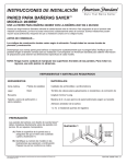
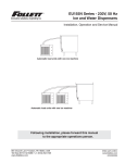
SERIES 4HOO AQUATUWER
Steel Crossflo~m Cooling Tower
The Marley Difference
Today's Aquatower may be the most space/energyefficient cooling tower available . Your needs have dictated
constant technological improvement. Thousands of Aquatower
users enjoy the benefits of eight major redesigns and dozens
of minor improvements in the past 40 years . For example, PVC
film-type fill enables the Aquatower to reject more heat per unit
size . We also put the air inlet louvers and drift eliminators right
on the fill sheets . This new arrangement saves you fan
horsepower by improving airflow through the tower.
The 4800 Aquatower is a maintenance delight! You'll
appreciate the way the Aquatower series simplifies
maintenance. No hidden spray systems, tiny nozzles, or
enclosed basins here! You can easily replace and align V-belts
from outside the tower. You won't have the chore and
expense that goes with high-horsepower, blower fan towers .
All primary components of the Aquatower are open to view .
You can easily remove any debris from the upper basin or
nozzles while the tower is in operation.
Heavy mill galvanizing on all steel components prevents
base metal corrosion. You won't have to worry about paint
The Aquatower has inspired many imitators . Only Marley
can offer you the original .
You'll enjoy single source responsibility and reliability
because we design and manufacture virtually all major cooling
tower components .
All Marley components are designed and selected to be a
part of an integrated system . For example, the spray pattern
from nozzles and the pressure drop through drift eliminators
both affect a fill's heat transfer capacity . So, we include that
impact in our thermal analysis .
Drift eliminators must be effective at the air velocities where
fill is most efficient . So, we've carefully designed both
components to work together efficiently.
How many other cooling tower companies can offer you
this assurance? They may use Brand "A" nozzles with Brand
"B" fill and Brand "C" drift eliminators . When they all come
together, the whole may be less than the sum of the parts.
Our total system approach assures that all the parts work
together to provide you the greatest total performance.
chips clogging your strainers and nozzles, because there is no
paint to flake off . Heavy galvanizing also protects much better
And because we design specifically for cooling towers, all
our components will provide many years of service with
Above all, the Aquatower is readily available . You won't
have to wait around-or accept second best-when you need
Every Aquatower cooling tower carries a full one-year
warranty . The Aquatower you buy from us will work on your
job or we'll make it right. Your warranty includes thermal
than paint alone.
a cooling tower. We maintain an impressive stock of
completed towers at our own plants . A growing number of
local distributors can draw from that stock.
Contact your local distributor or Marley representative .
They'll be glad to help you choose the proper model for your
needs. They can also help you with your layout and piping .
minimal maintenance.
performance and every component of the tower. The Marley
warranty is your assurance of performance-for a full year .
The Aquatower Advantage
Proven Performance. Don't rely
on outside agencies with limited
enforcement powers . Marley stands by our
responsibility for reliable thermal performance . We
designed it . We rate it . We guarantee it!
"
"
Induced-Draft Design . Save on fan power and avoid the
water leaks typical in forced-draft-pressurized-towers .
The fan will operate in a warm atmosphere even in winter,
so you'll never have to work on frozen mechanical equipment .
Crossflow Design . Save on pump power because you
only pay to move the water to the top of the tower. Gravity
does the rest . The mechanical equipment and water
distribution system are out where you can easily maintain
'fnem.
"
All-Season Reliability . Aquatowers perform as specified
in the heat of summer . They respond well to energy
management techniques in the spring and fall and, they
operate virtually ice-free in the dead of winter . Plus they
offer simple maintenance all year long . We guarantee it!
"
Proven Corrosion Protection . Thousands of users over
more than 40 years confirm the value of heavy galvanizing .
And Marley's G-235 is the most effective galvanizing used
in the industry .
PVC Film Fill with Integral Drift Eliminators and
Louvers. If you've ever had to replace deteriorated
eliminators or louvers, you'll appreciate this advantage .
Now those components are molded right in the PVC fill
sheets . Integral honeycomb louvers keep the circulating
water inside your tower-and off your roof! And the fill in
every Series 4800 Aquatower is approved by Factory
Mutual for use without sprinklers .
"
Select Your Aquatower From This Bulletin . The tables
on pages 7 through 9 should be adequate for almost all
your requirements . If available space is a problem, or if you
run into some unusual operating requirements, we'll be
glad to help .
"
Simple, Flexible Installation . Just mount the motor, belts
and belt guard, install the outlet connection that suits your
needs-both side suction and bottom outlet are provided,
complete with screens-and adjust the float valve. Attach
air-inlet screens on models 4851 and larger and your
Aquatower is ready for operation .
Caon
" Water Distribution System
" Fill/Louvers/Drift Eliminators
Warm water flows through external piping (not included
with the tower) into a splash box chamber at the top of the
Aquatower . A splash box prevents the incoming water from
spilling out of the basin and helps provide uniform water
distribution . Water then flows by gravity from the basin through
nozzles to the fill.
Fill sheets include integral louvers and drift eliminators,
designed to minimize resistance to airflow . This patented
arrangement prevents water from escaping the fill sheets,
assuring proper heat transfer throughout wide variations in
airflow . Users find this fill operates ice-free even in extremely
cold weather .
The thermoformed 15 mil (.015") thick PVC fill sheets
withstand hot water temperatures as high as 125°F. Fill sheets
are immune to biological and corrosive decay and their flame
spread rating is less than 25 per ASTM E-84 . Galvanized
structural tubes support and stabilize the fill. They also hold
the bottom of the fill sheets above the cold water basin floor to
simplify basin cleaning . Removable 1" x 1" mesh galvanized air
inlet screens keep larger airborne trash out of the collection
basin and fill area.
Eliminator air-seal removed showing distribution area above fill
Hot water distribution basin covers are provided as
standard equipment to keep the distribution basin free from
airborne debris and to reduce the likelihood of biological
growth.
All Aquatowers use Marley "Spiral Target" nozzles. These
inert polypropylene nozzles are evenly spaced thoughout the
distribution basin to assure uniform water distribution over all
portions of the fill . Their large openings resist clogging .
Nozzles are easy to remove and replace if you ever want to
change the design water flow rate.
MX75 fill
" Cold Water Collection Basin
The Aquatower's collection basin reduces operating weight,
simplifies basin cleaning, and assures proper outflow. Water
flows from the elevated area under the fill into the basin's rear
depressed section, where side suction piping connects. A
bottom outlet is also available for gravity flow applications .
Spiral-target distribution nozzle
Standard equipment on each tower basin includes : a
screened suction connection ; a threaded overflow connection ;
a threaded and plugged drain connection; and a floatoperated make-up valve. Models 4821 through 4872 also
include a bottom outlet conforming to 125# flange
specification . See page 13 for sizes. A blank cover plate is
provided to seal the outlet connection not used.
" Mechanical Equipment
Belt-driven propeller fans insure design airflow at minimum
horsepower . Fans on Model 4810 thru 4840 are supported by
grease lubricated pillow block bearings in a unitized assembly
with remote grease zerks . Models 4850 thru 4870 use an oillubricated tapered roller bearing assembly with remote oil
reservoir.
For ease of maintenance all drive components are
accessible from outside the tower. .
Fan drive motor showing adjustable base and belt guard
" Hoisting and Handling
Hoisting instructions on each tower explains how to use a
spreader-bar and slings beneath the cold water basin floor to
hoist the Aquatower . The tower's design also allows easy
handling with a forklift .
" Safety
Fan and fan guard . Guard is easily removed for access to fan and
drive belts
Fan drive motors are TEFC (may be TENV on model 4811)
designed specifically for cooling tower use . Horsepowers and
electrical characteristics appear in the table on page 10 . Other
types of motors are available . Typical options appear under
Optional Accessories on page 6.
Standard Aquatower safety features include fan guards and
belt guards . Fan guards consist of welded heavy gauge steel
wire hoops and spokes, hot dip galvanized after fabrication .
The galvanized steel belt guard encloses both belts and
pulleys . Guards are easily removed for servicing .
The fill sheets in every Series 4800 Aquatower are
approved by Factory Mutual for use without sprinklers with no
tower modifications .
" Construction and Finish
Aquatowers offer the corrosion protection of G-235
galvanized steel. Heavy mill galvanizing applied at the rate of
2 .35 ounces per square foot (2 .0 mils nominal thickness)
provides long term protection for the steel .
Optional
Accessories
Accessory
Description and Remarks
Accessory
Description and Remarks
Single Phase
Motors
In lieu of the 3-phase, 1 hp motors listed
on page 10, Models 4812 through 4831
are available with single-phase, 3/a hp,
115/230 volt, 1800 RPM, TENV motors.
Component
Basin Heaters
Special Motors
Two-speed (1800/900 RPM) motors are
readily available in 7 .5 and larger hp's, as
used on Models 4862, 4871 and 4872.
Although they are also available for the
smaller sizes, the effect upon lead time
can be significant-and the return on
investment is relatively small .
Standard heater components consist of 3
or 5 kW, 3 phase, 460 volt, shielded
immersion heater; solid state circuitry for
cut-off at low water level or high
temperature ; a control probe to monitor
basin water temperature and water level ;
and a magnetic contactor all housed in a
weatherproof enclosure . Components are
shipped separately for installation and
wiring by others . Designed to prevent
sump freezing during shutdown periods in
winter operation . Unnecessary if you use
an indoor tank. Special heater
characteristics result in extended lead
times .
Field Assembly
Where unique space restrictions or rigging
conditions demand, Aquatowers can be
shipped ready for field assembly by
others. Complete step-by-step assembly
instructions are provided .
Pre-assembled
Basin Heaters
Tank-type submersible heaters are
available for all models . No tower
modifications are necessary and heater
includes a 6-foot electrical cord with
grounded 3-prong plug for connection to
a standard 120V source . One or more 1 .5
kW elements provide protection at most
ambient conditions. The built-in
thermostat maintains 40°F water while the
built-in safety switch shuts off power if the
heater element is not submerged .
Stainless Steel
Construction
All Aquatower models are available with
stainless steel structure . Or you can
choose a galvanized tower with a
stainless steel cold water collection basin
(on all models except 4810) . You can
even choose a fan with stainless steel
blades . Your Marley sales representative
can help you choose the amount of
corrosion resistance necessary for your
installation .
Control System
Factory-installed control center in NEMA
3R enclosure mounted on tower casing .
Complete with thermostat controller for
single or two-speed motors to maintain
chosen cold water temperature .
Vertical
Discharge
Hood
This option is available on Models 4851
and larger . It provides vertical discharge
of the air leaving the tower . Hoods are
galvanized steel . They ship separately for
installation by others. A large access door
provides entry to the fan and mechanical
equipment .
Tower Selection Factors
How to select the appropriate Aquatower model :
1.
2.
3.
4.
5.
Subtract cold water temperature from hot water
temperature to determine "Cooling Range" .
Subtract design air wet-bulb temperature from cold water
temperature to determine "Approach to Wet-Bulb" .
Choose the table appropriate for your design air wet-bulb
temperature .
On the line for your calculated Range, proceed right to the
column for your calculated Approach and read Tower
Selection Factor . Interpolate mathematically, if
necessary .
Turn to Model Selection Chart on Page 9 .
Selection example : Select model to cool 325 GPM of water
from 101 ° to 85° at an entering air wet-bulb temperature
of 76° .
1.
2.
3.
4.
5.
Cooling Range is 16° (101 °- 85°) .
Approach to Wet-Bulb is 9° (85°- 76°) .
76°F Wet-Bulb tabulation is on Page 8 .
At a 16° range and 9° approach, Tower Selection
Factor is 4 .44 .
Proceed to Page 9 .
Note : All temperatures shown are degrees Fahrenheit .
65°F Wet-Bulb Selection Factors
Approach
Range
6
7
8
9
10
12
14
15
16
18
5
6
7
8
9
10
12
66°F Wet-Bulb Selection Factors
14
4 .10 4.69 5.21 5.67 6 .10 6.49 7.20 7.82
3 .68 4.25 4.75 5.21 5 .62 6.00 6.69 7.31
3 .33 3.88 4.37 4.82 5 .22 5.60 6.27 6.88
3 .04 3.57 4.05 4.48 4 .88 5.25 5.91 6.51
15
16
8.11 8 .38
7.59 7 .86
7.15 7 .42
6.78 7.04
2.79 3.31 3.77 4.20 4 .594 .955 .606 .186 .466 .7 1
2.37 2 .87 3.32 3.73 4.104 .455 .085 .655 .9 1 6.17
2.04 2 .52 2.96 3.35 3.71 4.05 4.67 5.22 5.48 5.73
1 .90 2 .37 2.80 3.19 3 .55 3.88 4.49 5.04 5.29 5.54
1 .77 2 .24 2.66 3.04 3.40 3.73 4.33 4.87 5.12 5.36
1 .55 2 .00 2.41 2.79 3.133 .454 .044 .574 .825 .06
Approach
Range
6
7
8
9
10
12
14
15
16
18
5
Range
6
7
8
9
10
12
14
15
16
18
5
6
7
8
9
10
12
Range
6
7
8
9
14
15
16
3 .61 4.16 4 .65 5.09 5 .50 5.87 6.55 7.15 7.43 7 .69
3.32 3.85 4.33 4.76 5 .16 5.52 6.19 6.78 7.06 7 .32
3.07 3 .59 4.05 4.48 4 .86 5.22 5.88 6.46 6.73 6.99
2.65 3 .15 3.604 .004 .384 .735 .365 .936 .196 .4 4
2.32 2 .80 3.24 3.63 3.99 4.33 4.95 5 .50 5.76 6.00
2 .18 2 .66 3.08 3.47 3.83 4 .16 4.77 5.32 5.57 5.81
2.06 2 .52 2.94 3.32 3.68 4 .01 4 .61 5.15 5.40 5.64
1 .83 2.29 2 .69 3.07 3.41 3 .73 4 .32 4.85 5.10 5 .33
10
12
14
15
16
18
6
7
8
9
10
12
9
10
12
14
15
16
7.91 8.20 8.47
7.40 7 .68 7.95
6.97 7.24 7.51
1 .87 2.33 2.75 3.14 3 .49 3.82 4.42 4 .96 5 .21 5.45
1 .642 .102 .51 2.883 .223 .554 .134 .664 .9 1 5.15
69°F Wet-Bulb Selection Factors
4.38 4 .96 5.48 5.94 6.37 6.76 7.47 8.09 8.38 8 .65
3.96 4.52 5 .035 .485 .896 .286 .977 .587 .868 .1 3
5
8
6 .606 .877 .13
2.88 3.40 3.87 4 .29 4.68 5.04 5.69 6 .28 6 .55 6.81
2 .462 .963 .41 3 .824 .194 .545 .185 .746 .0 1 6.26
2 .13 2.62 3.05 3.44 3 .81 4.15 4.76 5 .31 5 .57 5.82
1 .99 2.47 2.89 3.28 3 .64 3.97 4.58 5 .13 5 .38 5.63
Approach
Range
6
7
8
9
10
12
14
15
16
18
5
6
7
8
9
10
12
14
15
16
4.47 5.05 5.57 6.04 6.46 6.85 7 .56 8.18 8.47 8.75
4 .054 .625 .125 .575 .996 .377 .067 .677 .958 .2 2
3.70 4.25 4 .74 5 .18 5.59 5.96 6 .64
3.41 3 .95 4 .42 4.85 5.25 5.62 6.28
3.16 3.68 4 .15 4 .57 4.96 5.32 5.97
2.74 3.24 3.69 4 .10 4.47 4.82 5.45
7.24 7.52 7.79
6.87 7.15 7.41
6.55 6.82 7.08
6 .02
2.42 2.90 3.33 3 .72 4 .09 4.43 5.04 5 .59
2.28 2.75 3.18 3.56 3 .92 4.26 4 .86 5 .41
2.15 2.62 3.03 3.42 3 .77 4.10 4.70 5 .24
1 .93 2.38 2.79 3.16 3 .51 3.83 4.41 4.94
70°F Wet-Bulb Selection Factors
Approach
7
4.19 4.78 5.30 5 .76 6.19 6.58 7 .29
3.77 4.34 4.84 5 .30 5.71 6.09 6.79
3.43 3.98 4.46 4 .91 5.31 5.69 6.36
3.133 .674 .144 .584 .975 .346 .0 1
68°F Wet-Bulb Selection Factors
Approach
6
6.28 6.54
5.85 6.10
5.66 5.91
5.49 5.73
5 .19 5.43
72°F Wet-Bulb Selection Factors
14
15
16
4.56 5.15 5.666 .136 .556 .957 .658 .288 .568 .8 4
4.14 4.71 5.21 5.66 6.08 6.46 7.15 7 .76 8 .05 8 .32
3.80 4.35 4.83 5.28 5 .68 6.06 6.73 7.33 7 .61 7 .88
3 .51 4.04 4.52 4.95 5 .34 5.71 6.37 6.97 7 .24 7 .50
3 .25 3.77 4.24 4.66 5 .05 5.41 6.06 6.65 6 .92 7 .17
2 .84 3.34 3.79 4.19 4 .57 4.91 5.55 6.11 6.38 6 .63
2 .51 2 .99 3.423 .824 .184 .525 .135 .695 .946 .1 9
2 .37 2 .85 3.27 3.66 4.02 4 .35 4.96 5.50 5.76 6.00
2.25 2 .71 3.13 3.51 3.86 4.19 4.79 5.33 5.58 5.83
2.02 2 .48 2.88 3.26 3.60 3 .92 4.51 5.04 5.28 5.52
Approach
Range
6
7
8
9
10
12
14
15
16
18
5
6
7
8
9
10
12
14
15
16
4 .75 5 .33 5.85 6.31 6.74 7 .13 7 .84 8.46 8.75
4.33 4 .90 5.40 5.85 6.26 6 .65 7 .34 7.95 8.23 8 .50
3.99 4.53 5 .02 5.46 5.87 6.24 6 .92 7.52 7.80 8.06
3.694 .234 .705 .135 .535 .906 .567 .157 .43 7.69
3.44 3.96 4 .43 4.85 5.24 5.60 6.25 6.83 7.10 7.36
3.03 3.53 3 .97 4.38 4.76 5.10 5.74 6 .30 6.56 6.81
2. 70 3.18 3 . 61 4. 01 4. 37 4. 71 5. 32 5 . 87 6.13 6.38
2.563 .043 .463 .854 .2 1 4.545 .145 .695 .9 4 6.19
2.44 2 .90 3.32 3.70 4 .05 4.38 4.98 5 .52 5.77 6.01
2.22 2.67 3.07 3.45 3 .79 4.11 4.70 5.22 5 .47 5.71
Tower Selection Factors
75°F Wet-Bulb Selection Factors
73°F Wet-Bulb Selection Factors
Approach
Range
6
7
8
9
10
12
14
15
16
18
5
6
7
8
9
10
12
14
15
4.84
4.43
4.08
3.79
3 .54
3.13
2.80
2.66
2 .53
2 .31
5.42
4.99
4.63
4.32
4 .06
3 .62
3 .28
3 .13
3.00
2.76
5 .94
5 .49
5 .12
4.80
4.52
4.07
3.71
3.56
3.42
3 .17
6.41
5.94
5.56
5.23
4.94
4.48
4.10
3.94
3.80
3.54
6.83
6.36
5.96
5.62
5.33
4.85
4.47
4 .30
4 .15
3 .88
7.22
6.74
6 .34
5 .99
5 .69
5 .20
4.80
4.63
4.48
4.21
7.93
7.43
7 .01
6 .65
6 .34
5 .83
5 .42
5 .24
5.08
4.79
8 .55
8 .04
7 .61
7.25
6.93
6.39
5.97
5.78
5.61
5.32
8.84
8.32
7.89
7.52
7.20
6.66
6.22
6.04
5.87
5.56
16
Approach
Range
8.59
8.16
7.78
7 .45
6 .91
6 .47
6 .28
6 .11
5.80
6
7
8
9
10
12
14
15
16
18
5
6
7
8
9
10
12
14
15
16
5.03
4.62
4.27
3.98
3.73
3.32
2.99
2.85
2.73
2.51
5 .61
5.18
4.82
4.51
4.25
3.82
3.47
3.32
3 .19
2.96
6 .13
5 .68
5.30
4.99
4.71
4.26
3 .90
3 .75
3 .61
3 .36
6.59
6.13
5.75
5.42
5.13
4.67
4.29
4 .13
3 .99
3 .73
7.02
6 .54
6 .15
5 .81
5 .52
5 .04
4.66
4.49
4.34
4.08
7 .41
6.93
6.52
6.18
5.88
5 .39
4.99
4.82
4.67
4.40
8.11
7.62
7.20
6.84
6.53
6.02
5.61
5.43
5.27
4.98
8.74
8.20
7.80
7.43
7.11
6.58
6 .16
5 .97
5 .80
5 .51
8 .51
8.08
7 .71
7 .38
6 .84
6 .41
6 .22
6.05
5 .75
8 .78
8 .34
7.97
7.64
7.10
6.66
6.47
6.29
5.99
77°F Wet-Bulb Selection Factors
76°F Wet-Bulb Selection Factors
Approach
Range
6
7
8
9
10
12
14
15
16
18
5
6
7
8
9
10
12
14
15
16
5.13 5.71 6 .22 6 .69 7.11 7.50 8 .21 8 .83 4.71 5.27 5 .77 6.23 6.64 7.02 7 .71 8.32 8.60 8.87
4.37 4 .91 5 .40 5.84 6 .24 6.62 7 .29 7.89 8.17 8.44
4.08 4 .61 5.08 5 .51 5.91 6.27 6 .94 7.53 7.80 8.06
3.83 4 .34 4.81 5.23 5.62 5 .98 6 .63 7.21 7.48 7.73
3.423 .91 4.364 .765 .145 .486 .1 1 6.686 .947 .19
3 .09 3.57 4.00 4.39 4 .75 5.09 5.70 6.25 6 .51 6 .75
2 .95 3.42 3.84 4.23 4 .59 4.92 5.52 6.07 6.32 6 .56
2 .83 3.29 3.70 4.08 4 .44 4.76 5.36 5.90 6.15 6 .39
2 .603 .053 .463 .834 .174 .495 .075 .605 .856 .0 8
Approach
Range
6
7
8
9
10
12
14
15
16
18
5
6
7
8
9
10
12
14
15
16
5.22
4 .81
4 .46
4 .17
3 .92
3.51
3.19
3.05
2.92
2.70
5 .80
5.37
5 .01
4.70
4.44
4.01
3.67
3.52
3.38
3 .15
6.32
5.87
5.49
5.18
4.90
4.45
4.09
3.94
3 .80
3.56
6.78
6.32
5.93
5.61
5.32
4.86
4 .49
4 .33
4 .18
3 .93
7 .21
6.73
6 .34
6 .00
5 .71
5 .23
4.85
4.68
4.53
4.27
7.60
7 .11
6.71
6.37
6.07
5.58
5.18
5.01
4.86
4.59
8 .30
7.80
7.39
7.03
6 .72
6 .21
5.79
5.62
5 .46
5 .17
8.92
8.41
7.99
7.62
7.30
6.77
6 .34
6 .16
5 .99
5.69
8.70
8.26
7.89
7 .57
7 .03
6 .60
6 .41
6.24
5 .94
8 .97
8 .53
8 .15
7.83
7.28
6.84
6.65
6.48
6.17
14
15
16
79°F Wet-Bulb Selection Factors
78°F Wet-Bulb Selection Factors
Approach
Range
6
7
8
9
10
12
14
15
16
18
5
6
7
8
9
10
12
14
15
5.32 5.90 6 .41 6.88 7.30 7.69 8 .39 4.90 5 .46 5.96 6.41 6.83 7.21 7 .90 8.51 8.79
4.56 5 .10 5.59 6.03 6.43 6.81 7 .48 8.08 8.36
4.27 4 .80 5.27 5.70 6.10 6 .46 7 .12 7.71 7.99
4.02 4 .54 5.00 5 .42 5 .81 6 .16 6.81 7.39 7.66
3.61 4.11 4.55 4.95 5 .33 5 .67 6.30 6.86 7.13
3.293 .764 .194 .584 .945 .285 .896 .446 .6 9
3 .153 .624 .044 .424 .785 .1 1 5.71 6.256 .51
3 .02 3.48 3.90 4.28 4.63 4.95 5.55 6.09 6 .34
2 .80 3.25 3.65 4 .02 4.36 4.68 5.26 5.79 6 .03
16
Approach
Range
6
8.62
8.25
7 .92
7 .38
6 .94
6 .75
6.58
6.27
7
8
9
10
12
14
15
16
18
5
6
7
8
5 .41
5 .00
4 .66
4.37
4.12
3 .71
3.38
3.24
3.12
2.90
5.99
5.56
5.20
4.90
4.63
4.20
3.86
3.71
3 .58
3 .35
6.51
6.06
5.69
5.37
5.10
4.65
4.29
4.13
3 .99
3 .75
6.97
6.51
6.13
5.80
5 . 52
5 .05
4 .68
4 .52
4.37
4.12
Range
6
7
8
9
10
12
14
15
16
18
10
12
7 .39 7 .78 8.49 6 .92 7 .30 7.99 8.60 8 .88 6 .53 6.90 7.57 8.17 8 .45 8.72
6 .196 .567 .227 .8 1 8 .088 .34
5.90 6.26 6.91 7.49 7 .76 8.01
5.42 5.77 6.40 6.96 7 .22 7 .47
5.04 5.37 5 .98 6.53 6.79 7.03
4.87 5.20 5 .81 6 .35 6.60 6.84
4.72 5 .05 5 .65 6.18 6.43 6.67
4.464 .785 .365 .886 .136 .3 6
82°F Wet-Bulb Selection Factors
80°F Wet-Bulb Selection Factors
Approach
9
5
6
7
8
9
10
12
14
15
5.51
5.09
4.75
4 .46
4 .21
3 .81
3.48
3.34
3.22
3 .00
6 .09
5 .66
5.30
4.99
4.73
4.30
3.96
3.81
3.68
3.44
6 .60
6 .15
5.78
5.47
5.19
4.74
4.38
4.23
4.09
3 .85
7.06
6.60
6.22
5.89
5 .61
5 .15
4 .77
4.62
4.47
4.21
7.49
7.02
6.62
6 .29
6.00
5.52
5.13
4.97
4.82
4.56
7 .88
7 .40
7 .00
6.65
6.36
5.86
5 .47
5.30
5.15
4.87
8 .58
8.09
7.67
7.31
7.00
6.49
6 .08
5.90
5 .74
5 .45
8.70
8.27
7.90
7.58
7.05
6.63
6 .44
6 .27
5 .98
8.98
8.54
8.17
7 .85
7 .31
6 .88
6.69
6.52
6 .22
16
Approach
Range
8 .81
8 .43
8.11
7.56
7.13
6.94
6.76
6.46
6
7
8
9
10
12
14
15
16
18
5
6
7
8
5.70 6.28 6.79 7 .25
5.29 5.85 6.34 6 .79
4.95 5.49 5.97 6 .41
4.66 5.19 5 .66 6 .09
4.41 4.92 5 .39 5.80
4.00 4.49 4 .94 5 .34
3.684 .154 .584 .9 7
3 .54 4.01 4.43 4.81
3 .41 3.87 4.29 4.66
3 .19 3.64 4.04 4.41
9
10
12
14
15
16
7.68 8.07 8.77
7.21 7.59 8.27 8.88 6.81 7.19 7 .86 8 .46 8.73 9.00
6 .48 6.84 7 .50 8 .09 8.36 8.62
6 .196 .557 .197 .778 .048 .30
5.71 6.05 6.68 7 .24 7.50 7.75
5.33 5 .66 6.27 6.82 7.07 7.31
5.16 5 .49 6.09 6 .63 6.88 7 .12
5.01 5 .34 5.93 6.46 6 .71 6.95
4.75 5 .07 5.64 6.17 6 .41 6.64
Aquatower Model Selection
The following chart defines the maximum cooling capacity
Selection Example: Tower Selection Factor is 4 .44.
Design GPM is 325.
in GPM for each Aquatower model at the Tower Selection
Factor defining your design conditions of entering hot water,
leaving cold water, and entering air wet-bulb temperatures .
1.
the design requirement at your calculated Tower Selection
Using the 4.0 column (smaller than 4.44) the selection
would be a Model 4871 .
2.
However, interpolating for a 4.44 factor between the 4.0
column (295 GPM) and the 4.5 column (333 GPM)
reveals that the Model 4862 is capable of cooling 328.4
GPM at the design temperatures .
Select the model whose GPM capacity equals or exceeds
Factor .
1.
"Safe" selections result from using the Tower Selection
Factor column equal to or smaller than the factor calculated .
2.
"Accurate" selections result from mathematical interpolation, if necessary.
Note :
If GPM exceeds maximum model capacity, divide
into two or more towers .
Model Selection Chart
Model Capacity In GPM of Clear Water
Tower Selection Factor
Model
1 .5
~ 2.0
2.5
3.0
3.5
4.0
4.5
5.0
5.5
6.0
6.5
7.0
7.5
8.0
8.5
9.0
4811
13
19
25
14
21
29
16
24
32
18
27
37
21
31
42
23
35
47
27
40
53
30
45
60
34
51
68
38
57
76
43
64
86
49
73
97
55
82
110
62
90~
124
70
90~
140
80
90`
150'
4851
31
38
50
63
75
99
4852
111
36
43
57
71
85
111
125
139
160
182
234
256
40
49
65
81
97
125
141
157
181
205
264
289
46
56
73
92
110
141
159
177
204
232
297
326
52
63
83
104
124
159
179
200
230
261
335
367
59
71
94
117
141
178
202
225
259
295
378
414
66
80
106
133
159
200
227
253
292
333
426
466
75
90
120
150
180
225
255
285
330
375
480
525
85
101
135
169
203
252
286
320
373
423
541
591
96
113
152
191
229
282
320
359
421
476
608
666
108
127
172
215
258
316
358
402
475
537
684
749
122
142
193
242
291
352
400
450
535
604
768
842
138
159
217
272
328
392
446
503
602
679
861
900`
150
178
225
307
350
435
495
561
675
750
900"
900
150
199
225"
346
350
482
549
570
750'
750'
900"
900
150"
223
225
350
350
533
570
570
750
750
900
900`
4812
4821
4822
4831
4832
4841
4842
4853
4861
4862
4871
4872
124
142
161
207
227
Maximum design water flow rate
Schematic
L
TOWER~ INLET
VERTICAL
DISCHARGE
(OPTION)
:'~: :a:::'~C:=
"""""..:"""Y
N
""
"""""""""""
.....a :::::""~
nuo
u"""u
"""""~""
uuuuuuuy
""u""" uu"""
H
"""Y
"""""N
"
"Y
""""""""""
N """p""" N :
"""u"""
""
"~""°:uu":::::
.uuuuomu
": : : :fin:::u :~
0
TOWER OUTLET
51DE ELEVATION
AIiZ INLET ELEVATION
Tower Nominal
Model Tons 1
4811
10
4812
15
4821
20
4822
25
4831
30
4832
40
4841
50
4842
60
4851
75
4852
85
4853
95
4861
110
4862
4871
4872
175
1.
2.
3.
4.
DIMENSIONS
L
W
H
p
B
C2
2'-11 '/z"
4'-2 ~/s°
5'-3 3/a°
1'_3'3/is°
402mm
6'/s'
175mm
610mm
3'-11 Yz°
5'-0 3/a"
T_4 ,h%
1,-5
g ,/z
4, -0 902mm
1206mm
3'_11 ~/z°
1206mm
5'-11 '/z"
1292mm
1534mm
1610mm
2248mm
5'-0 3/a°
T-4 ~/z°
1543mm
2248mm
432mm
1'-5"
432mm
241mm
1219mm
9'h°
g ,/z 5,_0
5'-1"
T_q'/z°
2248mm
432mm
241 mm
1524mm
5'-11 ~/z°
6'-5 5/a'
1972mm
g'_0 2743mm
2'_0°
610mm
11 ~/z°
292mm
6'_0 1829mm
6'-5 3/a"
1975mm
9'_0 2743mm
2'_0`
610mm
11 '/z'
T_0
125
T_11 ~h'
2426mm
160
9'-11 ~/z°
6'-6~/s°
9'-8'/a"
1'-11 3hs"
3035mm
1984mm
2953mm
~
ocLe
1219mm
1549mm
589mm
~
4'-0"
241mm
1816mm
1816mm
1'_5 2'_0"
292mm
11 ~/z°
292mm
Nominal tons are based upon 95°F HW, 85°F CW, 78°F WB, and
3 GPM/Ton.
Minimum clearance for adequate air supply . Consult Marley or
your local distributor if this clearance is impractical for your job .
Vertical discharge hoods are not available on these models .
Motors less than 1 hp are 115/230 volt, single-phase TENV . 1 hp
through 10 hp motors are 230/460 volt, 3-phase TEFC . See
page 6 for optional motor sizes on Models 4812 through 4831 .
5.
6.
7.
8.
9.
10
i
S
;~ 4'-3 ~/a"
1318mm
203mm
8"
203mm
8
Inlet
Outlet s
/3
2
2 F
4"
4" M
g"
6 MC
~
1
6, 5
1
1956mm
1
1956mm
6''S°
1
2
203mm
1956mm
6,-5
2
3251mm
g ya%
235mm
T_10 5/e'
2
3
10 ,_8
g ,/a%
T_10 5/e°
2403mm
5
7,/z
9'/a"
8'-6 3/a°
7'/z
~
10,-8
2403mm
3
5
2134mm
3251mm
9'_0"
10'_11 "hs"
2743mm
E
D
3345mm
235mm
235mm
2610mm
Piping
Connections
Motor
hp
10
Motor and belt guard ship unlnstalled . Installation by others .
Outlet sizes shown are side outlets . All models except 4811
and 4812 have connections for both side and bottom outlet .
Install the desired connection and seal the unused opening with
the coverplate provided . Pump suction should use side outlet .
See page 13 for size and flow capacities of bottom outlets .
Overflow is a 2" F connecton located in side of collection basin.
Drain is a 2" F connection located in collection basin floor.
Makeup valve connection is 3/4" M located in tower side .
Supporting
Steel
L
r'
F
~
ANCHOR
ANCHOR I
BOLT
BOLT
TOWER
I l,
COLLECTION BASIN
I
W G
I
,~ DIAMETER HOLES
o
zo
¢m
~
I
I I
I
I~IB
I
I
AIR INLET FACE
SUPPORTING STEEL PLAN
TOWER
COLLECTION
BASIN
SUPPORTING STEEL PLAN
Oi'TION ONE
TOWER
COLLECTION
BASIN
I` NORMAL
4821-4822
4831-4832
4841-4842
4851-4853
4861-4862
4871-4872
VIEW B
DIMENSIONS
L
W
F
G
H
2 -11 Yz°
902mm
3'-4"
1016mm
4'-1 3/a°
1264mm
4'-1 3/°~
1264mm
4'-1 3/a°
1264mm
5'-6"
1676mm
S'-6"
1676mm
2'-9'/z'
851mm
3'-9'/z'
1156mm
3'-9 ~/z"
1156mm
5'-9'/z°
1765mm
3'-0"
915mm
3'-6"
1067mm
3'-6"
1067mm
51mm
3'/a°
98mm
3 ~/e"
98mm
3'_6"
1067mm
3'/s°
98mm
5'-9'/z"
1765mm
T-9 Yz°
2375mm
5'-0"
1524mm
3"
76mm
5'-0"
1524mm
3"
76mm
5'_6"
1676mm
9'_9'/z°
2985mm
5'_0"
1524mm
3°
76mm
,
3-11 Yz °
1206mm
3-11 ~/z'
1206mm
5'-11 ~/z"
1816mm
5-11 Yz°
1816mm
7-11 '/z'
2426mm
9~ - 11 '/z"
3035mm
5'-6"
5'-9'/z`
5'-0"
3"
4861-4862
T-11 ~/z"
5'-6"
T-9 ~/z°
5'-0"
3"
4871-4872
9'-11 Yz°
5'-6"
9'-9 'h°
5'-0"
3"
3.
ib
16mm
Ib
Maximum
Operating
Load at
Anchor
Ib
Wind Loads Ib
Max. Vertical
Reaction
at Anchor
Max. Horizontal
Reaction
at Anchor
435
740
185
180
115
740
1340
335
350
205
755
1360
340
355
210
980
1940
485
525
285
1410
2960
740
555
355
1805
3900
975
745
470
2185
4840
1210
1095
640
Yz°
13mm
5/e~
Maximum
Operating
Weight
Models with Vertical Discharge Hood Option
5'-11 Yz'
2.
J
Shipping
Weight
2"
4851-4853
1.
GAUGE
SUPPORT
(BY OTHERS)
SECTION A
4811-4812
MIN. BEARING WIDTH
AT EACH ANCHOR BOLT
NORMAL
GAUGE
SUPPORT
(BY OTHERS)
Tower
Model
OPTION TWO
5/a°
Use this bulletin for preliminary layouts only. Obtain current
drawings from your Marley sales representative or your local
distributor.
Purchaser to provide tower supports complete with holes and
bolts for anchorage. All supports must be framed flush and level
at top . Maximum deflection to be 1/360th of span, not to exceed
Yz' (13mm) .
Maximum weight occurs with basin full to overflow level. Actual
1810
3360
2180
840
700
515
4280
1070
745
515
2685
5340
1335
1095
640
4.
5.
operating weight varies with GPM and piping scheme, but will
always be less than shown here .
Wind loads are based on 30 psf and are additive to operating
loads. Reactions due to wind loads exceed those resulting from
seismic loads based on UBC, Zone 4.
Consult your Marley application engineer if tower is to be
supported directly on vibration isolators. Basin modifications
may be necessary .
Freeze Prevention
When the ambient air temperature falls below 32°F, the
" Indoor Tank Method
water in a cooling tower can freeze . Marley Technical Report
#H-003 "Operating Cooling Towers in Freezing Weather"
describes how to prevent freezing during operation . Ask your
Marley sales representative for a copy .
Water collects in the cold water basin during shutdowns,
In this type of system, water flows from an indoor tank,
through the load system, and back to the tower, where it is
cooled . The cooled water flows by gravity from the tower to
the tank located in a heated space . At shutdown, all exposed
water drains into the tank, where it is safe from freezing .
and may freeze solid . You can prevent freezing by adding heat
to the water left in the tower . Or, you can drain the tower and
all exposed piping at shutdown .
The table on page 13 lists typical drain-down capacities for
all Aquatower models . Although Marley does not produce
tanks, many of our representatives offer tanks supplied by
reputable manufacturers .
" Electric Basin Heaters
Choose from two types of automatic basin heater systems,
based on your site conditions and preferences .
You may choose a heater system consisting of these
components (shipped separately for installation by others) :
Stainless steel electric immersion heater element(s) .
Threaded couplings are provided for installation .
NEMA 4 enclosure containing these components :
-Magnetic contactor to energize heater .
-Transformer to convert power supply to 24 volts for
control circuit .
The amount of water needed to successfully operate the
system depends on the tower size, GPM and the volume of
water contained in the piping system to and from the tower .
You must select a tank large Pnough to contain those
combined volumes-plus a level sufficient to maintain a
flooded suction on your pump . Control makeup water
according to the level where the tank stabilizes during
operation .
You should always use a bottom outlet for this type of
piping system . The following table lists the flow capacities for
bottom outlets .
-Solid state circuit board for heater control and low-water
cutoff .
Enclosure may be mounted on the side of the tower .
+10° F Ambient
Model
Control probe to monitor water temperature and water
level . Threaded couplings are provided for installation .
Or you may prefer a pre-assembled submersible tank-type
heater which requires no tower modification and can plug into
a standard grounded 3-prong 120V outlet .
The Incoloy heater element was chosen for its long life in
Req'd
kW
Tank
Heater
Component
Heater
Req'd
kW
Tank
Heater
Component
Heater
4811
4812
0 .56
1 .5 kW
3 kW
0.89
1 .5 kW
3 kW
4821
4822
O.g3
1 .5 kW
3 kW
1 .47
1 .5 kW
3 kW
4831
4832
0.93
1 .5 kW
3 kW
1 .47
1 .5 kW
3 kW
1'39
1 .5 kW
3 kW
2.19
1
@
3 kW
1 .91
1
3 kW
3.00
1
2'53
1
3 kW
4.00
1 5@w
3.15
1
4.5 kW
4.97
submerged environments . A built-in thermostat senses water
4842
temperature and controls the supply of electricity to maintain
4851
4852
4853
proper water temperature . A built-in safety switch cuts off
power whenever the element is exposed to air . The element
mounts in the tower basin on a stainless steel plate .
4862
Any exposed piping that is still filled with water at shutdown
4872
-including the makeup water line-should be electrically
traced and insulated (by others) .
1.
2.
3.
4.
5.
12
-10° F Ambient
b@W
5kW
6~kW
6 W
b~kW
@
1 .5 W
3 kW
4.5 kW
6 kW
Required kW is the amount of heat needed to maintain +40 - F
basin water temperature at the indicated ambient air
temperature .
Tank heaters shown are 120 volts, single-phase .
Component heaters shown are 480 volts, three-phase .
Options or special heater selections may add several weeks to
delivery .
Heaters do not operate continuously . Heaters cycle on and off
automatically as basin water temperature dictates .
Contact your Marley sales representative for selections
appropriate for other ambient conditions than those shown
here .
Field
Assembly
" Field Assembly
Model
4811
4812
Range of Tower
Design GPM
Maximum Drain-Down
gallons
12 - 26
25
46 - 65
28
27 - 45
4841
4842
4861
4862
18 - 36
43
37 - 63
46
120 - 225
57
28 - 56
67
64 - 119
The following table shows the sizes and weights of the
largest Aquatower components for each model . You can use
this information to plan your rigging and transportation needs .
51
57 - 99
Unassembled tower shipment may add 3 to 5 weeks to
normal lead times . Your Marley sales representative will be
glad to help you plan for your unique needs .
72
100 -187
79
Note :
89
55-113
114 - 200
the US by sea or air freight .
142
201 - 375
158
376 - 625
177
75 - 155
177
156 - 270
191
271 - 510
Model
216
4811
4812
240
95 - 195
230
196 - 285
244
286 - 490
268
491 - 900
306
4821
4822
4831
4832
Volumes shown are maximums for the GPM ranges indicated .
Actual volumes will usually be less . Contact your local Marley sales
representative for more specific information .
4841
4842
Maximum Bottom Outlet GPM
Tower Model
1.
2.
For economical transportation, Aquatowers are
normally packaged unassembled when shipped from
131
511 - 50
4871
4872
assembly instructions .
29
188 - 350
4851
4852
4853
your Aquatower will be shipped unassembled with complete
27
66 - 90
4821
4822
4831
4832
If you choose to assemble your Aquatower at the job site,
Outlet Diameter
4851
4852
4853
6"
4821-4822-4831-4832
225
4841-4842
270
_
4851-4852-4853
550
4861-4862
550
4871-4872
550
Component
Size in
Weight Ib
Collection Basin End
12 x 13 x 36
15
Collection Basin Floor
3 x 30 x 32
23
Front Panel
2 x 36 x 44
21
Casing
2 x 40 x 52
43
Distribution Basin
8 x 16 x 32
18
Collection Basin End
14 x 16 x 48
24
Collection Basin Floor
3 x 36 x 44
37
Casing
2 x 26 x 63
Front Panel
2 x 48 x 68
Distribution Basin
Maximum GPM applies to both pump and gravity flow piping
systems . The outlet piping on gravity flow systems must have
sufficient vertical drop to overcome all other head losses in
the system .
Bottom outlet is not available on Models 4811 and 4812 .
4871
4872
24
Collection Basin End
14 x 16 x 72
37
Collection Basin Floor
3 x 36 x 68
56
Front Panel
2 x 37 x 72
35
Casing
2 x 26 x 63
34
Distribution Basin
8 x 16 x 68
37
Collection Basin End
18 x 18 x 72
47
Collection Basin Floor
4 x 34 x 68
56
Front Panel
2 x 44 x 72
41
Casing
2 x 40 x 76
63
Distribution Basin
8 x 28 x 68
52
Discharge Hood Floor
9 x 45 x 68
Collection Basin End
18 x 18 x 96
63
Collection Basin Floor
4 x 34 x 92
75
Front Panel
2 x 44 x 96
56
Casing
2 x 40 x 76
63
Distribution Basin
8 x 28 x 92
70
Discharge Hood Side
2 x 41 x 77
37
Discharge Hood Floor
9 x 45 x 63
41
Collection Basin End
18 x 18 x 120
79
Collection Basin Floor
4 x 34 x 116
95
Casing
2 x 40 x 84
69
Distribution Basin
8 x 28 x 116
88
Discharge Hood Side
2 x 45 x 77
38
2 x 41 x 77
Front Panel
Discharge Hood Floor
13
34
8 x 16 x 44
Discharge Hood Side
4861
4862
52
37
46
2 x 46 x 120
I
9 x 45 x 77
71
I
54
Application
You can use the Series 4800 Aquatower in normal
applications requiring cold water for the dissipation of heat .
Some common applications include:
Condenser water service for air conditioning and refrigeration systems.
Jacket water cooling for engines and air compressors.
"
Welder cooling.
"
Plastic industry processes.
"
Dairy, citrus, and other food industry processing where
barometric condensers are not in use.
The table below will help you determine the heat load-and,
therefore, the cooling tower capacity-you'll need for your
duty . If you don't find your application below, or if you need
Chemical and industrial processes .
more specific help, contact your Marley sales representative .
Batch cooling .
" Typical Equipment Heat Loads
Type of Equipment
Cooling
Range
°F
Btu
GPM
Air Conditioning or Refrigeration
Electric motor driven compressor
Steam turbine driven compressor
Absorption machine-Single Stage (steam-fired)
Absorption machine-Two Stage (gas-fired)
per Ton
15,000/hr
30,000/hr
30,000/hr
22,500/hr
per Ton
1 .5 - 3
2-3
3.33
3 - 4 .5
20 - 10
30 - 20
18
15 - 10
Diesel Engine Jacket Water & Lube Oil
Four-cycle, supercharged
Four-cycle, non-supercharged
per BHP
2600/hr
3000/hr
per BHP
.26
.30
20
20
Natural Gas Engine Jacket Water & Lube Oil
Four-cycle engine
Two-cycle engine
per BHP
4500/hr
4000/hr
per BHP
.45
.40
20
20
Electric Motor Driven Air Compressors
Reciprocating & screw type (200 hp and less)
Centrifugal (250 hp and above)
per BHP
2800/hr
2800/hr
per BHP
.28
.28
20
20
Reciprocating & screw type (200 hp and less)
Centrifugal (250 hp and above)
per CFM
622/hr
560/hr
per CFM
.065
.055
20
20
Plastic Injection Machines
per oz capacity
125/min
1 .5
10
Hydraulic Oil Cooling
2545/hr/BHP
.51/BHP
10
Welding Tip Cooling
84/min (avg)
1 .0
10
Note: When possible, determine actual heat load and water quantity to be circulated, and
apply in the following formula :
Cooling Range =
Heat Load (Btu/min)
GPM x 8.33
Where :
8 .33 = Pounds per gallon of water
Cooling Range = Difference between hot water entering tower and cold
water leaving tower (°F)
" Applications Requiring System Modifications or
Alternative Cooling Tower Selections
Certain types of applications are incompatible with any
galvanized steel cooling tower with PVC film-type fill-whether
Series 4800 Aquatower or a competitive tower of similar
manufacture . Some of these applications, which call for either
system modifications or an alternative tower design are:
Water temperatures exceeding 125°F-potential
corrosion of galvanized surfaces is accelerated and service
life of PVC may be reduced . Use either a cold water
bypass or an intermediate heat exchanger between the
load and the tower to limit hot water temperature .
Highly corrosive environment-typified by proximity to
bodies of salt water, presence of corrosive vapors (as in a
chemical or steel plant) or the presence of unusually dense
air pollution in the form of SOx, hydrogen sulfide (H2 S) or
potentially corrosive particulates . While a galvanized tower
may function effectively in these types of environments, an
alternative selection constructed of corrosion-resistant
materials offers even longer service life .
Ethylene glycol content-can plug fill passages as slime
and algae accumulate to feed on the available organic
materials . An intermediate heat exchanger or an alternative
splash-fill Marley tower selection will solve the problem .
" Alternate Material Selections
In addition to galvanized steel, Marley offers stainless steel
or fiberglass to meet the special demands of specific
applications .
Stainless steel construction-you may choose stainless
for all or part of your Series 4800 Aquatower . See page 6
for more information .
Series 3800 Aquatower-fiberglass construction assures
long service life in virtually any environment . One-year full
product warranty on all components. Efficient PVC filmtype fill .
For additional information on these products, and for
application assistance with whichever Marley product you
choose, consult your local Marley sales representative .
If we can help in any way, feel free to call us. To find the
Marley representative nearest you call 913 664 7400 or check
the Internet at www .marleyct .com .
® Water Treatment
To control the buildup of dissolved solids resulting from
water evaporation, as well as airborne impurities and biological
contaminants including Legionella, an effective consistent
water treatment program is required . Simple blowdown may
be adequate to control corrosion and scale, but biological
contamination can only be controlled with biocides.
Most systems can be successfully treated with a
MARLEYOZONET~' System . Not only is MARLEYOZONE an
excellent biocide, it can also be utilized to control corrosion
and scale. This usually removes the requirement for other
chemical feed systems . In many installations there is the
potential for significant water savings . For complete
information, contact your local Marley sales representative .
An acceptable water treatment program must be
compatible with the variety of materials incorporated in a
cooling tower-ideally the pH of the circulating water should
fall between 6.5 and 8.0 . Batch feeding of chemicals directly
into the cooling tower is not a good practice since localized
damage to the tower is possible . Specific startup instructions
and additional water quality recommendations can be found in
the Aquatower User Manual which accompanies the tower
and also is available from your local Marley sales
representative . For complete water treatment
recommendations, consult a competent, qualified water
treatment supplier.
Specifications
Base : Furnish and install an induced-draft, crossflow, factoryassembled, steel cooling tower of
cell(s), as shown on
plans . Tower shall be similar and equal in all respects to
Marley Series 4800 Aquatower, Model _______ . Tower
must be warranted by the manufacturer for one year from
date of shipment .
Performance : Tower shall cool
GPM of water from
°F
to
°F at a design entering air wet-bulb temperature of
°F .
Construction : Structural components of the tower, including
the cold water basin, framework, mechanical equipment
supports, casing, hot water basin, and fan cylinder shall be
fabricated of heavy-gauge steel, protected against
corrosion by G-235 galvanizing . All components subjected
to factory welding shall be hot dip galvanized after
completion of fabrication to a zinc thickness equivalent of
G-235 . Cold galvanizing is not acceptable .
Motor : Motors) shall be
hp, Totally Enclosed, specially
insulated for cooling tower duty . Speed and electrical
characteristics shall be 1800 (or 1800/900) RPM, single
winding, - phase,
hertz,
volts . The motor
must be located out of the saturated discharge air stream .
Mechanical Equipment : Fans) shall be fixed-pitch propeller
type . Fan shall be driven through V-belts) with a minimum
service factor of 1 .50 based on full motor hp . The fan and fan
pulley will be mounted on a bearing assembly with stainless
steel shaft .
u
Marley Cooling Tower
A United Dominion Company
The Marley Cooling Tower Company
7401 W 129 Street " Overland Park, KS 66213 " 913 .664 .7400
email : infoCmarleyct .co m " www .marleyct .co m
In the interest of technological progress, all products are
subject to design and/or material change without notice .
©2000 Marley Cooling Tower
Printed in USA
AQ-OOA
Fill, Louvers and Drift Eliminator: Fill shall be film-type,
thermoformed PVC, with louvers and drift eliminator formed
as part of each fill sheet . Fill shall be suspended from hot dip
galvanized structural tubing supported from the upper
tower structure, and shall be elevated above the floor of the
cold water basin to facilitate cleaning . Air inlet faces of the
tower shall be free of water splash-out . Guaranteed drift
losses shall not exceed 0 .005% of the design GPM . Fill/
louver/eliminator system must be approved by Factory
Mutual Research Corporation for use in factory-assembled
cooling towers ; and must be listed in the Factory Mutual
Approval guide .
Hot Water Distribution System : An open basin above the fill
bank shall receive hot water piped to each cell of the tower .
The basins shall be equipped with removable covers to
keep out debris . This basin shall be installed and sealed at
the factory . Water shall enter the basin through a removable
wave-suppressor splash box . The basin shall be no less
than 6 3/s' deep to provide adequate freeboard against
overflow and splash-out . Removable and replaceable
polypropylene nozzles installed in the floor of the basin shall
provide full coverage of the fill by gravity flow . Nozzles must
all have the same orifice size and be spaced symmetrically
in both longitudinal and transverse directions .
Cold Water Basin and Accessories : The cold water basin shall
be factory sealed . For maximum installation flexibility,
basin accessories shall include both a side suction
connection and a hole and bolt circle in the basin floor
suitable for gravity flow . Both connections shall include a
debris screen and anti-cavitation device . A factoryinstalled, float-operated, mechanical makeup valve shall be
included, having a 3/a' diameter inlet connection .