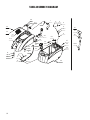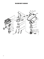
1
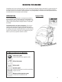
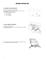
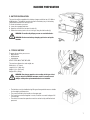
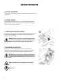
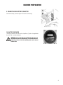
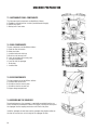
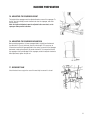
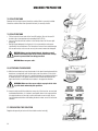
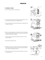
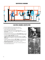
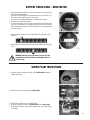
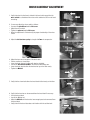
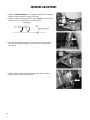
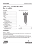
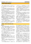
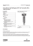
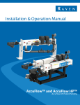
E87026-00
E88064-00
STEALTH ASD26BT
™
26” Automatic Scrubber
with Traction Drive
Operator and Parts
Manual
1001 Brown Avenue • Toledo, Ohio 43607-0127
Customer Service: 888-GO-BETCO • Fax: 800-445-5056 • Technical Service: 877-856-5954 • www.betco.com
1
TABLE OF CONTENTS
RECEIVING THE MACHINE........................................3 - 4
GENERAL SAFETY REGULATIONS.................................. 5
MACHINE PREPARATION.........................................6 - 12
OPERATION...........................................................13 - 14
TURNING OFF THE MACHINE....................................... 15
DAILY MAINTENANCE.............................................16 -17
WEEKLY MAINTENANCE............................................... 18
TROUBLESHOOTING.................................................... 19
BRUSH AND SELECTION USE...................................... 19
PARTS DIAGRAMS AND LISTINGS........................20 - 41
ELECTRICAL SYSTEM...........................................42 - 44
BATTERY CHECK CARD – HOUR METER...................... 45
WATER PLANT INSPECTIONS...................................... 45
BRAKE ADJUSTMENT................................................... 46
VACUUM SYSTEM INSPECTION................................... 46
BRUSH ADJUSTMENT.................................................. 47
SQUEEGEE ADJUSTMENT............................................ 48
CHECK LIST.................................................................. 49
MAINTENANCE SCHEDULE.......................................... 50
WEAR ITEMS................................................................ 51
WARRANTY.................................................................. 52
2
RECEIVING THE MACHINE
Immediately check, when receiving the machine, that all the materials indicated on delivery documents have been received and
also that the machine has not been damaged in transit. If it has been damaged, this damage must be immediately reported to
the shipper and also to our customer’s service department. Only acting promptly in this manner will make it possible to receive
missing material and to be compensated for damage.
INTRODUCTION
Serial # Plate
This is an automatic scrubber which, via the mechanical action of
the rotating brush and the chemical action of a water/detergent solution, can clean many types of hard flooring. As it advances, it also
collects the dirt removed and the detergent solution not absorbed
by the floor.
The machine must be used only for this purpose. Even the best
machines will only work well if used correctly and kept in good
working order. We therefore suggest you read this instruction booklet carefully and re-read it whenever difficulties arise while using the
machine. Please contact our technical service department or your
dealers if you have any questions about the machine.
SYMBOLS USED ON THE MACHINE
Solution valve symbol
Used to indicate the water regulation switch
Battery charge gauge
Battery symbol
Open book symbol
Used to tell the operator to read the manual before
using the machine
Maximum solution temperature gauge
Located near the solution tank inlet
3
TECHNICAL DESCRIPTION Measurement Unit
Stealth™ ASD26BT
Rated power
HP (W)
1.7 (1260)
Working width
In (mm)
26 (660)
Rear squeegee width
In (mm)
37.3 (948)
ft2/h (m2/h)
31,970 (2970)
in (mm)
13 (330)
RPM
225
lb. (Kg)
99.2 (45)
V / HP (V / W)
24 / 0.75 (24 / 560)
Work capacity
Brush & Pad (diameter)
Brush RPM
Brush pressure
Brush motor
Drive Type
Traction motor
Forward movement speed
V / HP (V / W) 24 / 0.20 (24 / 150)
mph (km/h)
0 - 1.9 (0 - 3)
Maximum grade
Vacuum motor
Automatic
10%
V / HP (V / W)
36 / 0.74 (36 / 550)
Vacuum motor suction
inches of water (mbar)
75.6 (192)
Solution tank capacity
Gal (l)
16 (60)
Recovery tank capacity
Gal (l)
19 (72)
Weight of machine (excluding batteries)
lb. (Kg)
253.5 (115)
Batteries
V / Ah
12 / 155 (2)
Charger
V / A
24 / 12
in x in x in
13.8 x 12.0 x 14.2
(mm/mm/mm)
(350 /305 /360)
in x in x in 54.3 x 41.5 x 26.8
(mm/mm/mm)
(1380 / 1053 / 680)
dBA
58
Battery compartment dimensions (Length / Height / Width)
Machine dimensions (Length / Height / Width)
Noise level
4
GENERAL SAFETY REGULATIONS
The regulations below must be carefully followed in order to avoid harm to the operator and damage to the machine.
• Read all labels on the machine carefully. Do not cover them for any reason and replace them immediately if they become
damaged.
• The machine must be used exclusively by authorized and trained personnel.
• When operating the machine be careful of other people.
• The machine is not designed for cleaning carpets.
• The power cable outlet must be provided with a proper ground.
• Avoid damaging the power cable of the battery charger by crushing, bending, cutting or stressing it.
• Whenever the power cable of the battery charger is damaged, immediately contact a BETCO service center.
• Do not mix different types of detergent as this may produce harmful gases.
• Do not set containers on the machine.
• Machine storage temperature is between -10°F and 130°F, never store outside under humid conditions.
• Operating conditions: room temperature between 33°F and 100°F with relative humidity between 30% to 95%.
• Only use the machine in closed areas and do not expose it directly to rain.
• Never use the machine in an explosive environment.
• Do not use the machine as a means of transport.
• Never use acidic chemicals which could damage the machine.
• Avoid running the brushes with the machine stopped; this could damage the floor.
• Never vacuum up flammable liquids.
• Never use the machine to gather dangerous powders.
• Use a powder fire extinguisher in case of fire. Do not use water.
• Do not hit against shelving or scaffolding. The operator must always be equipped with the appropriate safety device
(gloves, shoes, helmet, glasses, etc.)
• Do not use the machine on surfaces with an inclination greater than the one shown on the serial plate.
• The machine is designed to wash and dry floors simultaneously. Signal the presence of wet floors with suitable signs.
• If the machine does not work properly, perform routine maintenance. Otherwise, request the assistance of the BETCO technical service.
• When replacing parts ask for ORIGINAL spare parts from your Authorized BETCO Dealer and/or Retailer.
• Always turn off the machine and disconnect the battery connector whenever maintenance is performed.
• Never remove guards that require tools for removal.
• Never wash the machine with direct or pressurized jets of water or with corrosive substances.
• Have your BETCO service center check the machine once a year.
• To prevent the formation of scale in the solution tank filter, do not store the machine with detergent solution in the tanks.
• Before using the machine make sure that all doors and covers are positioned as shown in this operating and maintenance
manual.
• When your BETCO machine is ready to be retired, the machine must be disposed of properly. It contain oils and electronic
components. The machine was built using totally recyclable materials.
• Use only brushes furnished with the machine or those specified in the user's manual. Use of other brushes can compromise safety.
• When removing the battery, unplug the battery connection, unplug the charger and disconnect the battery terminals.
• Before recycling the machine, remove the battery.
5
MACHINE PREPARATION
1. HANDLING THE PACKED MACHINE
The machine is contained in specific packaging.
It is not possible to place more than two packages on top of each other.
The total weight is 253.5 lbs. (115 kg).
The overall dimensions of the package are:
A : 49.6 in (1260 mm)
B : 28.4 in (720 mm)
C : 65.4 in (1660 mm)
2. HOW TO UNPACK THE MACHINE
A. Remove the outer packaging.
B. The machine is attached to the pallet with wedges which block the wheels.
C. Remove these wedges.
D.Use a ramp to get the machine down from the pallet, pulling it backwards.
E. Keep the pallet for any future transport needs.
6
MACHINE PREPARATION
3. BATTERY INSTALLATION
The machine will be supplied with a battery charger and either two 12 V Wet or
AGM batteries. The batteries must be housed in the battery tray in the battery
compartment beneath the recovery tank.
To insert the batteries you must:
A. Lower the squeegee and base.
B. Open the rear latch that secures the tank (2).
C. Rotate the recovery tank as far as it will go, using the side handle (3).
WARNING: To avoid acid spillage you can use sealed batteries.
WARNING: Perform one battery charging cycle before using the
machine.
4. TYPE OF BATTERY
To power the machine you can use:
• Wet batteries
• AGM batteries
• Gel batteries
OTHER TYPES MUST NOT BE USED.
The maximum dimensions and weight are:
Width 6.8 in. (172 mm)
Length 14.2 in. (360 mm)
Height 11.2 in. (285 mm)
Weight 97 lb. (44 kg)
WARNING: Your charger must be set according to the type of battery you install. Call BETCO customer service to ensure correct
charger setting after replacement batteries are installed.
• The batteries must be handled using lifting and transportation means suitable
for the weight and dimensions.
• They must be lifted by the handles on the upper part.
• They must be connected together in series, to obtain an overall voltage of 24
V on the lugs.
• The electrical connection operations must be carried out by certified trained
personnel.
7
MACHINE PREPARATION
5. BATTERY MAINTENANCE
For maintenance and recharging, follow the instructions provided by the battery
manufacturer.
6. BATTERY DISPOSAL
When the battery reaches the end of its life, it must be disconnected by certified professional, then lifted (using the handles and suitable lifting device) to
remove it from the battery compartment.
7. CONNECTING THE BATTERY CHARGER
Beneath the recovery tank there is the battery connector (7), the battery charger
connector must be plugged into. Disconnect the battery plug and plug the
charger into the machine plug.
WARNING: This process must be carried out by qualified personnel. The incorrect or imperfect connection of the cables to the
connector can seriously harm people and damage objects.
8. RECHARGING THE BATTERIES
Perform one complete battery charge cycle before using the machine.
Avoid totally discharging the batteries! This can cause permanent damage.
Recharge as soon as the battery discharged signal light starts to flash.
WARNING: Never leave the batteries completely discharged, not
even if the machine is not being used. This can cause permanent damage to them. While recharging, keep the recovery tank
raised.
Danger of inhalation of gas and leakage of corrosive liquids.
Danger of fire.
8
MACHINE PREPARATION
9. CONNECTING THE BATTERY CONNECTOR
Connect the battery connector (2) to the machine connector (1)
10. BATTERY INDICATOR
The battery indicator uses LEDs and has 8 positions (7 yellow - charged batteries, and 1 red - run down batteries).
WARNING: A few seconds after the red indicator light comes on,
the brush motor turns off automatically. The vacuum motor will
remain in operation so that the remaining water can be removed
from the floor.
9
MACHINE PREPARATION
11. INSTRUMENT PANEL COMPONENTS
The instrument panel components are identified as follows:
A. Paddles to activate brushes / traction (located beneath the grip)
B. ON/OFF key switch
C. Battery level / hour meter
12. REAR COMPONENTS
The rear components are identified as follows:
A. Pedal to raise the brushes
B. Water level tube
C. Solution tank water inlet cap
D.Drain hose of recovery tank
E. Latch to lock down the recovery tank
F. Storage compartment
H.Lever to raise the squeegee
I. Brake lever
J. Solution filter
13. SIDE COMPONENTS
The side components are identified as follows:
A. Solution flow control valve
B. Handle to raise the recovery tank
C. Handle to raise the vacuum unit
D.Upper storage compartment
14. ASSEMBLING THE SQUEEGEE
For packaging reasons, the squeegee is supplied disassembled from the machine, and must be assembled as shown in the figure, inserting the small pin of
the squeegee into the coupling mechanism until it locks into place.
Install the squeegee vacuum hose over the squeegee shoe adapter and be certain that the vacuum hose in to the right of the squeegee lift cable.
10
MACHINE PREPARATION
15. ADJUSTING THE SQUEEGEE HEIGHT
The height of the squeegee must be adjusted based on wear of the squeegee. To
do this, turn the knob (2) counter clockwise to raise the squeegee, and clockwise to lower it.
Note: the right and left wheels must be adjusted to the same level, so the
squeegee works parallel to the floor.
16. ADJUSTING THE SQUEEGEE INCLINATION
During working operation, the rear squeegee blade is slightly bent backwards
(by about 0.2 in (5 mm)) uniformly over its entire length. If it’s necessary to
increase the bend of the squeegee blade in the center, you must tilt the squeegee
backwards, rotating the adjuster (1) counter clockwise. To increase the bend of
the squeegee at the outside edges of the squeegee, rotate the adjuster clockwise.
After adjustment, tighten the jam nut.
17. RECOVERY TANK
Check the drain hose cap (on the rear of the machine) to ensure it’s closed.
11
MACHINE PREPARATION
18. SOLUTION TANK
Remove the front inlet cap and check the solution filter is correctly installed.
Check the solution filter cover (beneath the tank) is correctly closed.
19. SOLUTION TANK
• Fill the tank with clean water in the front fill location (1) or at the rear fill
location (2) at a temperature not exceeding 120°F (50°C).
• You can check the level of solution in the tank by means of the rear sight
gauge (3).
• Add the liquid detergent into the tank, in the concentration and manner
specified by the manufacturer. The formation of excess foam could damage
the vacuum motor, so be sure to use only the correct amount of detergent.
WARNING: Always use low-foam detergent. Introduce a small
amount of defoaming liquid in the recovery tank before starting
to work to prevent foam from being generated.
WARNING: Never use pure acids.
20. ATTACHING THE BRUSHES
A. With the brush deck up, insert the brushes in the brush housing beneath the
deck base, turning them until the three pins enter the notches in the clutch
plate; turn the brush until the pin is pushed towards the coupling spring and
is locked into place. The figure shows the brush rotation direction for the
right-hand brush; the left-hand brush rotates in the opposite direction.
WARNING: Make sure there are no objects or people in the vicinity of the brush when doing this operation.
B. Swap the right and left-hand brushes every day. If the brushes are used and
have deformed bristles, it is better to reassemble them in the same position
(the right-hand one on the right, and the left-hand one on the left), to prevent the deformed bristles overloading the brush motor as well as excessive
vibration.
21. REGULATING THE SOLUTION
Regulate the quantity of water with the solution control valve (1).
12
OPERATION
1. PREPARING TO WORK
A. Connect the battery plug (1) to the machine plug
B. Turn the key (1) of the main switch to the "ON" position (clockwise). The battery charge level indicator lights will immediately come on.
C. Turn on the solution control valve (2) (solution dispenses automatically while
the brushes are turning).
D.Release the foot lever (3) and lower the brush deck. If the floor is particularly
dirty, you can apply additional pressure to the brush deck by raising the foot
lever (3) until the lock down is engaged.
E. Lower the squeegee, turning the lever (4) counter clockwise. The vacuum
motor will switch on.
F. Check that the brake (5) is released.
G.Pulling the switch levers (1), activates the brushes and the machine begins to
move forward. During the first few feet, check that the amount of solution is
correct, and that the squeegee dries the floor.
H.The machine will now start to scrub and dry until the solution tank is empty
or recovery tank is full.
13
OPERATION
2. REVERSE MOVEMENTS
To move in the reverse direction, push the switch levers (1) forward.
WARNING: When making reverse movements, raise the squeegee.
3. OVERFLOW DEVICE
The machine has a float in the filter basket that activates when the recovery tank
is full and stops airflow into the vacuum.
You must empty the recovery tank by removing the cap of the rear drain hose.
WARNING: Always wear gloves when doing this
operation to protect yourself from contact with hazardous
chemicals.
14
SHUTTING DOWN THE MACHINE
1. END OF WORK
When shutting down the machine and before you perform any type of maintenance:
A. Turn off the solution control valve using the handle (1)
B. Raise the brush deck using the foot lever (2)
C. Raise the squeegee using the squeegee lift lever (3)
D.Turn off the key switch (4)
E. Move the machine where the tanks can be drained.
F. Remove the drain hose from its holder, unscrew the drain cap and empty the
recovery tank.
G.The squeegee must be raised when the machine is not operating, to avoid
deforming the squeegee blade blades.
H.Remove the pads and clean them with water.
WARNING: Always wear gloves when doing this operation to protect yourself from contact with hazardous chemicals.
15
DAILY MAINTENANCE
1. CLEANING THE RECOVERY TANK
A. Raise the vacuum unit (1).
B. Remove the drain hose (2) and empty the tank.
C. Rinse the inside of the tank with water.
D.Close the vacuum unit on the machine and replace the drain hose cap and
drain hose.
WARNING: Always wear gloves when doing this operation to protect yourself from contact with hazardous chemicals.
2. CLEANING THE VACUUM FILTER
A. Raise the vacuum unit.
B. Remove the vacuum filter cover by rotating it clockwise.
C. Pull the filter straight down from the lid to remove it.
D.Use water to clean the walls and base of the filter.
E. Reassemble all the components.
WARNING: Always wear gloves when doing this operation to protect yourself from contact with hazardous chemicals.
3. CLEANING THE VACUUM HOSE FILTER
A. Raise the vacuum unit.
B. Rotate the inner filter (1) and remove it.
C. Use water to clean the walls and base of the filter.
D.Reassemble all the components.
WARNING: Always wear gloves when doing this operation to protect yourself from contact with hazardous chemicals.
16
DAILY MAINTENANCE
4. CLEANING THE SQUEEGEE
Ensure the squeegee is always clean, to improve drying results.
To clean:
A. Remove the squeegee vacuum hose from the squeegee shoe adapter.
B. Remove the cotter pins that attach the pins of the squeegee shoe.
C. Disassemble the squeegee from its support.
D.Loosen the wing nuts (1).
E. Remove the squeegee band clamp and squeegee blade.
F. Replace the squeegee blades.
To reassemble the squeegee, repeat the operations in the reverse order.
WARNING: Always wear gloves when doing this operation to protect yourself from contact with hazardous chemicals.
5. REMOVING THE PAD DRIVERS
A. Turn the key to the “off” position.
B. Raise the brush deck using the foot lever.
C. Rotate the brush until it comes out of the clutch as shown in the figure. The
figure shows the rotation direction to release the right-hand brush; for the
left-hand one, rotate in the opposite direction.
WARNING: Always wear gloves when doing this operation to protect yourself from contact with hazardous chemicals.
6. REPLACING THE SQUEEGEE BLADES
Check the state of wear of the squeegee blades and, if necessary, replace them.
To replace:
A. Remove the squeegee hose from the squeegee shoe adapter.
B. Push the release lever and release the right hand stud.
C. Remove the squeegee vacuum from the squeegee yoke.
D.Loosen the wing nuts.
E. Remove the squeegee band clamp and squeegee blade.
F. Replace the squeegee blades.
To reassemble the squeegee, repeat the operations in the reverse order.
WARNING: Always wear gloves when doing this operation to protect yourself from contact with hazardous chemicals.
17
WEEKLY MAINTENANCE
1. CLEANING THE SQUEEGEE HOSE
Every week, or whenever vacuum seems to be unsatisfactory, check the squeegee hose for obstructions. To clean:
A. Remove the hose from the squeegee shoe adapter on the squeegee shoe.
B. Remove the other end from the recovery tank.
C. Wash the inside of the hose with water from the end of the hose which is
connected to the recovery tank.
D.Reassemble the hose.
WARNING: Always wear gloves when doing this operation to protect yourself from contact with hazardous chemicals.
2. CHECKING THE BRAKE
Every week, check the distance between the brake pads and the wheels. If necessary, adjust them, so the pads are 0.12 inches away from the transport wheels at
a distance of 0.12 in (3 mm) when released.
3. CLEANING THE SOLUTION TANK
A. Loosen the solution tank cap.
B. Rinse with water.
C. Loosen the drain cap (1) located on the filter, and empty the tank.
WARNING: Always wear gloves when doing this operation to protect yourself from contact with hazardous chemicals.
18
TROUBLESHOOTING GUIDE
INSUFFICIENT WATER ON THE PAD
1. Verify that the solution control valve – located beneath the symbol – (1) is
turned on.
2. Verify that there is water in the solution tank.
THE MACHINE DOES NOT CLEAN WELL
1. Check the state of wear of the scrubbing pad and, if necessary, replace it.
2. Use a different kind of scrubbing pad.
THE SQUEEGEE DOES NOT DRY THE FLOOR
1. Ensure that the squeegee blades are clean.
2. Adjust the inclination of the squeegee.
3. Ensure the vacuum hose is correctly installed.
4. Check the inner filter of the recovery tank to ensure it is not dirty and, if necessary, clean it thoroughly.
5. Disassemble the entire vacuum unit and clean it.
6. Replace the squeegee blades, if worn.
7. Ensure the vacuum motor is turned on.
8. Check squeegee wheel adjustment.
TOO MUCH FOAM IS GENERATED
Check that low-foam detergent is being used. If necessary add a small amount of defoamer liquid to the recovery tank.
Remember that more foam is generated when the floors are not very dirty. Dilute the detergent more when cleaning floors that
are not very dirty.
CHOOSING AND USING THE BRUSHES
POLYPROPYLENE BRUSH (PPL)
Used on all types of floors. Good resistance to wear and tear, and hot water (no greater than 140°F (60°C)).
NYLON BRUSH
Used on all types of floors. Excellent resistance to wear and tear and hot water (even over 140°F (60°C)).
ABRASIVE BRUSH
The bristles of this type of brush are coated with highly aggressive abrasives. It is used to clean very dirty floors. To avoid floor
damage work only with the brush pressure necessary.
THICKNESS OF THE BRISTLES
Thicker bristles are more rigid and are therefore used on smooth floors or floors with small joints. On uneven floors or those with
deep joints, it is advisable to use softer bristles which can enter the gaps easier. When the bristles are worn and too short, they
will become rigid and are no longer able to penetrate and clean deep down and the brushes tends to jump.
PAD DRIVER
Pad Holders and scrub pads are recommended for cleaning smooth surfaces. There are two types of pad holder:
1. The traditional pad holder has a series of anchor points that allow the abrasive floor pad to be held and dragged while working.
2. The CENTER LOCK type pad holder not only has anchor points, but also a snap-type central locking system made of plastic
that allows the abrasive floor pad to be centered and held without any risk of it becoming detached. This type of pad driver is
recommended above all for machines with more than one brush.
19
BRUSH DECK DIAGRAM
16
8
15
4
12
23
25
9
22
11
24
20
15
27
2
18
19
7
8
13
8
A
15
11
6
19
1
A
17
5
3
26
14
21
10
20
BRUSH DECK PARTS LISTING
Item# Part # Description
Qty.
Item# Part # Description
Qty.
1
E20476 Tubing 8 ID x 12 OD x 250 L
1
17
E83935 Wire Tie
5
2
E20329 Tubing 8 ID x 12 OD x 300 L
1
18
E86275 Barbed Elbow, 3/8"
1
3
E86143 Splash Guard
1
19
E20481 Fitting, Hose Barb 1/4" x 10mm
2
4
E82710 Hose, 8 OD x 5 ID x L 105
2
20
E20637 Brush Motor Cover
1
5
E20416 Brush Deck
1
21
E20475 Lock Washer M4 Zinc
4
6
E20631 Manifold
1
22
E20607 Hose Clamp
1
7
E20474 Washer, Nylon, 18mm ID x 30mm OD x 3mm T 1
23
E20627 Plug, 3/8" Male
1
8
E83932 Bushing
3
24
E81552 Fitting, Brass, 1/4" x 7mm
2
9
E82309 Spring, 11.8x1.2x15mm Zinc Compression
1
25
E20581 Plug, 1/4" Male
4
10
E83857 Hex Bolt M4x12 Zinc
4
26
E20187 Plug
1
11
E83802 Hex Bolt M8x30 Zinc
2
27
E20631 Manifold
1
12
E83827 Hex Bolt M8x45 Zinc
1
-
E81668 Pad Driver
13
E81709 Nyloc Hex Nut, M8 Zinc
3
-
E81681 Brush, General Purpose
2
14
E83037 Flat Washer M4x12x1.6 Zinc
4
-
E82850 Brush, Medium Duty
2
15
E83404 Flat Washer M9x24x2.5 Zinc
7
-
E82851 Brush, Heavy Duty
2
16
E83832 Flat Washer M8.5x30x3 Nylon
2
-
E82852 Brush, Tynex Stripping
2
2
21
BRUSH DRIVE DIAGRAM
36
21
49
14
37
43
32
13
46
25
24
64
15
6
30
63
4
50
29
33
38
18
47
58
12
56
9
59
52
62
23
45
28
54
48
19
42
22
31
17
16
5
57
47
57
26
10
41
65
1
34
44
2
11
60
56
55
8
3
52
35
39
40
7
61
51
22
20
27
53
BRUSH DRIVE PARTS LISTING
Item# Part # Description
Qty.
Item# Part # Description
Qty.
1
E82424 Motor Pulley 1
34 E83547 Hex Bolt M6x16 Zinc 4
2
E85723
1
35 E82772 Hex Bolt M6x20 Zinc 1
3
E20428 Tensioner Bracket
1
36 E82738 Brush Motor 24VDC 560W 1
4
E20491 Tensioner Arm 1
37 E83524 Bushing 3
5
E81957 Pad Driver Retainer Clip 2
38 E88014 Bushing 1
6
E20007 Stud Bolt 12
39 E88007 Bushing 1
7
E88009 Bushing 1
40 E83698 Tension Spring 1
8
E88008 Adjuster 1
41 E83491 Spring 2
9
E87279 Bushing 1
42 E81953 Spring, Brush Lock 2
10 E83823 Screw M5x20/ SS Custom 1
43
E81656 Retaining Ring - Internal 3
11 E20615 Flat Washer M6.5x18x4 1
44 E83700 Shaft Key 1
12 E20546 Spacer 1
45 E83923 Bearing, 6004 2RS
13 E86216 Spacer 2
46 E81657 Bearing 5
14 E87281 Spacer
2
47 E83833 Hex Bolt M8x25 Zinc 6
15 E20517 Brush Pulley 1
48 E83801 Hex Bolt M8x35 Zinc 1
16 E20508 Brush Pulley 1
49 E83830 Hex Bolt M8x40 Zinc 3
17 E20564 Brush Deck 1
50 E87285 Hex Bolt M8x50 Zinc 1
18 E20311 Bushing 1
51 E88017 Screw, Pan Hd Phil Self Tap M4.8x13 SS 6
19 E20622 Idler Pulley 1
52 E81709 Nyloc Hex Nut, M8 Zinc 12
20 E20419 Brush Deck Cover 1
53 E83381 Nyloc Hex Nut, M10 Zinc 1
21
E20624 Brush Deck Lift Bracket 1
54 E88015 Nyloc Hex Nut, M20x17 Zinc 2
22 E20061 Brush Deck Lift Bracket 1
55 E88010 Hex Nut, M5 6
23 E20335 Sheath 1
56 E82774 Flat Washer M6x12x1.6 SS 5
24 E87284 Shaft 2
57 E81874 Flat Washer M8x17x1.6 Zinc 12
25 E88110 Flat Washer M6.1x60x3 Nylon 1
58 E20126 Cupped Spring Washer M8x18x1 2
26 E81926 Band Clamp 1
59 E83404 Flat Washer M9x24x2.5 Zinc 3
27 E81926 Band Clamp 1
60 E81918 Flat Washer M9x32x2.5 Zinc 1
28 E20535 Clutch Plate 2
61 E82773 Flat Washer M10x21x2 Zinc 1
29 E83489 Rings 2
62 E20253 Flat Washer M21x60x3 Nylon 2
30 E20229 Flexible Coupling 2
63 E20350 Flat Hd Soc Machine Screw M8x50 Zinc 1
31 E82303 Pipe 2
64 E81808 Poly Vee Belt 1
32 E83895 Wheel 80 OD x 23 W 3
65 E20427 Plug 4
33 E20086 Hex Bolt M5x25 Zinc 2
Idler Pulley 2
23
BRUSH DECK LIFT DIAGRAM
23
14
27
13
8
18
6
32
22
33
21
5
1
17
25
3
24
4
19
31
19
29
28
16
9
11
26
30
17
20
7
12
24
10
2
28
24
28
29
15
BRUSH DECK LIFT PARTS LISTING
Item# Part # Description
Qty.
Item# Part # Description
Qty.
1
E82689 Spring, 15x2x60mm Galv Extension
1
18
E88011 Hex Bolt, M10 x 30 Zinc
1
2
E20219 Brush Deck Lift Arm Weldment
1
19
E83852 Hex Nut, M6x5
2
3
E20220 Brush Deck Lift Arm Linkage
1
20
E83656 Hex Nut, M8x6.5 Zinc
1
4
E20062 Brush Deck Lift Idler Arm
1
21
E82808 Hex Jam Nut, M8X5 Zinc
1
5
E20282 Brush Deck Lift Foot Pedal
1
22
E83875 Hex Jam Nut, M10X6 Zinc
1
6
E20283 Foot Pedal Latch Plate
1
23
E81673 Hex Nyloc Nut, M3 Zinc
2
7
E20063 Bushing
1
24
E83550 NyLoc Hex Nut, M6 Zinc
2
8
E88279 Micro Switch Sealed
1
25
E86853 Nyloc Hex Nut, M8 Zinc
1
9
E20088 Hex Bolt M6x18 Zinc
1
26
E83381 Nyloc Hex Nut, M10 Zinc
1
10
E82772 Hex Bolt M6x20 Zinc
1
27
E81874 Flat Washer M8x17x1.6 Zinc
1
11
E20090 Hex Bolt M6x25 Zinc
1
28
E83404 Flat Washer M9x24x2.5 Zinc
5
12
E83932 Bushing
1
29
E83704 Lock Washer M8x13x2.2 Zinc
2
13
E82285 Bushing
2
30
E82773 Flat Washer M10x21x2 Zinc
1
14
E81917 Hex Bolt M8x20 Zinc
1
31
E20130 Shock Absorber
1
15
E83833 Hex Bolt M8x25 Zinc
1
32
E20533 Hex Bolt M3x20 SS
2
16
E83801 Hex Bolt M8x35 Zinc
1
33
E20635 Abrasive Antislip Tape
1
17
E83830 Hex Bolt M8x40 Zinc
2
25
SQUEEGEE DIAGRAM
27
18
19
23
21
8
22
10
17
25
16
13
23
20
15
28
24
25
9, 29
12
23
24
1
26
14
2
7
5
26
3
11
4
6
SQUEEGEE PARTS LISTING
Item# Part # Description
Qty.
Item# Part # Description
Qty.
1
E82275 Pin, Adjustable Mounting M10 Zinc
1
16
E82253 Bushing, Brass OD 11.95mm x ID 8.9mm x L 8.45mm2
2
E82280 Pin, Fixed Mounting M10 Zinc
1
17
E83802 Hex Bolt M8x30 Zinc
2
3
E81834 Squeegee Blade, Polyurethane 38" x 1 1/2" x 1/8" 1
18
E82707 Set Screw Hex Soc Flat End M6x40 SS
2
4
E81835 Squeegee Blade, Polyurethane 38 1/4" x 1 1/2" x 1/8"1
19
E83831 Flat Hd Soc Machine Screw M6x20 SS
2
5
E20617 Band Clamp
1
20
E81848 Flat Hd Soc Machine Screw M6x25 SS
10
6
E20012 Band Clamp
1
21
E20345 Flat Hd Soc Machine Screw M8x14 Zinc
2
7
E20573 Squeegee Shoe
1
22
E20247 Flat Hd Soc Machine Screw M8x18 Zinc
2
8
E20498 Brass Washer - Custom
4
23
E20114 Hex Jam Nut, M6X3 SS
16
9
E82307 Squeegee Vacuum Adapter, Vertical
1
24
E83550 NyLoc Hex Nut, M6 Zinc
6
10
E20572 Squeegee Shoe Extender
1
25
E81874 Flat Washer M8x17x1.6 Zinc
4
11
E20077 Squeegee Shoe Extender
1
26
E83948 Lock Washer M10x18x2.2 Zinc
2
12
E83971 Gasket
1
27
E81435 Knob, M6 8-Lobe Nylon Female
2
13
E82451 Wheel 45 OD x 25 W
2
28
E83591 Knob, M6 2-Arm Nylon Female
10
14
E81833 Squeegee Blade, Gum Rubber 38 1/4" x 1 3/4" x 1/8"1
-
E82506 Squeegee Assembly
1
15
E83914 Hex Bolt M6x20 SS
29
E89559 Squeegee Vacuum Adapter, Horizontal
1
4
27
SQUEEGEE YOKE DIAGRAM
17
1.25
13
1.21
1.17
1.13
1.7
1.1
14
1.11
1.29
7
1.20
3
1.22
5
1.9
1.18
6
2.4
1.8
1.5
1.28
1.22
5
1.16
12
1.26
11
1.33
1.23
1.6
1.31
4
9
1.4
1.31
28
15
1.3
1.15
1.24
10
1.32
1.10
1.27
16
1.14
1.30
1.2
8
2.1
2.2
2.3
1.17
1.33
1.26
1.19
1.34
1.12
SQUEEGEE YOKE PARTS LISTING
Item# Part # Description
Qty.
Item# Part # Description
Qty.
1
E20623 Squeegee Yoke ASM
1
1.28 E83278 Flat Washer M6.5x24x2 Zinc
2
1.1 E20010 Pivot Pin
1
1.29 E82774 Lock Washer, M6 Zinc
2
1.2 E82389 Tie Rod, M6 Square Head Zinc
1
1.30 E88238 Flat Washer, M8x17x1.6 SS
1
1.3 E82265 Knob, Squeegee Pitch Adjustment
1
1.31 E85722 Flat Washer M13x24x2.5 Zinc
2
1.4 E83331 Knob, M8 Round Nylon Female
2
1.32 E81406 External Serrated Lock Washer M13x18 Zinc
1
1.5 E85776 Pivot Connector
1
1.33 E82314 Nyloc Hex Nut, M6 SS
3
1.6 E20078 Squeegee Wheel Support
2
1.34 E88280 Wheel 80 OD x 23 W
2
1.7 E81880 Squeegee Yoke
1
2
E88278 Squeegee Lift Rod ASM
1
1.8 E20079 Threaded Adjuster Rod
2
2.1 E82279 Spring, 20x3x48mm Custom Galv Extension
1
1.9 E20080 Ballast
2
2.2 E82761 Washer 6x12x1.6
1
1.10 E86252 Latch, Squeegee Connector
1
2.3 E20382 Nyloc Hex Nut, M5 x 5 Zinc
1
1.11 E20090 Hex Bolt M6x25 Zinc
2
2.4 E88250 Squeegee Lift Cable
1
1.12 E82274 Bushing
2
3
E20313 Squeegee Lift Lever
1
1.13 E20091 Spring
2
4
E88279 Micro Switch Sealed
1
1.14 E82703 Spring, 16.6x2x23mm Galv Compression
1
5
E20337 Flat Washer M17x40x2 Delrin
2
1.15 E82453 Spring, 10x1.1x38 SS Extension
1
6
E20231 Bushing
1
1.16 E86158 Spring, 86mm Galv Torsion Custom
1
7
E82455 Hex Bolt M10x35 Zinc
1
1.17 E85498 E Style Circlip
2
8
E83838 Screw, Flat Hd M4x15 Zinc
4
1.18 E86159 Hex Bolt M6x50 Zinc
1
9
E82317 Hex Jam Nut, M5X3.5 Zinc
1
1.19 E83866 Hex Bolt M6x60 SS
2
10
E81673 Hex Nyloc Nut, M3 Zinc
2
1.20 E20098 Hex Bolt M8x18 Zinc
1
11
E83381 Nyloc Hex Nut, M10 Zinc
1
1.21 E83672 Hex Jam Nut, M8x5 SS
2
12
E20295 Flat Washer M10.5x32x4Zinc
1
1.22 E83824 Square Nut, M8 SS
3
13
E20533 Hex Bolt M3x20 SS
2
1.23 E83550 NyLoc Hex Nut, M6 Zinc
2
14
E20382 Nyloc Hex Nut, M5 x 5 Zinc
1
1.24 E83550 NyLoc Hex Nut, M6 Zinc
1
15
E20638 Knob
1
1.25 E86853 Nyloc Hex Nut, M8 Zinc
1
16
E20641 Bracket
1
1.26 E82761 Washer 6x12x1.6
6
17
E20641 Bracket
1
1.27 E82798 Washer, 6x18x1.5
1
29
MAIN FRAME DIAGRAM
20
32
31
27
33
7.5
34
7.12
25
7.10
3
7.3
12
5
37
27
26
27
7.4
12
38
6
19
16
26
39
21
11
17
14
26
13
18
23
2
15
40
24
28
22
36
14
30
30
15
29
25
2
1.3
1.2
1.4
1.1
7.13
27
4
10
30
7.1
26
9
12
7.2
8
35
7.11
7.6
7.8
7.7
7.9
7.14
MAIN FRAME PARTS LISTING
Item# Part # Description
Qty.
Item# Part # Description
Qty.
1
E20003 Axle Shaft ASM
2
12
E82772 Hex Bolt M6x20 Zinc
7
1.1
E20478 Axle Shaft
1
13
E81056 Spring
1
1.2
E20482 Spacer
1
14
E83974 Hex Bolt M6x30 Zinc
9
1.3
E20081 Bearing Block
1
15
E81917 Hex Bolt M8x20 Zinc
2
1.4
E83923 Bearing
2
16
E87285 Hex Bolt M8x50 Zinc
1
2
E20013 Spacer
2
17
E20489 Soc Hd Cap Screw M6x20 Zinc
2
3
E20492 Brake Arm Weldment
1
18
E83852 Hex Nut, M6x5
2
4
E20407 Main Frame Weldment
1
19
E83656 Hex Nut, M8x6.5 Zinc
1
5
E20221 Frame Bracket
1
20
E82808 Hex Jam Nut, M8X5 Zinc
2
6
E20222 Plate
1
21
E83550 NyLoc Hex Nut, M6 Zinc
2
7
E20518 Brake Lever ASM
1
22
E20249 Nyloc Hex Nut, M12x15 Zinc
1
7.1
E20595 Brake Lever
1
23
E20250 Cage Nut M5
2
7.2
E20522 Brake Lever Bracket
1
24
E81618 Flat Washer M5x10x1 SS
2
7.3
E81928 Latch Lock
1
25
E82761 Flat Washer M6x12x1.6 Zinc
12
7.4
E82255 Spring
1
26
E82798 Flat Washer M6x18x1.5 Zinc
11
7.5
E83491 Spring
1
27
E82774 Flat Washer M6x12x1.6 SS
11
7.6
E20341 Hex Bolt M4x16 Zinc
1
28
E85722 Flat Washer M13x24x2.5 Zinc
1
7.7
E83974 Hex Bolt M6x30 Zinc
1
29
E81438 External Serrated Lock Washer M6 Zinc
8
7.8
E81917 Hex Bolt M8x20 Zinc
1
30
E83868 External Serrated Lock Washer M8 Zinc
2
7.9
E20112 Hex Nut, M6x6 Zinc
2
31
E88002 Battery Tray
1
7.10
E83867 Nyloc Hex Nut, M4x6 Zinc
1
32
E20360 Hex Bolt M6x45 Zinc
4
7.11
E83550 NyLoc Hex Nut, M6 Zinc
1
33
E20379 Hex Bolt M12x40 Zinc
1
7.12
E81709 Nyloc Hex Nut, M8 Zinc
1
34
E20297 Flat Hd Soc Machine Screw M8x16 Zinc
2
7.13
E20423 Brake Handle Grip
1
35
E81971 Wheel Cap 2
7.14
E20537 Brake Cable
1
36
E88282 Wheel 200 OD x 50 W
2
8
E81915 Flat Washer M8.2x32x4 Zinc
2
37
E20175 Brake Pad M8x17
2
9
E82834 Pivot Block
4
38
E88283 Chassis Splash Guard
1
10
E86182 Drive Motor 24VDC 150W
1
39
E20176 Band Clamp
1
11
E20084 Hex Bolt M5x16 SS
2
40
E20177 Caster
1
31
TANK ASSEMBLY DIAGRAM
4.8
4.1
4.11
1
8
9
6
13
22
17
6
23
4.3
4.10
4.4
4.5
7
2
5.1
5.4
5.7
5.5
5.3
5.9
5.2
3
11
14
20
5.8
18
12
32
4.9
4.6
4.2
15
21
8
4.7
16
20
5.6
19, 24
TANK ASSEMBLY PARTS LISTING
Item# Part # Description
Qty.
Item# Part # Description
Qty.
1
E88499 Hose, Vacuum
1
5.7 E82269 Barbed Fitting, 3/8 in.
1
2
E20004 Tubing 12 ID x 200 L
1
5.8 E20185 Cap
1
3
E88288 Hose, Glass Reinforced 17 OD x 12 ID x 820 L
1
5.9 E20201 Soltuion Tank
1
4
E20228 Recovery Tank Assembly
1
6
E83833 Hex Bolt M8x25 Zinc
2
4.1 E82341 Gasket
1
7
E20107 Screw, Pan Hd Phil Self Tap M4.2x16 SS
4
4.2 E20107 Screw, Pan Hd Phil Self Tap M4.2x16 SS
2
8
E82808 Hex Jam Nut, M8X5 Zinc
2
4.3 E20432 Hose Clamp
1
9
E20127 Flat Washer M9x18x1.5 Zinc
2
4.4 E88164 Male Connector 1/4 x 1/2 for Simpla 20
1
11
E86275 Barbed Elbow, 3/8"
1
4.5 E20468 Flat Hd Phil Machine Screw M5x12 Zinc
1
12
E20651 T-Fitting, 3/8" Male/Double Female Nylon
1
4.6 E20413 Latch
1
13
E20325 Hose Clamp
1
4.7 E88285 Filter, Cage
1
14
E82269 Barbed Fitting, 3/8 in.
1
4.8 E20186 Elbow
1
15
E20399 Pivot Plate
2
4.9 E88286 Hose, Drain
1
16
E20190 Spacer Block
2
4.10 E20202 Recovery Tank
1
17
E88260 Lanyard
1
4.11 E20189 Fitting, Threaded Nylon
1
18
E85762 Hose Clamp
2
5
E20376 Solution Tank Assembly
1
19
E88499 Hose, Vacuum (21.25" For Vertical Shoe)
1
5.1 E82429 Cap
1
20
E83920 Clamp 9x300 4,8x360 black
2
5.2 E82612 Filter
1
21
E88500 Fitting, Hose D38, W1.5, L50
1
5.3 E20107 Screw, Pan Hd Phil Self Tap M4.2x16 SS
2
22 E22074 Plug, Vac Lid Bale 2
5.4 E88164 Male Connector 1/4 x 1/2 for Simpla 20
1
23 E22072 Bale, Vac Lid
1
5.5 E20468 Flat Hd Phil Machine Screw M5x12 Zinc
1
24
E82478 Hose, Vacuum (25" For Horizontal Shoe)
5.6 E20627 Plug, 3/8" Male
1
1
33
VACUUM UNIT DIAGRAM
2.27
2.8
2.19
2.11
2.13
2.30
2.26
2.23
2.9
2.14
2.29
2.3
1
2.18
3
2.17
2.10
2.15
2.16
4
2.24
2.22
2.28
2.31
2.32
2.7
2.12
2.1
2.25
2.26
2.4
2.2
2.6
2.20.2
2.21
2.20.1
2.20.3
2.20.4.2
2.5
34
2.20
VACUUM UNIT PARTS LISTING
Item# Part # Description
Qty.
Item# Part # Description
Qty.
1
E20265 Plate
2
2.19 E20064 Support Bracket
1
2
E20066 Recovery Tank Cover ASM
1
2.20 E88291 Vacuum Motor 36VDC 550W
1
2.1 E20305 Mounting Ring
1
2.20.1 E83897 Connector, Electrical Housing 30A
2
2.2 E20652 Sound Deadening Foam
1
2.20.2 E83883 Lug, Electrical 30A
2
2.3 E20180 Sound Deadening Foam
1
2.20.3 E83935 Wire Tie
2
2.4 E20179 Sound Deadening Foam
1
2.20.4 E88291 Vacuum Motor 36VDC 550W
1
2.5 E20178 Sound Deadening Foam
1
2.20.4.1 E88291 Vacuum Motor 36VDC 550W
1
2.6 E20266 Sound Deadening Foam
1
2.20.4.2 E20525 Carbon Brush
2
2.7 E88292 "Filter, Cage"
1
2.21 E81006 Vacuum Splash Guard
1
2.8 E20486 Bushing
1
2.22 E20122 Flat Washer M5 x 15 x 1.5 SS
5
2.9 E20384 Vacuum Motor Cover
1
2.23 E88290 Hose, Vacuum 1-1/2" x 22-1/4"
1
2.10 E20191 Deflector
1
2.24 E20440 Sound Deadening Foam
1
2.11 E20199 Recovery Tank Cover
1
2.25 E83796 Screw, Pan Hd Phil Self Tap M4.2x16 Zinc
2
2.12 E81710 Hose Clamp
1
2.26 E83838 Screw, Flat Hd M4x15 Zinc
2
2.13 E20325 Hose Clamp
2
2.27 E20442 Button Hd Soc Machine Screw M5x16 Zinc
1
2.14 E20181 Sound Deadening Foam
1
2.28 E20084 Hex Bolt M5x16 SS
5
2.15 E20184 Sound Deadening Foam
1
2.29 E20712 Magnet
1
2.16 E20183 Sound Deadening Foam
1
2.30 E20192 CHIPBOARD SCREW M3x12 Zinc
1
2.17 E20182 Sound Deadening Foam
1
2.31 E22075 Hook, Vac Lid Bale 1
2.18 E88289 Gasket
1
2.32 E22076 Screw, M4 x 10
2
35
SOLUTION CONTROL DIAGRAM
2*
18
14
5
20
8.2
15
8.1
16
4
1
6
10
22
12
3
9
17
11
21
13
36
23
19
SOLUTION CONTROL PARTS LISTING
Item# Part # Description
Qty.
Item# Part # Description
Qty.
1
E20004 Tubing 12 ID x 200 L
1
12
E83617 O-Ring, 14x2.5mm Buna-N
1
2
E20530 Tubing 12 ID x 460 L
1
13
E20098 Hex Bolt M8x18 Zinc
1
3
E82693 Hose, 17 OD x 12 ID x L 420
1
14
E83838 Screw, Flat Hd M4x15 Zinc
4
4
E82447 Fitting, 1/2" NPT & 1/2" Barbed Nylon
1
15
E86853 Nyloc Hex Nut, M8 Zinc
1
5
E88207 Filter Assembly, Inline Double Female 1/2" NPT 1
16
E81874 Flat Washer M8x17x1.6 Zinc
1
6
E20457 Bracket
1
17
E20253 Flat Washer M21x60x3 Nylon
2
8
E20463 Instrument Panel ASM
1
18
E85762 Hose Clamp
7
8.1 E20332 Panel
1
19
E83361 Ball Valve, 5/8 Double Female
1
8.2 E88293 Battery Check Card, Hour Meter
1
20
E81446 Fitting, 1/2" NPT & 1/2" Barbed Nylon Elbow
1
9
E82705 Valve Lever
1
21
E83616 Cap, 1/2" NPT Nylon
1
10
E82322 Solenoid Valve, 24v 10w 3-Port Nylon
1
22
E20433 Ring Nut 1/2"
1
11
E83858 Oval Hd SL Machine Screw M4x12 SS
1
23
E82269 Barbed Fitting, 3/8 in.
2
37
HANDLEBAR DIAGRAM
22
6
25
11
30
23
3
1.2
1.3
9
18
3
1.5
14
26
2.18
15
2.8
2.3
2.6
12
21
4
8
2.11
2.15
2.9
16
10
19
24
2.20
2.21
27
28
2.2
5
17
2.5
2.16
2.4
2.10
13
2.1
2.17
2.21
17
2.7
7
38
1.1
1.4
29
2.19
2.14
2.12
2.13
HANDLEBAR PARTS LISTING
Item# Part # Description
Qty.
Item# Part # Description
Qty.
1
E82351 Key Switch Assembly w/Keys
1
3
E20625 Electrical Control Panel ASM
1
1.1 E83173 Contact, Key Switch
1
4
E83836 Hex Bolt M5x16 Zinc
1
1.2 E83316 Key Switch
1
5
E20288 Soc Hd Cap Screw M8x30 Zinc
4
1.3 E83316 Key Switch
1
6
E20242 Pan Hd Phil Machine Screw M3x20 Zinc
2
1.4 E81358 Switch Flange
1
7
E81672 Flat Hd SL Machine Screw M3x10 SS
2
1.5 E83315 Switch Key
1
8
E20111 Flat Hd Soc Machine Screw M6x20 Zinc
2
2
E20223 Drive Control
1
9
E20346 Flat Hd Soc Machine Screw M8x25 SS
2
2.1 E20330 Ball Stud M10x22.5
2
10
E82317 Hex Jam Nut, M5X3.5 Zinc
2
2.2 E81597 Circuit Breaker 10 amp, 1/4" Tab Terminals
1
11
E81673 Hex Nyloc Nut, M3 Zinc
2
2.3 E20556 Plate
1
12
E20121 Flat Washer M5x15x1.5 Zinc
2
2.4 E81763 Cam
1
13
E81874 Flat Washer M8x17x1.6 Zinc
4
2.5 E82304 Spring, 20.2x1.3x20.8mm Steel Torsion
1
14
E83959 Circuit Breaker 20A
1
2.6 E20341 Hex Bolt M4x16 Zinc
1
15
E87296 Drain Hose Clip
1
2.7 E20242 Pan Hd Phil Machine Screw M3x20 Zinc
2
16
E20442 Button Hd Soc Machine Screw M5x16 Zinc
1
2.8 E20243 Pan Hd Phil Machine Screw M3x30 Zinc
2
17
E81046 Lock Washer M8 Zinc
7
2.9 E20248 Hex Nut, M4x4 Zinc
1
18
E83952 Circuit Breaker 30A
1
2.10 E82317 Hex Jam Nut, M5X3.5 Zinc
2
19
E20614 Soc Hd Cap Screw M8x20 Zinc
3
2.11 E81673 Hex Nyloc Nut, M3 Zinc
4
20
E88299 Cover, Thermal Switch
1
2.12 E83550 NyLoc Hex Nut, M6 Zinc
1
21
E20576 Cap, M10x13 Threaded Poly
1
2.13 E83037 Flat Washer M4x12x1.6 Zinc
1
22
E88300 Lever, Left Switch
1
2.14 E82798 Flat Washer, M6x18x1.5 Zinc
1
23
E88301 Lever, Right Switch
1
2.15 E82270 Micro Switch
3
24
E20267 Door
1
2.16 E81625 Shank, M5x32 Female Threaded Nylon
2
25
E88267 Switch Cam
1
2.17 E20466 Insert, M3x9 Zinc
1
26
E20200 Handlebar Housing
1
2.18 E20360 Hex Bolt M6x45 Zinc
1
27
E20400 Hinge
1
2.19 E20362 Set Screw Hex Soc Dog Point M5x30 Zinc
1
28
E20192 CHIPBOARD SCREW M3x12 Zinc
2
2.20 E20469 Flat Washer M3 SS
2
29
E88408 Knob
1
2.21 E20382 Nyloc Hex Nut, M5 x 5 Zinc
2
30
E20713 Potentiometer
1
39
ELECTRICAL COMPONENTS DIAGRAM
19
10
22
16
17
18
21
3
9
1
13
24
5
20
7
8
11
8
40
12
14
6
11
15
4
2
ELECTRICAL COMPONENTS PARTS LISTING
Item# Part # Description
Qty.
Item# Part # Description
Qty.
1
E20065 Bracket
1
13
E20377 Rivet, M2.4x8 AL
2
2
E20646 Chopper Card
1
14
E20484 Fuse Block
1
3
E83628 Contactor 24VDC
2
15
E83170 Fuse, 80 Amp
1
4
E83159 Relay 24VDC 20A
2
16
E20448 Bracket
1
5
E20097 Hex Bolt M8x40 SS
2
17
E20129 Cap
4
6
E20248 Hex Nut, M4x4 Zinc
2
18
E20468 Flat Hd Phil Machine Screw M5x12 Zinc
5
7
E83672 Hex Jam Nut, M8x5 SS
2
19
E81998 Pan Hd Phil Machine Screw M4x10 SS
2
8
E20115 Hex Nut, M8x6.5 Brass
4
20
E20475 Lock Washer M4 Zinc
2
9
E20479 Spring Nut M5
2
21
E20301 Flat Hd Phil Machine Screw M4x20 Zinc
2
10
E81738 Flat Washer M4x12x3 Zinc
2
22
E88456 Electrical Cover Rubber Flap
1
11
E20124 Flat Washer M8x17x1.6 SS
6
24
E20368 Resistor
1
12
E20252 Lock Washer M8x13x2.2 SS
2
41
ELECTRICAL DIAGRAM
42
ELECTRICAL LISTING
Item# Part # Description
Item# Part # Description
1
E82351 Key Switch
12
E20619 SB175 Red Electrical Connector
2
E88293 Hour Meter
13
E20619 SB175 Red Electrical Connector
3
E20646 Chopper Card
F
E83972 Fuse 30A fasten
4
E83628 Contactor 24VDC
N
E83159 Relay 24VDC 20A
5
E83628 Contactor 24VDC
R
E20368 Resistor
6
E83170 Fuse, 80 Amp
MI 1
E82270 Micro Switch
7
E83952 Circuit Breaker 30A
MI 2
E82270 Micro Switch
8
E83959 Circuit Breaker 20A
MI 3
E82270 Micro Switch
9
E82322 Solenoid Valve
MI 4
E88249 Micro Switch
9A
E81035 Solenoid Valve
MI 5
E88249 Micro Switch
10
E20402 Electrical Connector 30A
M2
E88291 Vacuum Motor 36VDC 550W
11
E20402 Electrical Connector 30A
M3
E86182 Drive Motor 24VDC 150W
43
ELECTRICAL DIAGRAM
VACUUM
MOTOR
ELECTRIC HARNESS INSPECTION
1. Verify the functionality of the variable speed control card.
2. If necessary adjust the variable speed control card as follows:
• Lift up at least one of the traction wheels.
• Remove the handlebar to gain access to the electric controls.
• Place voltage meter probes on the faston M+ and M- of the variable speed
control card.
• Turn on the key master switch.
• Pull the lever until you hear the forward first micro switch click (first speed).
• The tester has to show a voltage between 14 and 15 V. If the reading is different adjust the trimmer “MA Lenta” (first speed).
• Completely pull the switch lever until the second (maximum) speed micro
switch is pressed. A voltage of 24 V (the same as the battery voltage) should
be observed.
• Acceleration adjustment: Adjust the “ACC” trimmer to let it be between 30°
and 45° respect the central position rotating clockwise. Verify that with this
adjustment the machine reaches maximum speed in 4 seconds.
• Check the backwards direction.
• Check the braking power of the traction motor. At maximum speed the machine should stop in about 3 feet.
44
BATTERY CHECK CARD – HOUR METER
1. Verify that when turning on the machine the battery check card has the
following starting sequence:
• Turning on of the LED which correspond to the set-up (red LED = “0”).
• Turning on of all the LEDs (check of the lamps)
• Turning on of the LEDs depending on the charge of the battery
2. Verify the hour meter functionality
• To verify which is the set-up you turn on the machine and check which
is the first LED that turns on. Counting the LEDs since the left side any
LED correspond to a position and the LED which turn on correspond to
the current set-up.
• Verify that if the machine uses wet cell batteries the adjustment is on
position 1.
1
• Verify that if the machine uses GEL batteries the adjustment is on position 4.
4
WARNING: A wrong set-up of the battery control card can
compromise the battery efficiency and damage then in irreversible way.
WATER PLANT INSPECTIONS
1. Verify the cleanness and functionality of the solution filter under the
solution tank plug.
2. Check cleanness and sealing of the solution filter.
3. Confirm that solution tank is completely filled.
4. Verify the sealing of the hoses, solenoid valve and the water valve.
5. Verify that the solution, with valve completely open, falls continuously
on the floor.
45
BRAKE ADJUSTMENT
1. Adjust the brake pads on the wheels to lock the wheels when the brake lever
reaches the third ratchet notch.
2. To adjust the pads:
• Unscrew the M8 jam nut.
• Adjust the pad.
• Tighten the M8 jam nut.
VACUUM SYSTEM INSPECTION
1. Confirm that the float filter is clean.
2. Check the air sealing of the vacuum unit on the recovery tank.
3. Verify the connections and the sealing of the vacuum hoses and the squeegee
hoses.
4. Check the sealing of the squeegee hose adapter.
6. Vacuum micro switch adjustment:
7. Adjust the vacuum micro switch in a manner that when the cam on the
squeegee lift lever pushes on the micro switch there is 0.5 mm of clearance
between the micro switch roller and the cam.
46
BRUSH ASSEMBLY ADJUSTMENT
1. Verify that when the foot lever is locked in the brush deck up position the
micro switch is activated and the micro switch actuator has 0.5 mm of travel
remaining.
2. If necessary adjust the micro switch as follows:
• Unscrew the nyloc M3 nut and the M3 screw.
• Adjust the micro switch.
• Tighten the nyloc nut and the M3 screw.
• When the adjustment is finished verify the proper functionality of the micro
switch.
3. Adjust the belt tensioner spring to a length of 27 mm in compression.
4. Adjust the transversal inclination of the brush deck:
• Put the machine on a level floor.
• Lower the brush base on the floor with brushes installed.
• Loosen the bolt and the nut M8 on the left brush deck lifting arm.
• Lower the brush deck to allow the two brushes lay on the floor evenly.
• Tighten the M8 bolt.
5. Verify that the shown bolt allows the brush deck to float evenly on the floor.
6. Verify that the brushes can be removed from the brush deck if necessary:
• Lift up the brush deck.
• Loosen the M6 jam nut.
• Adjust the M6 bolt until the brushes have enough space to be removed from
the brush deck.
• Verify that with the brush base does not interfere with the solution tank.
47
SQUEEGEE ADJUSTMENT
1. Adjust the inclination adjuster of the squeegee assembly until the squeegee
blade has a uniform deflection along its entire length.
2. Adjust the height of the squeegee wheels using the knob such that the squeegee blade has an inclination between 30 and 45 degrees.
3. Verify that the squeegee assembly in up position does not interfere with the
brush deck foot lever by adjusting the nyloc nut internal to the squeegee
cable spring.
4. Adjust the spring tension so that the squeegee blades deflect when they
contact the floor by tightening the nyloc nut.
48
CHECK LIST
Functional check of the machine
Check the functionality of switches and warning lamps.
Check the functionality of the switch lever.
Check the functionality of the brush deck.
Check the functionality of the brush motor.
Check the functionality of the solenoid valve.
Check the functionality of the vacuum motor.
Check the functionality of the brakes.
Check the functionality of batteries and power cables.
Functional test of the machine
Fill the tanks completely and verify that there are no leaks.
Adjust the inclination and the height of the squeegee blades.
Adjust the inclination of the brush deck.
Check the function of the parking brake.
Verify the forward and backward movement, acceleration and braking.
Final test
Check all the functions: washing, drying and movement.
49
MAINTENANCE SCHEDULE
RECOMMENDED SERVICE INTERVALS
(HOURS)
Stealth ASD26BT
Machine components
BATTERIES
Suggested replacement
DAILY
50
100
1,000
250
Check state of power contactors and
fuses
100
1,000
Check state of electric cables crossing
the machine
Check cleanless of solution filter
400
DAILY
750
Check solenoid valve, hoses and
connections to the brush head
100
Check flow of water on the brushes
RECOVERY TANK
250
DAILY
Check filter and float system
DAILY
1,000
Check vacuum and drain hoses
DAILY
1,000
50
1,000
Check tension and wear of belt and
state of the bearings
250
Check the right brush inclination
1,000
100
Check brush attachments (rust, ruined
parts, cracks)
250
Check wear of spraying guard
50
Check wear of brushes
50
400
100
Check function of the lifting/lowering
element
BRUSH MOTOR
400
Check the cleanless of the tank
Check vacuum gasket and drain hoses
plugs
BRUSH DECK
250
Check cleanless of air cooling inlet
100
Check wear of carbon brushes
250
400
Check amps consumption and noise
level
VACUUM MOTOR
750 1,000
50
Check cleanless of machine battery
tray
SOLUTION TANK
400
Check water level and add if necessary DAILY
Check cables, connections and plugs
ELECTRIC
250
750
Check noise level and cleanless of the
inlet hose
100
Check wear of carbon brushes
750
250
Check the vacuum performance,
replace if necessary
SQUEEGEE
Check cleanless of the squeegee
blades and the squeegee adjustment
1,000
DAILY
Check wear of central squeegee blades
50
Check wear of front squeegee
50
100
250
Check squeegee yoke
TRACTION SYSTEM
400
Check wear of motor carbon brushes
Check cleanless air cooling inlet
250
Check wear of wheels
400
Check state of bearings
400
C h e c k th e function of the p a r k in g b r a k in g
250
Check wear of brake pads
50
750
100
400
Suggested replacement
1,000
WEAR ITEMS
Stealth™ ASD26BT
PART
NUMBER
DESCRIPTION
E81668
Pad Holder
E81681
General Purpose 13" Scrub Brush
E82850
Medium Duty 13" Brush, .6MM Tuft
E82851
Heavy Duty 13" Brush, .9MM Tuft
E82852
Tynex 13" Brush, 1.0MM Tuft
E86143
Splash Guard
E81835
Squeegee Blade, Polyurethane 38 1/4" x 1 1/2" x 1/8"
E81834
Squeegee Blade, Polyurethane 38" x 1 1/2" x 1/8"
E81833
Squeegee Blade, Centra Shore 33
E20700
Battery 12V 155 AH Wet
E88030
Battery 12V 110AH AGM
E88128
Charger 24VDC 12AMP 120VAC EXT AGM WET RSB50
E82367
Center Lock, Pad Driver
51
BETCO US WARRANTY POLICY
10 year coverage
3 Year Coverage
1 Year Coverage
Subject to the conditions stated below,
Betco warrants parts and labor on
rotationally molded polyethylene tanks/
housings and injection molded vacuum
head assemblies to be free from defects
in materials and workmanship for
a period of ten years to the original
purchaser.
Subject to the conditions stated below,
Betco warrants parts and labor on all
other Betco components to be free from
defects in materials and workmanship
for a period of three years to the original purchaser.
Subject to the conditions stated below,
Betco offers a limited warranty on parts
and labor on the following equipment:
parts and accessories to be free from
defects in materials and workmanship
for a period of one year to the original
purchaser.
• PowerUp™ 14 Upright Vacuum: #E29990-00
• Bac Pac Lite Vacuum: #85903-00
• FiberPRO® Floor Dryer: #85507-00
• WORKMAN™ Series Vacuums:
#85024-00, #85025-00, #83012-00,
#85027-00
• All Tools and Accessories
• All Battery Chargers
• All Batteries are pro-rated for 1 year
Allowable Travel Time Warranty Reimbursement:
Eligible equipment: All battery and propane powered equipment products. Warranty period: 90 days from date of sale to the
original purchaser. A maximum 180 mile round trip at 50 cents per mile will be allowed for warranty consideration.
Propane Machine Warranty:
Kawasaki engines are warranted by Kawasaki for a period of 2 years against manufacturer defects. All other components
(except wear items)* are warranted by Betco for a period of 3 years.
*Wear Items exempt from Warranty consideration include but may not be limited to: power cords, transport wheels,
vacuum bags, belts, squeegee blades, pad drivers, clutch plates, handle grips, filters, screens, throttle cables, brushes
and carbon brushes.
Subject to the conditions and exceptions stated in this warranty, Betco warrants the Betco products to be free from defects in
material and workmanship, under normal use and service, for the periods listed under the warranty policy to the original purchaser. At any time during the warranty period, Betco will furnish replacement parts for the Betco parts to the original purchaser. Such parts will be furnished and charged including transportation costs, to the original owner through any Betco authorized
Service Distributor. If the original part is returned within the warranty policy period from date of delivery for inspection by
Betco and is found to be defective the owner will be credited for the cost of replacement parts plus shipping and handling.
Replacement parts that have become defective through wear or abuse are not included in this warranty.
This warranty does not apply to damage or defect caused by accident, misuse. Negligence, fire, or to any Betco product which
has been serviced or repaired by other than an authorized Betco Service Distributor or Betco factory personnel. This warranty
is void if products are used for any purpose other than that which was intended. There are no other warranties expressed or
implied. In no event shall Betco be liable for incidental or consequential damages or any damage to person or property. (Please
note some states do not allow the exclusion or limitations for incidental and consequential damages).
52
1001 Brown Avenue • Toledo, Ohio 43607-0127
Customer Service: 888-GO-BETCO • Fax: 800-445-5056 • Technical Service: 877-856-5954 • www.betco.com
92176-92 Sept15H