1
Final Report
Solar Powered Smart Blind
ECE4007 Senior Design Project
Section L04, DK-1
Naing Oo, Team Leader
Marco Herrera
Lai Li
Kevin-Long Vo
Submitted
April 30, 2009
TABLE OF CONTENTS
Executive Summary ................................................................................................................. ii
1. Introduction ........................................................................................................................ 1
1.1
1.2
1.3
Objective .......................................................................................................... 1
Motivation ....................................................................................................... 1
Background ...................................................................................................... 1
2. Project Description and Goals ............................................................................................ 2
3. Technical Specification........................................................................................................ 3
4. Design Approach and Details
4.1
4.2
4.3
Design Approach.............................................................................................. 8
Codes and Standards ...................................................................................... 11
Constraints, Alternatives, and Tradeoffs ......................................................... 11
5. Schedule, Tasks, and Milestones ....................................................................................... 12
6. Project Demonstration ...................................................................................................... 15
7. Marketing and Cost Analysis ............................................................................................ 15
7.1
7.2
Marketing Analysis ........................................................................................ 15
Cost Analysis ................................................................................................. 16
8. Summary ........................................................................................................................... 17
9. References .......................................................................................................................... 18
Appendix A .............................................................................................................................. 20
Appendix B .............................................................................................................................. 21
Appendix C .............................................................................................................................. 23
Appendix D .............................................................................................................................. 43
3AM (ECE4007L04)
i
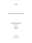
Executive Summary
Solar Powered Smart Blind (SPSB) is an autonomous, self-sustaining window blind
system. The SPBS system will automatically adjust the amount of the light that gets through
depending on a user preference while operating solely on solar power. The reason for the
construction of the SPSB system is to minimize the user interaction with blinds, therefore,
increase living comforts. There is a profitable market for automated window blinds. Potential
users for the Solar Powered Smart Blind system include senior citizens, the disabled, individuals
who are willing to adopt environment-friendly smart devices, and home automation enthusiasts.
The finalized SPSB prototype will consist of four photo sensors, stepper motor for controlling
the blind, Arduino microcontroller, and a user interface device. The photo sensor will transmit
information to the Arduino microcontroller, which will then interpret the incoming data and send
necessary control signals to the stepper motor to adjust the blinds. The time, date, room
temperature, and current user selected mode will be displayed on a Liquid-Crystal Display
(LCD) that is integrated into the user interface device. The SPSB system will incorporate powersaving algorithms to guarantee low power consumption. The total cost of the Solar Powered
Smart Blind system will be $72,020, with $168 spent on materials, $46,700 spent on design and
labor, and $25,000 spent on marketing. The suggested retail price of the finished product will be
at $175. The working Solar Powered Smart Blind system was successfully built, tested, and
demonstrated on the date of April 22, 2009.
3AM (ECE4007L04)
ii
Solar Powered Smart Blind
1.
INTRODUCTION
1.1
Objective
The purpose of the Solar Powered Smart Blind (SPSB) system is to provide convenient,
automated control of the amount of sunlight that is let through depending on the time of the day
and the light intensity. Utilizing solar power to sustain its operation via batteries, the system will
also incorporate digital displays of time and temperature. The SPSB system is the integration of
modern electronic control circuitry with ordinary window blind sold in department stores and
furniture outlets. The overall emphasis of the SPSB system is to provide user friendly home
electronics and appliances.
1.2
Motivation
Energy consumption is an enormous concern in the 21st century. The SPSB system can
provide convenience while using energy that comes directly from the sun. It is particularly
complimentary to people with limited mobility such as the disabled and senior citizens. Although
the system will be more expensive than the currently available blinds, there will still be a
profitable market for the product within the middle and upper class. If a device is within
purchasing power, people are willing to incur a higher cost so that they may avoid performing
trivial acts, in this case, turning the blinds every day. Examples of this tendency can be
commonly seen in the household from dishwashers to automated vacuuming robot. The working
SPSB system prototype is an innovative approach to an existing product that improves comfort
living style.
1.3
Background
Both electric and ordinary window blinds are available for purchase through the internet
and retail stores. Manually-adjusted window blinds have prices as low as $20 while electric
blinds range from $50 to $300. The most sophisticated version on the market incorporates
stepper motors that are controlled remotely to turn the blinds [1]. Batteries are required to power
the motors as well as the remote; therefore, battery replacement is necessary. There are also noncommercialized smart blinds constructed by individuals who are interested in the topic. One
particular prototype relied on four photo-detectors to determine the sun light intensity and adjusts
the angle of the blinds accordingly [2]. Other feasible approaches to implement a smart blind
3AM (ECE4007L04)
1
system include tracking the angle of the sun and voice-recognition. However, prototypes
operating under either of these principles have not been constructed [3].
None of the blind systems mentioned above is fully automatic. Although the remotecontrolled blinds are more convenient than the non-electric blinds, they still require the user to
give an input. The light-sensitive blind may be able to regulate light passage during the day, but
the users, nonetheless, need to manually close the blind at night time. In addition, all the electric
blinds introduced thus far do not have self-sustaining capability, as they depend on external
power or batteries to operate.
2.
PROJECT DESCRIPTION AND GOALS
Window blinds in homes have to be manually adjusted throughout the day to account for
changes from outside luminescence and temperature conditions. Solar Powered Smart Blind is a
microcontroller-embedded system that automatically adjusts itself in real time to account for
variations between indoor and outdoor luminescence conditions. The automation of the SPSB
system is accomplished by making use of photo-sensors integrated into the blinds. The power
supply for the system is recharged with solar panels attached to the window to capture maximum
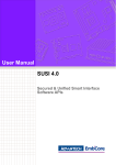
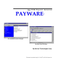
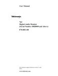
sunlight. A detailed depiction of the finished SPSB system prototype can be seen in Figure 1.
Figure 1. Component integrated SPSB system prototype.
3AM (ECE4007L04)
2
The goal of the SPSB system is to fully automate the process of adjusting window blinds
throughout the day based on a user provided input mode. SPSB adopters should be able to select
a luminescence intensity level from a combination of directional buttons and push buttons that
serves as a user input interface. Marketable consumers include senior citizens, disabled people,
home automation enthusiasts, and individuals who are willing to adopt environment-friendly
smart devices. The SPSB system was designed with the following goals:
•
Product price will be around $175
•
Energy efficient
•
Auto adjust based on user input parameters
•
Environment-friendly
•
Solar rechargeable
•
Easy installation
•
Manual override
•
Fabricate a working prototype by early April 2009
With careful planning and organization, the working SPSB system prototype meets all
the listed goals with the exception of easy installation. The working SPSB system requires heavy
technical background for installation in homes; with that note, the initial proposed plan to sell as
a standalone device would not be possible. The SPSB system would have to be sold with a
service plan included for installation.
3.
TECHNICIAL SPECIFICATIONS
Sensor Data Processing System
The designed prototype was fully implemented using the Arduino Duemilanove
microcontroller and provide easy integration for many components. The Arduino Duemilanove
microcontroller is an open-source electronics prototyping platform based on flexible, easy-to-use
hardware and software, used to process incoming sensor data. The microcontroller contains a
16MHz crystal oscillator and an ATmega168 chip on board with 14 digital I/O pins, six of which
can be used as PWM (Pulse Width Modulation) outputs [4]. The multichannel inputs and outputs
on the Arduino allow processing of several sensors simultaneously, which is an important part
for cross-algorithm. A further hardware specification of the Arduino board is provided below in
Table 1.
3AM (ECE4007L04)
3
Table 1 – Arduino Duemilanove Microcontroller
Model
Brand
Series
Specifications
Microcontroller
Operating Voltage
Input Voltage (recommended)
Input Voltage (limits)
Digital I/O Pins
Analog Input Pins
DC Current per I/O Pin
DC Current for 3.3V Pin
Flash Memory
SRAM
EEPROM
Clock Speed
Arduino
Duemilanove
ATmega168
5V
7-12V
6-20V
14 Pins
6 pins provide PWM output
6
40 mA
50 mA
16 KB
2 KB used by bootloader
1 KB
512 Bytes
16 MHz
User Interface (Input / Output)
The original user controls designed for the SPSB system included light intensity mode
select, manual override, window blind open/close button, and a LCD display for data
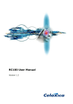
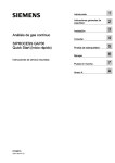
representation. The originally planned user interface device and the actual designed device can
be seen in Figure 2. The functionalities of button and dials successfully transmitted to the
Arduino microcontroller for processing.
The mounting mechanics for the interface box was eliminated for the prototype to
improve the demonstration of the product. Figure 2 also shows the temperature reading for the
room done with a DS1621 I2C chip that is mounted on the outside of the user control device for
accurate temperature sensing of the room. Table 2 describes the button functions of the interface
device. The button functionalities for the interface box were fully integrated using push buttons,
but the rotary dial was removed for the difficulty it provided in the construction of the interface
box.
3AM (ECE4007L04)
4
02/14/2009
12:00 AM
Indoor Temp:
27 C = 68 F
Mode: Bright
DS1621
Temp
IC
Manual
Overrid
Mode
Select
Figure 2. Originally planned interface box (top) and actual designed interface box (bottom).
Table 2 – User Interface Device
Controls
Function
Mode Select (Initially Proposed)
Selects brightness mode
Manual Override
Overrides the microcontroller’s
automatic mode for user
adjustments
Arrow Keys
Tilts the blinds up and down
for the user
DS1621 Temp IC
Mounted outside the box for
sensing room temperature
LCD Display
Displays various information
for the user to see
3AM (ECE4007L04)
5
Physical Weight & Size
The four photo-resistors were initially placed on the strings of the blind in a vertical line
formation, but the finished prototype utilizes the photoresistors on the mounting rail of the blind.
The wiring required for connections of various sensors and components is done with RJ-45 cable
to achieve a clean installation of the SPSB system. Ideally, the solar smart blinds, consisting of
stepper motor and a user interface device effectively function on any house hold windows.
However, due to the wide diversity of window arrangements, shapes, and sizes, the testing of the
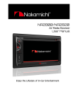
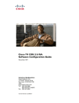
SPSB system was confined to a small standard window size. A 23” X 64” standard household
blind was utilized and the entire prototype weighs around 10 lbs. as shown in Figure 3.
Figure 3. Standard household blind dimension (23” X 64”) and weight (~10 lbs.).
Software & Power Supply
The software required for controlling the stepper motor, reading sensors, and
communicating with I2C chips were written in C/C++ within the Arduino version 0012
integrated development environments (IDE). The open-source Arduino environment makes it
easy to write code and upload it to the I/O board. It runs on Windows, Mac OS X, and Linux.
The environment is written in Java and based on Processing, AVR-GCC, and other open source
software [4].
Minimization of power consumption was necessary since the SPSB system did not
require high operational power supply. Therefore, various sleep modes were not utilized. The
3AM (ECE4007L04)
6
rechargeable batteries used in powering of the SPSB system included 12V as listed in Table 3.
The recharging process was achieved during the day time, but the system also consume solar
power when needed [5]. The SPSB system is operational during the day time and remained in
power down state during the night time to limit power consumption. The real-time clock (RTC)
and the photoresistor readings were used to check the time to power off the SPSB system during
night time.
Table 3 – Rechargeable Battery Specification
Voltage Requirement
12 Volts
Full Charging Time
mA Hour Rating
Chargeable Quantity
Memory Effect
3 Hours
230mAh
~ 1000 times
No memory effect
Motorized & Manual Adjustments
The software written for the solar blind system was able to operate autonomously, and it
was able to take in user manual controls. Signals from the Arduino microcontroller were sent to
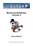
the stepper motor control driver to adjust the blinds. Initially, to achieve physical aesthetics, the
stepper motor was to be mounted inside the frame of the blind, but with limited time, a design
change was implemented to complete a working prototype by the end of April. Original stepper
motor mounting plan and the final mounting arrangement are illustrated in Figure 4.
Stepper Motor
Figure 4. Initial stepper motor mounting (left) and designed stepper motor mounting (right).
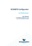
A 5V stepper motor planned to be used to control the physical movements of the SPSB
system, but the actual stepper motor used in the prototype is illustrated in Figure 5.
Specifications for the used stepper motor are described as follow:
•
Manufactured by Mitsumi
3AM (ECE4007L04)
7
•
Operates on 12VDC
•
2 phase bi-polar / quadrature motor
•
7.5 degree step angle
•
Motor includes a printed copy of a simple driver circuit schematic
•
Knurled shaft dimensions: .3" L x .06" Diameter
•
Motor dimensions (not including shaft): .8" Dia. x .68" H
•
4 lead connection (2 leads connected together) terminated with a 4 pin female plug
•
2 3/4" long leads
Figure 5. 12 VDC Symbol Technologies stepper motor.
Performance & Operation
The performance and operation of the SPSB system prototype are the following:
•
Recharge the on board batteries during the day with solar panels
•
Blinds remain shut during night time
•
Blinds automatically open in the morning
•
Manual override can be performed by the user
•
Blinds auto adjust based on user input mode
•
LCD displays date, time, room temperature, and current user select mode
•
The blinds, user interface device, wiring, sensors, and solar recharging
components will be a package that is available to the consumers
•
4.
I2C component integration
Design Approach and Details
The Brain – ATmega168 Microcontroller
The information processing of the SPSB system is handled by a small, open-source
Arduino Duemilanove microcontroller, as shown in Figure 6. This Arduino board serves as the
3AM (ECE4007L04)
8
main controller for the SPSB system. The microcontroller is programmable in C/C++ and has the
capability to import/export data to Matlab. The microcontroller is enclosed in a transparent
plastic enclosure.
Figure 6. Arduino Duemilanove microcontroller and the board component layout.
The Automation – Blind Control Algorithm
The key feature of the SPSB system is to automatically adjust its orientation to maintain
and control a room’s light intensity. Photo-sensors generate voltage signals corresponding to
the indoor and outdoor light intensities, and the microcontroller transforms the voltages to digital
values ranging 0-1024. Every time the mode is switched to automatic, the system would detect if
it is day or night. If the average voltage for the outdoor light intensities went below a threshold
value of 200, the system would detect night and automatically close the blinds. If daytime is
detected, the SPSB system would turn the blinds from one extreme to the other extreme and
position the blinds at the point maximum indoor luminescence is detected. Every five minute
delays, the system would check the light intensity at its current position, 15 degrees above, and
15 degrees below and position the blinds to the position with maximum indoor luminescence.
The Energy Source – Solar Recharging Circuit
There is a 12V DC input provided by NiCad rechargeable batteries. The batteries are
recharge via solar cell collectors, through a passive circuit that protect it from over charge. The
diodes act as a switch that open the charging circuit when the battery is full. The recharging of
12V batteries pack is done during the daytime with a custom solar recharging circuit. Various
solar recharging circuits were examined and tested to implement in the final design part of the
power source. The final used solar recharging circuit is shown in Figure 7.
3AM (ECE4007L04)
9
Figure 7. Solar recharging implementation circuit.
The Integration – The I2C LCD Display
The SPSB system ues a text based LCD control module that allows the users to select
various modes. LCD screen was able to display and accept user input such as time, alarm clock,
temperature, and light intensity mode. The indoor temperature sensors, Real-Time Clock (RTC),
and text based LCD display all communicated on multi-master serial computer bus, I2C invented
by Philips. The I2C components received and transmitted data with the Arduino microcontroller
using only two bi-directional open-drain lines, Serial Data (SDA) and Serial Clock (SCL). With
the two bi-directional clock and data lines, multiple number integrated circuit devices can be
connected and utilized with I2C communication protocol. (See Figure 8)
Figure 8. I2C device communication protocol connections and LCD diplay.
3AM (ECE4007L04)
10
4.2
Codes and Standards
The finished SPSB system prototype abides by the following codes and standards
described below. The most important standard and code followed during the design project were
the IEEE Standard 1375 and IEEE Standard 1349. The DC power supply and the stepper motor
current draw was a major concern for the prototype.
The Arduino microcontroller for this project is based on the Atmel ATmega168, which
contains a 16KB programmable flash memory, 1KB SRAM, 512 Bytes EEPROM, 8 Channel 10bit A/D-converter (TQFP/MLF), and wire on-chip debug system. This AVR chip is certified by
the American National Standards Institute (ANSI). The Arduino programming language C/C++
also satisfied ANSI standards [6].
The SPSB system is integrated with multitude of electronics: stepping motor,
photovoltaic charging circuitry, lithium ions/polymers battery. The stepper motor for the SPSB
system was implemented using the IEEE Standard 1349. The standard indicates general-purpose
enclosure for the motor and precautions against excessive surface temperatures. The SPSB
system was constructed to minimize sparking of rotor bars and enclosure joints [7].
To be able to sell the SPSB system on the U.S. consumer market, the SPSB system must
comply with the IEEE Standard 1375. The standard specifically states that DC power systems
must minimize the risk of equipment damage during electrically faulted conditions, limit the
number and duration of the battery system service interruptions as a result of electrically faulted
conditions [8].
4.3
Constraints, Alternatives, and Tradeoffs
The SPSB prototype does not contain hazardous materials to the environment. The
system helps the user save energy by utilizing a solar power energy source. According to the Go
Green Initiative, the SPSB system reduces energy consumption (See Appendix A). By utilizing
solar powered energy source, a trade offs are the an inconsistent energy supply when there is no
sunlight; during stormy days, cloudy days, nights etc. However the system is design to address
that with rechargeable battery powered circuitry with DC input from regular outlet AC power
source. Care must be taken whenever operating equipment that requires electrical power.
Constraints
•
Complexity of wireless communication
•
Better user interface requires more energy consumption
3AM (ECE4007L04)
11
Alternatives
•
AC power source adds carbon waste
•
Remote controlled blinds requires wireless communication & user inputs
•
Functionality of roll up blinds is simplistic
The AC power source was utilized for the final demonstration to ensure the correct
operation of the SPSB system and using the AC power source violated our initial design
objective, but with a constant power supply, the SPSB system was fully demonstrated with out
any problems.
Tradeoffs
5.
•
Reliable power source from an AC outlet
•
Reduced cost of manufacturing
•
Engineering simplicity
Schedule, Tasks, and Milestones
The project was divided into eight specific tasks shown in Table 4. Every task was
collectively completed by at least two group members. Each group member was given four tasks,
except the team leader who was fully involved in every process of the entire design tasks. The
entire process of project completion was scheduled into five milestones. The corresponding tasks
and the allotted time associated with each milestone are shown in the Gantt chart in Figure 9.
The entire design team was successful at following the drawn task schedule.
Table 4. Individual Group Member Tasks
Tasks
Solar
Charging
Circuit
Photo-detector
Implementation
Kevin
Vo
Lai Li
X
X
X
Marco
Herrera
Naing
Oo
Motor
Control
X
X
X
X
Microcontroller
Programming
Website and
Documentation
I2 C
Components
Testing
X
X
X
X
X
X
Prototype
Construction
X
X
X
X
X
X
X
X
Detailed descriptions of the important tasks in Figure 9 are as follow:
•
Research and Order Parts involves selecting and buying components.
3AM (ECE4007L04)
12
•
Component Implementation includes attachment of the solar panel to batteryrecharging circuit and evaluating the photo-detector sensitivity.
•
Microcontroller Programming covered I2C protocols for communication with RTC
and temperature sensor, voltage signal outputs for motor control, information display
on the LCD, automation algorithms, and a power-saving sleep mode.
•
Structure Fabrication has two parts: construction of a window frame and the
integration of all the individual components.
•
Testing and Optimization encompasses discovering unexpected problems with the
SPSB system and solving these problems.
3AM (ECE4007L04)
13
Figure 9. Gantt chart for project schedule.
3AM (ECE4007L04)
14
6.
PROJECT DEMONSTRATION
The final project demonstration took place in a campus building at 10:30 AM. The SPSB
system, as shown in Figure 10, was mounted on a window that has maximum sunlight intensity
projected. The demonstration included two parts: a live demonstration and a recorded video
demonstration.
Figure 10. The SPSB system installed and demonstrated on April 22, 2009.
Live Demonstration
A successful demonstration was concluded with the SPSB system automatically adjusting
the blinds to an angle where maximum sunlight enters the building room.
Recorded Video Demonstration
A recording of a calibration mode of the solar smart blind system was shown during the
presentation on April 22, 2009.
7.
MARKETING AND COST ANALYSIS
7.1
Marketing Analysis
The SPSB product will be available to every person, but the main goal is primarily aimed
at two distinct groups: handicapped/elderly and home automation enthusiasts. The self
maintained product comes with built in modes that continuously adjust the blinds autonomously.
3AM (ECE4007L04)
15
The handicapped and elderly may benefit from these smart blinds, since a great majority of these
individuals are unable to manually adjust the blinds. The home automation enthusiasts will
enjoy this additional device to their home.
There are no available products in the market that are identical to the SPSB system. The
closest competitive product is not autonomous. The Hunter Douglas PowerRise Honeycomb
Cellular Shades is one of the competitive blinds. These blinds require the user to adjust the
blinds with a remote control. The competitive blinds system is battery powered and priced at
$100 or more [9]. Other competitive products work similarly, requiring the user to adjust the
blinds with various user interfaces (control box, remote control). The SPSB system contains
manual operation in addition to automatic operation. Solar panels charge batteries, which is the
power source for the system. These features are not integrated into any competitive product.
7.2
Cost Analysis
The overall cost analysis for the SPSB system did not change from what was originally
calculated in the initial proposal. The development, design, and a five-year marketing plan of the
SPSB system is estimated to cost $72,020. Table 5 shows the material, design, labor, and
marketing costs.
Table 5 – Total Project Cost
Material Cost
$168
Design/Labor Cost
$46,700
Marketing (5 Years)
Total Project Cost
$25,000
$71,868
The working product is to be mass produced and is expected to be sold at major home
hardware stores. Material cost is expected to be reduced from $168 to $150 per SPSB system if
parts and components are purchased in quantities of thousands. The labor cost to assemble and
test the product by a third party is expected to be $10 per SPSB system. The projected profit per
system is $15. The resulting retail price is $175. Over a period of five years, it is expected to sell
40,000 units, yielding a profit of over half a million dollars. The profit will cover the total
project design cost with over $500,000 left for design improvements. Individual detailed costs
are located in Appendix B.
3AM (ECE4007L04)
16
8.
SUMMARY
The design group was successful at designing, testing, and demonstration of the SPSB
system by the end of April 2009 as initially promised. The prototype was fully designed with all
the components and technologies promised in the initial proposal with the exception of the
stepper motor mounting and the power management system. The working algorithm and code for
the SPSB system is available in the Appendix C. In the future, the SPSB system components
and subsystem could be fully implemented into the frame of the blind and the product could be
sold with the window. Furthermore, the solar cells used in the prototype could be replaced with
high density solar cells and fully integrated on the individual blinds of the SPSB system to
increase photon collection efficiency. With current improvement in the production of solar cells,
the SPSB system could also be implemented with spray on solar cells that are currently in
development. The sprays on solar cells are plastic material manufactured with nanotechnology
and contain the first solar cells able to harness the sun's invisible, infrared rays [17]. The spray
on solar cell breakthrough has theorists to predict that plastic solar cells could one day become
five times more efficient than current solar cell technology [17]. The spray on article is available
in the Appendix D.
3AM (ECE4007L04)
17
9.
REFERENCES
[1]
Electrical blinds, by K. Masanori. (1989, Nov. 07). Patent 4878528 [Online]. Available:
http://www.freepatentsonline.com/4878528.html?query=blinds&stemming=on
[2]
A. Rhuberg, et al. Auto Blinds [Online]. Available:
http://lims.mech.northwestern.edu/~design/mechatronics/2000/Team13/index.html
[3]
Junglefish. (2005, Aug. 29). Smart Window Blinds [Online]. Available:
http://www.halfbakery.com/idea/Smart_20Window_20Blinds#1125430916
[4]
Arduino, “Arduino Duemilanove,” [Company Website], [cited 2009 Jan 23], Available
HTTP: http://www.arduino.cc/
[5]
Amazon Inc., “Sony 2500 mAh AA Rechargeable Nimh Batteries”, [Company Website],
[cited 2009 Feb 2], Available HTTP: http://www.amazon.com/Sony-2500-RechargeableBatteries-4-pack/dp/B0007LBVHI
[6]
Orangutan-Lib, “Orangutan Hardware”, [Company Website], [cited 2009 Jan. 31],
Available HTTP: http://orangutan-lib.sourceforge.net/hardware.shtml
[7]
IEEE Guide for the Application of Electric Motors in Class I, IEEE Standard 1349, 2001
[8]
IEEE guide for the protection of stationary battery systems, IEEE Standard 1375, 1998
[9]
Your Blinds, Inc., “Motorized Honeycomb Cellular Shades,” [Company Website], [Cited
2009 Jan 31], Available HTTP:
http://www.yourblinds.com/products/cellular/hunter_douglas/hdcs0110.asp
[10]
Modern Device, “Arduino Duemilanove,” [Company Website], [Cited 2009 Jan 31],
Available HTTP: http://www.moderndevice.com/diecimila.shtml
[11]
Homer TLC, Inc. “designview 34 In. x 64 In. White 2 In. Grandwood Blind,” [Company
Website], [Cited 2009 Jan 31], Available HTTP:
http://www.homedepot.com/webapp/wcs/stores/servlet/ProductDisplay?storeId=10051&l
angId=-1&catalogId=10053&productId=100048203&categoryID=501387
3AM (ECE4007L04)
18
[12]
Maxim Integrated Products, “DS1621,” [Company Website], [Cited 2009 Jan 31],
Available HTTP: http://www.maxim-ic.com/quick_view2.cfm/qv_pk/2737/t/al
[13]
Maxim Integrated Products, “DS1307,” [Company Website], [Cited 2009 Jan 31],
Available HTTP: http://www.maxim-ic.com/quick_view2.cfm/qv_pk/2688
[14]
RadioShack Corp., “CdS Photoresistors (5-Pack),” [Company Website], [Cited 2009 Jan
31], Available HTTP: http://www.radioshack.com/product/index.jsp?productId=2062590
[15]
Fun Gizmos, “16x2 Character LCD - Serial I2C/SPI/RS232-TTL,” [Company Website],
[Cited 2009 Jan 31], Available HTTP:
http://store.fungizmos.com/index.php?main_page=product_info&cPath=70&products_id
=210&zenid=a21a906337dc919ae237bf64a39780dc
[16]
Gaebler Ventures, “National TV Spots: Costs of Advertising on Television,” [Company
Website], [Cited 2009 Jan 31], Available HTTP: http://www.gaebler.com/National-TVSpot-Ad-Costs.htm
[17]
Gaebler Ventures, “National TV Spots: Costs of Advertising on Television,” [Company
Website], [Cited 2009 Jan 31], Available HTTP:
http://news.nationalgeographic.com/news/2005/01/0114_050114_solarplastic.html
3AM (ECE4007L04)
19
APPENDIX A – GO GREEN INITIATIVE PRINCIPLES
http://gogreeninitiative.org/index.php
The Five Principles
The Go Green Initiative comprises five principles that provide the
framework for teaching environmentally responsible behaviors on
campus. These principles serve as a guide for schools to evaluate
every aspect of their environmental impact. Schools may implement
as few as three principles in creating their own unique programs
designed to address local concerns. (For a detailed discussion of the
five principles of the GGI, see the Go Green Planning Guide).
1. Generate compost. This is nature's way of recycling. Through basic and worm
composting programs, children learn about ecology, biology and waste reduction.
2. Recycle everything that cannot be reused and purchase items that can be recycled. With
fast shrinking landfill space and diminishing natural resources, recycling has never been
more important. Recycling items such as paper, plastic, aluminum and ink cartridges
reduces toxic greenhouse gas emissions and conserves energy. Manage E-waste by
finding creative solutions to divert obsolete computer parts, cell phones and other such
devices from the waste stream. Schools that recycle provide much-needed materials to
manufacturers who produce recycled products.
3. Educate students, teachers and parents on environmentally-responsible behavior. When
students, teachers and parents work together to make their schools environmentally
friendly, they are more likely to take the same behaviors into their off campus lives. Our
goal is to create environmentally-responsible school communities throughout the nation
and across the globe.
4. Evaluate the environmental impact of every activity. Identify products and practices that
could threaten the health of children and the world around them. Consider improving the
campus environment with activities such as eliminating excessive energy consumption;
evaluating the toxicity of pesticides used in classrooms and on playgrounds; improving
outdoor air quality through increased carpooling efforts; and working to improve indoor
air quality.
5. Nationalize the principles of responsible paper consumption. Consider purchasing post
consumer recycled paper and office products. Use technology to communicate
electronically as much as possible. Seek ways to provide Internet access to all school
families.
3AM (ECE4007L04)
20
APPENDIX B – DETAILED COST ANALYSIS
Component Cost
Parts
Unit Price
Quantity
Cost
Shipping
Arduino Microcontroller [10]
$30
1
$30
$2
Blinds [11]
$5
1
$5
$0
DS1621 Temperature Sensor [12]
$2
1
$2
$2
DS1307 Real Time Clock [13]
$2
1
$2
$2
Photo-resistor, Pack of 5 [14]
$2
1
$2
$0
Stepper Motor w/ Driver
$25
1
$25
$5
Solar Panels
$5
4
$20
$5
Rechargeable Batteries(24)
$15
1
$15
$0
16x2 Character LCD - Serial I2C/SPI/RS232-TTL [15]
$24
1
$24
$2
Cat5e Ethernet Wire
$20
1
$20
$0
Wires, Buttons, Various Sizes and Lengths
$5
1
$5
$0
$150
$18
TOTAL PARTS COST
Design & Labor Cost
3AM (ECE4007L04)
21
Design
Rate
Hours
Persons Involved
Cost
Lectures and Meetings
$50/hr
136
All 4
$27,200
Research/Design/Reports/Presentations $50/hr
50
All 4
$10,000
Programming
$75/hr
20
Naing, Marco
$3,000
Assembling Prototype
$75/hr
30
Lai, Kevin
$4,500
Testing/Troubleshooting
$50/hr
20
Naing, Marco
$2,000
Total Design Cost
$46,700
Marketing Cost
Advertisement Medium
Cost
Television Commercials [16]
$3,000
Newspaper Adds
$1,000
Internet
$500
Special Event
$500
Total Marketing Cost Per Year
$5,000
3AM (ECE4007L04)
22
APPENDIX C – SOLAR SMART BLIND SYSTEM CODE
//Solar Powered Smart Blinds System
//L-04, DK-1, Professor Keezer
//Marco Herrera, Lai Li, Naing Oo, Kevin Long Vo
//4-22-09
//Design Project Code Revision 3; dk1_project_r3.c
//AT START UP, IT CALIBRATES, THEN GOES TO MANUAL MODE...NEED TO PRESS RIGHT CIRCLE
PUSHBUTTON TO SWITCH BETWEEN MODES.
//IN MANUAL MODE, YOU CAN ADJUST BLINDS WITH UP AND DOWN PUSHBUTTONS
//IN AUTOMATIC MODE, BLINDS ADJUST AUTOMATICALLY
//PRESSING LEFT CIRCLE PUSHBUTTON ALLOWS YOU TO ENTER/EXIT TIME EDIT MODE REGARDLESS OF
OPERATIONAL MODE
//YOU CAN EDIT TIME IN TIME MODE WITH LEFT, RIGHT, UP, AND DOWN PUSHBUTTONS
//ONLY IN AUTOMATIC MODE IS THAT THE LCD SHUTS OFF AFTER A TIME LAPSE OF NO PUSHBUTTON
MOVEMENTS
#include <Wire.h>
//I2C ADDRESS DEFINITIONS
#define tempSensor_addr 0x90 >> 1
#define LCD_addr 0x50 >> 1
#define RTC_addr 0xD0 >> 1
char LCD_LINE1[17] = " / /
";
char LCD_LINE2[17] = " : M
F";
char LCD_LINE3[17] = "MM/DD/YY DAY A/M";
char LCD_LINE4[17] = "HH:MM AM XX F";
char LCD_LINE5[17] = "SET DATE & TIME ";
char LCD_LINE6[17] = "
";
char LCD_LINE7[17] = " SOLAR POWER ";
char LCD_LINE8[17] = " SMART BLINDS ";
char LCD_LINE9[17] = "DONE SETING TIME";
char LCD_LINE10[17] = "
";
// RTC CLOCK REGISTERS
#define R_SECS 0
#define R_MINS 1
#define R_HRS
2
#define R_WKDAY 3
#define R_DATE 4
#define R_MONTH 5
#define R_YEAR 6
#define R_SQW
7
//RTC VARIABLES
3AM (ECE4007L04)
23
byte second = 30;
byte minute = 39;
byte hour = 16;
byte wkDay = 3;
byte day = 21;
byte month = 4;
byte year = 9;
byte ctrl = 0x00;
// default=> 3:15:30AM 20 APRIL 2009
//TEMPORARY VARIABLES
byte temp1;
int mode = 1;
//0=>Automatic 1=>Manual
int temp = 0;
//TIME EDIT VARIABLES
int setTimeCounter = 0;
int setTimeTemp1 = 0;
int setTimeTemp2 = 0;
int timeMode = 0;
//MANUAL MODE VARIABLE
int manModeTemp1 = 0;
//AUTOMATIC MODE VARIABLES
int autModeTemp1 = 0;
int autoCounter = 0;
int autoStep = 0;
int autoNewVal = 0;
int autoOldVal = 0;
int autoVal0 = 0;
int autoVal1 = 0;
int autoVal2 = 0;
int autoStep1 = 0;
int autoStep2 = 0;
int delayMax = 1*600; //delay between checkings, first value is the minutes
int delayCounter = 0;
//STEPPER MOTOR
int smStep = 3; //stepper motor step
int smDir = 4; //stepper motor direction
int smDelay = 1200;
int stepCounter = 0;
int smPosition = 0;
int smUpLimit = 0;
int smDownLimit = 0;
int smStepRange = 0;
//LCD & LED
int outLCD = 7; //LCD turn on
int outLED = 2; //LED turn on
int LCDon = 0;
3AM (ECE4007L04)
24
//BLINDS CLOSED SENSORS
int inCloseA = 6; //detects if blinds closed one way
int inCloseB = 5; //detects if blinds closed one way
//BLINDS CLOSED VALUE VARIABLES
int iA = 0;
//value variable for closeA
int iB = 0;
//value variable for closeB
//PHOTORESISTORS ANALOG INPUTS
int inSensor0 = 0; //select the input pin for the sensor0
int inSensor1 = 1; //select the input pin for the sensor1
int inSensor2 = 2; //select the input pin for the sensor2
int inSensor3 = 3; //select the input pin for the sensor3
//PHOTORESISTORS VALUE VARIABLES
int iVal0 = 0; //variable to store the value coming from the sensor0
int iVal1 = 0; //variable to store the value coming from the sensor1
int iVal2 = 0; //variable to store the value coming from the sensor2
int iVal3 = 0; //variable to store the value coming from the sensor3
int iFrontAvg = 0;
//variable to store average from front sensor values
int iBackAvg = 0;
//variable to store average from back sensor values
//PUSHBUTTONS
int pbUp = 13; //pushbutton up
int pbDown = 12; //pushbutton down
int pbLeft = 11; //pushbutton left
int pbRight = 10; //pushbutton right
int pbMode = 9; //pushbutton mode
int pbTime = 8; //pushbutton time
//PUSHBUTTON VALUE VARIABLES
int iUp = 0;
//variable to store the new value read from the pushbutton up
int iDown = 0; //variable to store the new value read from the pushbutton down
int iLeft = 0; //variable to store the new value read from the pushbutton left
int iRight = 0; //variable to store the new value read from the pushbutton right
int iMode = 0; //variable to store the new value read from the pushbutton mode
int iTime = 0; //variable to store the new value read from the pushbutton time
void setup() {
//setup function
//START OF I2C COMMUNICATION
Wire.begin();
//INSERTION OF DEGREE SYMBOL IN LCD STRINGS
LCD_LINE4[14] = 0xdf;
LCD_LINE2[14] = 0xdf;
//ALL INPUTS/OUTPUTS ARE INITIALIZED
//PUSHBUTTONS
pinMode(pbUp, INPUT);
pinMode(pbDown, INPUT);
3AM (ECE4007L04)
25
pinMode(pbLeft, INPUT);
pinMode(pbRight, INPUT);
pinMode(pbMode, INPUT);
pinMode(pbTime, INPUT);
//BLINDS CLOSED
pinMode(inCloseA, INPUT);
pinMode(inCloseB, INPUT);
//LCD, LED, STEPPER MOTOR OUTPUTS
pinMode(smStep, OUTPUT);
pinMode(smDir, OUTPUT);
pinMode(outLCD, OUTPUT);
pinMode(outLED, OUTPUT);
//START OF SETUP
LCD(1);
//LCD is turned on
calibrate();
//the system is calibrated
}
void loop() {
//loop function
if(mode == 0) automatic();
//AUTOMATIC MODE
if(mode == 1) manual();
//MANUAL MODE
}
void automatic()
//manual mode, the blinds open/close all day as specified; pushbuttons
are constantly being read
{
getClock();
LCDupdate();
autoSet();
delayCounter = 0;
while(mode == 0)
{
autModeTemp1 = readPB();
if((autModeTemp1 >= 1) && (autModeTemp1 <= 4) && (LCDon == 0))
{
LCD(1);
delayCounter = 0;
}
else if((autModeTemp1 == 6) && (LCDon == 1)) setTime();
else if((autModeTemp1 == 5) && (LCDon == 1)) mode = 1;
else
{
if(delayCounter >= delayMax)
{
delayCounter = 0;
autoAdjust();
3AM (ECE4007L04)
26
}
//delayCounter += 1;
delay(100);
if(LCDon)
{
getClock();
LCDupdate();
}
}
delayCounter += 1;
}
}
void manual()
//manual mode, user can move blinds with up/down pushbuttons;
pushbuttons are constantly being read
{
while(mode)
{
manModeTemp1 = readPBman();
if(manModeTemp1 == 1)
{
blindUp();
}
else if(manModeTemp1 == 2)
{
blindDown();
}
else if(manModeTemp1 == 5) mode = 0;
else if(manModeTemp1 == 6) setTime();
else
{
delay(100);
getClock();
LCDupdate();
}
}
}
void setTime()
being read
{
delay(100);
LCDdisplay(1,5);
LCDdisplay(2,6);
delay(500);
timeMode = 1;
while(timeMode)
{
3AM (ECE4007L04)
//sets the time and date for the system; pushbuttons are constantly
27
delay(100);
setTimeTemp1 = readPB();
if((setTimeCounter == 0) && ~((setTimeTemp1 == 3) || (setTimeTemp1 == 4) ||
(setTimeTemp1 == 6)))
{
if(setTimeTemp1 == 1)
{
if(month == 12) month = 1;
else month +=1;
}
if(setTimeTemp1 == 2)
{
if(month == 1) month = 12;
else month -=1;
}
LCDupdate();
}
if((setTimeCounter == 1) && ~((setTimeTemp1 == 3) || (setTimeTemp1 == 4) ||
(setTimeTemp1 == 6)))
{
if(setTimeTemp1 == 1)
{
if(day == 31) day = 1;
else day +=1;
}
if(setTimeTemp1 == 2)
{
if(day == 1) day = 31;
else day -=1;
}
LCDupdate();
}
if((setTimeCounter == 2) && ~((setTimeTemp1 == 3) || (setTimeTemp1 == 4) ||
(setTimeTemp1 == 6)))
{
if(setTimeTemp1 == 1)
{
if(year == 99) year = 0;
else year +=1;
}
if(setTimeTemp1 == 2)
{
if(year == 0) year = 99;
else year -=1;
}
LCDupdate();
}
3AM (ECE4007L04)
28
if((setTimeCounter == 3) && ~((setTimeTemp1 == 3) || (setTimeTemp1 == 4) ||
(setTimeTemp1 == 6)))
{
if(setTimeTemp1 == 1)
{
if(wkDay == 7) wkDay = 1;
else wkDay +=1;
}
if(setTimeTemp1 == 2)
{
if(wkDay == 1) wkDay = 7;
else wkDay -=1;
}
LCDupdate();
}
if((setTimeCounter == 4) && ~((setTimeTemp1 == 3) || (setTimeTemp1 == 4) ||
(setTimeTemp1 == 6)))
{
if(setTimeTemp1 == 1)
{
if(hour == 23) hour = 0;
else hour +=1;
}
if(setTimeTemp1 == 2)
{
if(hour == 0) hour = 23;
else hour -=1;
}
LCDupdate();
}
if((setTimeCounter == 5) && ~((setTimeTemp1 == 3) || (setTimeTemp1 == 4) ||
(setTimeTemp1 == 6)))
{
if(setTimeTemp1 == 1)
{
if(minute == 59) minute = 0;
else minute +=1;
}
if(setTimeTemp1 == 2)
{
if(minute == 0) minute = 59;
else minute -=1;
}
}
if((setTimeTemp1 == 3) || (setTimeTemp1 == 4))
{
if(setTimeTemp1 == 3)
{
3AM (ECE4007L04)
29
if(setTimeCounter == 5) setTimeCounter = 0;
else setTimeCounter +=1;
}
if(setTimeTemp1 == 4)
{
if(setTimeCounter == 0) setTimeCounter = 5;
else setTimeCounter -=1;
}
}
if(setTimeTemp1 == 6) timeMode=0;
LCDupdate();
}
setClock();
delay(100);
LCDdisplay(1,9);
LCDdisplay(2,10);
delay(500);
}
void calibrate()
//calibrates the system to find the full range movement of the blind and leaves
the blind half way
{
readClose();
while((iA == LOW) && (iB == LOW))
{
smPosition +=10;
smUpLimit +=10;
stepping(10, 1);
readClose();
}
stepping(smPosition, 0);
smPosition = 0;
readClose();
while((iA == LOW) && (iB == LOW))
{
smPosition -=10;
smDownLimit -=10;
stepping(10, 0);
readClose();
}
blindHalf();
smStepRange = (smUpLimit - smDownLimit)/100;
smStepRange = smStepRange * 10;
}
void autoSet()
automatic mode
{
3AM (ECE4007L04)
//finds the position where maximum sunlight enters the room once in
30
stepPosition(smDownLimit);
readSensors();
autoStep = 0;
autoOldVal = iFrontAvg;
autoCounter = 1;
for(autoCounter; autoCounter <= 10; autoCounter++)
{
readSensors();
autoNewVal = iFrontAvg;
if(autoNewVal > autoOldVal)
{
autoStep = autoCounter;
autoOldVal = autoNewVal;
}
stepPosition((autoCounter*smStepRange) + smDownLimit);
}
stepPosition((autoStep*smStepRange) + smDownLimit);
}
void autoAdjust()
//constantly gradually adjusts the blinds if needed in automatice mode
{
readSensors();
autoVal0 = iFrontAvg;
autoStep1 = autoStep - 1;
autoStep2 = autoStep + 1;
stepPosition((autoStep1*smStepRange) + smDownLimit);
readSensors();
autoVal1 = iFrontAvg;
stepPosition((autoStep2*smStepRange) + smDownLimit);
readSensors();
autoVal2 = iFrontAvg;
if((autoVal1>autoVal0) && (autoVal1>autoVal2)) autoStep = autoStep1;
if((autoVal2>autoVal0) && (autoVal2>autoVal1)) autoStep = autoStep2;
stepPosition((autoStep*smStepRange) + smDownLimit);
}
void stepping(int steps, int dir) //moves the stepper motor specified steps in specified direction
{
if(dir == 1) digitalWrite(smDir, LOW);
if(dir == 0) digitalWrite(smDir, HIGH);
for(stepCounter = 0; stepCounter < steps; stepCounter++)
{
digitalWrite(smStep, LOW);
delayMicroseconds(smDelay);
digitalWrite(smStep, HIGH);
delayMicroseconds(smDelay);
}
}
3AM (ECE4007L04)
31
void stepPosition(int position)
//positions the blinds at a specific position
{
if(position > smPosition)
{
digitalWrite(smDir, LOW);
for(stepCounter = 0; stepCounter < (position-smPosition); stepCounter++)
{
digitalWrite(smStep, LOW);
delayMicroseconds(smDelay);
digitalWrite(smStep, HIGH);
delayMicroseconds(smDelay);
}
smPosition = position;
}
if(position < smPosition)
{
digitalWrite(smDir, HIGH);
for(stepCounter = 0; stepCounter < (smPosition-position); stepCounter++)
{
digitalWrite(smStep, LOW);
delayMicroseconds(smDelay);
digitalWrite(smStep, HIGH);
delayMicroseconds(smDelay);
}
smPosition = position;
}
}
void readSensors()
//reads the light sensors and stores the values
{
iVal0 = analogRead(inSensor0); // read the value from the sensor
iVal1 = analogRead(inSensor1); // read the value from the sensor
iVal2 = analogRead(inSensor2); // read the value from the sensor
iVal3 = analogRead(inSensor3); // read the value from the sensor
iFrontAvg = (iVal0 + iVal1)/2;
iBackAvg = (iVal2 + iVal3)/2;
}
int readPB()
//reads the pushbuttons for automatic and time edit modes
{
iUp = digitalRead(pbUp);
// read the value from pbUp
iDown = digitalRead(pbDown); // read the value from pbDown
iLeft = digitalRead(pbLeft); // read the value from pbLeft
iRight = digitalRead(pbRight); // read the value from pbRight
iMode = digitalRead(pbMode); // read the value from pbMode
iTime = digitalRead(pbTime); // read the value from pbTime
if(iUp == HIGH)
3AM (ECE4007L04)
32
{
while(iUp == HIGH)
{
iUp = digitalRead(pbUp);
}
return 1;
// read the value from pbUp
}
if(iDown == HIGH)
{
while(iDown == HIGH)
{
iDown = digitalRead(pbDown);
// read the value from pbUp
}
return 2;
}
if(iLeft == HIGH)
{
while(iLeft == HIGH)
{
iLeft = digitalRead(pbLeft);
// read the value from pbUp
}
return 3;
}
if(iRight == HIGH)
{
while(iRight == HIGH)
{
iRight = digitalRead(pbRight);
// read the value from pbUp
}
return 4;
}
if(iMode == HIGH)
{
while(iMode == HIGH)
{
iMode = digitalRead(pbMode);
// read the value from pbUp
}
return 5;
}
if(iTime == HIGH)
{
while(iTime == HIGH)
{
iTime = digitalRead(pbTime);
// read the value from pbUp
}
return 6;
}
return 0;
3AM (ECE4007L04)
33
}
int readPBman()
//reads the pushbuttons for manual mode
{
iUp = digitalRead(pbUp);
// read the value from pbUp
iDown = digitalRead(pbDown); // read the value from pbDown
iLeft = digitalRead(pbLeft); // read the value from pbLeft
iRight = digitalRead(pbRight); // read the value from pbRight
iMode = digitalRead(pbMode); // read the value from pbMode
iTime = digitalRead(pbTime); // read the value from pbTime
if(iUp == HIGH) return 1;
if(iDown == HIGH) return 2;
if(iMode == HIGH)
{
while(iMode == HIGH)
{
iMode = digitalRead(pbMode);
// read the value from pbUp
}
return 5;
}
if(iTime == HIGH)
{
while(iTime == HIGH)
{
iTime = digitalRead(pbTime);
// read the value from pbUp
}
return 6;
}
return 0;
}
void readClose()
//reads switches that detect if blinds are closed
{
iA = digitalRead(inCloseA);
// read the value from the sensor
iB = digitalRead(inCloseB);
// read the value from the sensor
}
void blindUp()
//closes blinds in one direction for 10 steps
{
if(smPosition < smUpLimit)
{
stepping(10, 1);
smPosition += 10;
}
}
void blindDown()
{
3AM (ECE4007L04)
//closes blinds in one direction for 10 steps
34
if(smPosition > smDownLimit)
{
stepping(10, 0);
smPosition -= 10;
}
}
void blindUpFull()
//fully closes blinds in one direction
{
stepPosition(smUpLimit);
}
void blindDownFull() //fully closes blinds in one direction
{
stepPosition(smDownLimit);
}
void blindHalf()
//opens blinds to half way position
{
stepPosition((smUpLimit+smDownLimit)/2);
}
void LCD(int val)
//turns LCD on/off and initializes temperature sensor
{
if (val == 1)
{
LCDon = 1;
digitalWrite(outLCD, HIGH);
readTempBegin();
delay(100);
getClock();
LCDupdate();
LED(0);
}
if (val == 0)
{
LCDon = 0;
digitalWrite(outLCD, LOW);
LED(1);
}
}
void LED(int val)
//turns LED on/off
{
if (val == 1) digitalWrite(outLED, HIGH);
if (val == 0) digitalWrite(outLED, LOW);
}
3AM (ECE4007L04)
35
void readTemp()
//reads the temperature via I2C
{
Wire.beginTransmission(tempSensor_addr);
Wire.send(0xAA);
// read temperature
Wire.endTransmission();
Wire.requestFrom(tempSensor_addr, 1);
// request one byte from DS1621
temp = Wire.receive();
// get whole degrees reading
temp = temp * 9 / 5 + 32;
// convert to Fahrenheit
}
void readTempBegin()
//initializes the temperature sensor for reading
{
Wire.begin();
Wire.beginTransmission(tempSensor_addr);
// connect to DS1621 (#0)
Wire.send(0xAC);
// Access Config
Wire.send(0x02);
// set for continuous conversion
Wire.beginTransmission(tempSensor_addr);
// restart
Wire.send(0xEE);
// start conversions
Wire.endTransmission();
}
void LCDdisplay(int line, int lineStr)
//displays specified string at specified line on the LCD
{
LCDposition(line, 1);
if(lineStr == 1)
{
Wire.beginTransmission(LCD_addr);
Wire.send(LCD_LINE1);
Wire.endTransmission();
}
if(lineStr == 2)
{
Wire.beginTransmission(LCD_addr);
Wire.send(LCD_LINE2);
Wire.endTransmission();
}
if(lineStr == 3)
{
Wire.beginTransmission(LCD_addr);
Wire.send(LCD_LINE3);
Wire.endTransmission();
}
if(lineStr == 4)
{
Wire.beginTransmission(LCD_addr);
Wire.send(LCD_LINE4);
Wire.endTransmission();
}
3AM (ECE4007L04)
36
if(lineStr == 5)
{
Wire.beginTransmission(LCD_addr);
Wire.send(LCD_LINE5);
Wire.endTransmission();
}
if(lineStr == 6)
{
Wire.beginTransmission(LCD_addr);
Wire.send(LCD_LINE6);
Wire.endTransmission();
}
if(lineStr == 7)
{
Wire.beginTransmission(LCD_addr);
Wire.send(LCD_LINE7);
Wire.endTransmission();
}
if(lineStr == 8)
{
Wire.beginTransmission(LCD_addr);
Wire.send(LCD_LINE8);
Wire.endTransmission();
}
if(lineStr == 9)
{
Wire.beginTransmission(LCD_addr);
Wire.send(LCD_LINE9);
Wire.endTransmission();
}
if(lineStr == 10)
{
Wire.beginTransmission(LCD_addr);
Wire.send(LCD_LINE10);
Wire.endTransmission();
}
}
void LCDclear()
//clears all characters on the LCD
{
Wire.beginTransmission(LCD_addr);
Wire.send(0xFE); //Cmd char
Wire.send(0x51); //Home and clear
Wire.endTransmission();
}
void LCDcursor(int cursor)
{
3AM (ECE4007L04)
//turns on/off cursor on LCD
37
if(cursor == 1)
{
Wire.beginTransmission(LCD_addr);
Wire.send(0xFE); //Cmd char
Wire.send(0x4B); //turn on cursor
Wire.endTransmission();
}
if(cursor == 0)
{
Wire.beginTransmission(LCD_addr);
Wire.send(0xFE); //Cmd char
Wire.send(0x4C); //turn on cursor
Wire.endTransmission();
}
}
void LCDposition(int line, int position) //sets the next character position in the LCD
{
Wire.beginTransmission(LCD_addr);
Wire.send(0xFE);
Wire.send(0x45);
Wire.send((0x40)*(line-1) + (position-1));
Wire.endTransmission();
}
void LCDupdate()
{
LCDmonth();
LCDday();
LCDyear();
LCDwkDay();
LCDmanaut();
LCDhour();
LCDminute();
if(LCDon) LCDtemp();
LCDdisplay(1, 1);
LCDdisplay(2, 2);
}
//updates the LCD with an updated string via I2C
void LCDmonth()
//updates the month position in LCD strings
{
LCD_LINE1[0] = (month/10) + '0';
LCD_LINE1[1] = (month%10) + '0';
}
void LCDwkDay()
{
if(wkDay == 1)
3AM (ECE4007L04)
//updates the weekday position in LCD strings
38
{
LCD_LINE1[9] = 'S';
LCD_LINE1[10] = 'U';
LCD_LINE1[11] = 'N';
}
if(wkDay == 2)
{
LCD_LINE1[9] = 'M';
LCD_LINE1[10] = 'O';
LCD_LINE1[11] = 'N';
}
if(wkDay == 3)
{
LCD_LINE1[9] = 'T';
LCD_LINE1[10] = 'U';
LCD_LINE1[11] = 'E';
}
if(wkDay == 4)
{
LCD_LINE1[9] = 'W';
LCD_LINE1[10] = 'E';
LCD_LINE1[11] = 'D';
}
if(wkDay == 5)
{
LCD_LINE1[9] = 'T';
LCD_LINE1[10] = 'H';
LCD_LINE1[11] = 'U';
}
if(wkDay == 6)
{
LCD_LINE1[9] = 'F';
LCD_LINE1[10] = 'R';
LCD_LINE1[11] = 'I';
}
if(wkDay == 7)
{
LCD_LINE1[9] = 'S';
LCD_LINE1[10] = 'A';
LCD_LINE1[11] = 'T';
}
}
void LCDday()
//updates the day position in LCD strings
{
LCD_LINE1[3] = (day/10) + '0';
LCD_LINE1[4] = (day%10) + '0';
}
3AM (ECE4007L04)
39
void LCDyear()
//updates the year position in LCD strings
{
LCD_LINE1[6] = (year/10) + '0';
LCD_LINE1[7] = (year%10) + '0';
}
void LCDmanaut()
//updates the manual/automatic position in LCD strings
{
if(mode == 0)
{
LCD_LINE1[13] = 'A';
LCD_LINE1[14] = 'U';
LCD_LINE1[15] = 'T';
}
if(mode == 1)
{
LCD_LINE1[13] = 'M';
LCD_LINE1[14] = 'A';
LCD_LINE1[15] = 'N';
}
}
void LCDhour()
//updates the hour position in LCD strings
{
if(hour < 12)
{
if(hour == 0)
{
LCD_LINE2[0] = '1';
LCD_LINE2[1] = '2';
}
else
{
LCD_LINE2[0] = (hour/10) + '0';
LCD_LINE2[1] = (hour%10) + '0';
}
LCD_LINE2[6] = 'A';
}
if(hour >= 12)
{
if(hour == 12)
{
LCD_LINE2[0] = '1';
LCD_LINE2[1] = '2';
}
else
{
3AM (ECE4007L04)
40
LCD_LINE2[0] = ((hour-12)/10) + '0';
LCD_LINE2[1] = ((hour-12)%10) + '0';
}
LCD_LINE2[6] = 'P';
}
}
void LCDminute()
//updates the minute position in LCD strings
{
LCD_LINE2[3] = (minute/10) + '0';
LCD_LINE2[4] = (minute%10) + '0';
}
void LCDtemp()
//updates the temperature position in LCD strings
{
readTemp();
LCD_LINE2[12] = (temp/10) + '0';
LCD_LINE2[13] = (temp%10) + '0';
}
void setClock()
//writes the clock variables into clock registers via I2C
{
Wire.beginTransmission(RTC_addr);
Wire.send(R_SECS);
Wire.send(dec2Bcd(second));
Wire.send(dec2Bcd(minute));
Wire.send(dec2Bcd(hour));
Wire.send(wkDay);
Wire.send(dec2Bcd(day));
Wire.send(dec2Bcd(month));
Wire.send(dec2Bcd(year));
Wire.send(ctrl);
Wire.endTransmission();
}
void getClock()
//reads the clock registers via I2C and saves the values into decimal
format
{
Wire.beginTransmission(RTC_addr);
Wire.send(R_SECS);
Wire.endTransmission();
Wire.requestFrom(RTC_addr, 8);
second = Wire.receive();
minute = Wire.receive();
hour = Wire.receive();
wkDay = Wire.receive();
day = Wire.receive();
3AM (ECE4007L04)
41
month = Wire.receive();
year = Wire.receive();
ctrl = Wire.receive();
second = second & 0b01111111;
second = bcd2Dec(second);
minute = bcd2Dec(minute);
hour = bcd2Dec(hour);
day = bcd2Dec(day);
month = bcd2Dec(month);
year = bcd2Dec(year);
}
byte dec2Bcd(byte val) //turns a decimal value into a BCD value
{
if(val < 10) return val;
else return ((val/10)<<4) + (val%10);
}
byte bcd2Dec(byte val) //turns a BCD value into a decimal value
{
return (val>>4)*10 + (val%16);
}
3AM (ECE4007L04)
42
APPENDIX D – SPRAY-ON SOLAR-POWER CELLS
Spray-On Solar-Power Cells Are True
Breakthrough
Stefan Lovgren
for National Geographic News
January 14, 2005
Scientists have invented a plastic solar cell that can turn the sun's power into electrical energy,
even on a cloudy day.
The plastic material uses nanotechnology and contains the first solar cells able to harness the
sun's invisible, infrared rays. The breakthrough has led theorists to predict that plastic solar
cells could one day become five times more efficient than current solar cell technology.
Like paint, the composite can be sprayed onto other materials and used as portable electricity.
A sweater coated in the material could power a cell phone or other wireless devices. A
hydrogen-powered car painted with the film could potentially convert enough energy into
electricity to continually recharge the car's battery.
The researchers envision that one day "solar farms" consisting of the plastic material could be
rolled across deserts to generate enough clean energy to supply the entire planet's power needs.
"The sun that reaches the Earth's surface delivers 10,000 times more energy than we consume,"
said Ted Sargent, an electrical and computer engineering professor at the University of
Toronto. Sargent is one of the inventors of the new plastic material.
"If we could cover 0.1 percent of the Earth's surface with [very efficient] large-area solar
cells," he said, "we could in principle replace all of our energy habits with a source of power
which is clean and renewable."
Infrared Power
Plastic solar cells are not new. But existing materials are only able to harness the sun's visible
light. While half of the sun's power lies in the visible spectrum, the other half lies in the
infrared spectrum.
The new material is the first plastic composite that is able to harness the infrared portion.
"Everything that's warm gives off some heat. Even people and animals give off heat," Sargent
said. "So there actually is some power remaining in the infrared [spectrum], even when it
3AM (ECE4007L04)
43
appears to us to be dark outside."
The researchers combined specially designed nano particles called quantum dots with a
polymer to make the plastic that can detect energy in the infrared.
With further advances, the new plastic "could allow up to 30 percent of the sun's radiant energy
to be harnessed, compared to 6 percent in today's best plastic solar cells," said Peter Peumans,
a Stanford University electrical engineering professor, who studied the work.
Electrical Sweaters
The new material could make technology truly wireless.
"We have this expectation that we don't have to plug into a phone jack anymore to talk on the
phone, but we're resigned to the fact that we have to plug into an electrical outlet to recharge
the batteries," Sargent said. "That's only communications wireless, not power wireless."
He said the plastic coating could be woven into a shirt or sweater and used to charge an item
like a cell phone.
"A sweater is already absorbing all sorts of light both in the infrared and the visible," said
Sargent. "Instead of just turning that into heat, as it currently does, imagine if it were to turn
that into electricity."
Other possibilities include energy-saving plastic sheeting that could be unfurled onto a rooftop
to supply heating needs, or solar cell window coating that could let in enough infrared light to
power home appliances.
Cost-Effectiveness
Ultimately, a large amount of the sun's energy could be harnessed through "solar farms" and
used to power all our energy needs, the researchers predict.
"This could potentially displace other sources of electrical production that produce greenhouse
gases, such as coal," Sargent said.
In Japan, the world's largest solar-power market, the government expects that 50 percent of
residential power supply will come from solar power by 2030, up from a fraction of a percent
today.
The biggest hurdle facing solar power is cost-effectiveness.
At a current cost of 25 to 50 cents per kilowatt-hour, solar power is significantly more
expensive than conventional electrical power for residences. Average U.S. residential power
prices are less than ten cents per kilowatt-hour, according to experts.But that could change with
the new material.
"Flexible, roller-processed solar cells have the potential to turn the sun's power into a clean,
green, convenient source of energy," said John Wolfe, a nanotechnology venture capital
investor at Lux Capital in New York City.
3AM (ECE4007L04)
44