Download User Manual - SAMWONTECH
Transcript
TEMP880 - Color type TEMP850 - Mono type INSTRUCTION MANUAL TEMPERATURE PROGRAMMBALE CONTROLLER SAMWONTECH Contents 1 Installation Manual 1.1 1.2 1.3 1.4 Introductions ………………………………………………………………………………… Package checklist ………………………………………………………………………………… Installation ……………………………………………………………………………………………………… Wiring …………………………………………………………………………………………………………… 1 3 5 9 2 User Manual 2.1 2.2 2.3 2.4 2.5 2.6 Setup Button ………………………………………………………………………………………………… 18 Input Setting Value …………………………………………………………………………………… 20 Block diagram of the basic processing ……………………………………………………………… 21 Initial Screen ………………………………………………………………………………………………… 22 Main Screen ………………………………………………………………………………………………… 23 Operation Screen …………………………………………………………………………………………… 24 2.6.1 Program Stop Screen ………………………………………………………………………………… 24 2.6.2 Program Run Screen …………………………………………………………………………………… 27 2.6.3 Fix Stop Screen ……………………………………………………………………………………… 29 2.6.4 Fix Run Screen …………………………………………………………………………………………… 31 2.7 Operation Setting Screen ………………………………………………………………………………… 33 2.8 Reserve Setting Screen …………………………………………………………………………………… 36 2.9 G r a p h S e tt i n g S c r e e n … … … … … … … … … … … … … … … … … … … … … … … … … … … … 3 7 2.10 Pattern Setting Screen ………………………………………………………………………………… 39 2.10.1 Edit Pattern Screen …………………………………………………………………………………… 40 2.10.2 Repeat Setting Screen ……………………………………………………………………………… 45 2.10.3 Edit File Screen ……………………………………………………………………………………… 48 2.10.4 Time Signal Setting Screen ………………………………………………………………………… 49 2.10.5 Wait Operation Setting Screen …………………………………………………………………… 51 2.10.6 Pattern Name Setting Screen ……………………………………………………………………… 53 2.11 Display Setting Screen ……………………………………………………………………………………… 54 2.12 System Setting Screen …………………………………………………………………………………… 55 2.12.1 Input and Input Compensation Setting Screen ……………………………………………… 56 2.12.2 Control Output and Transmission Setting Screen …………………………………………… 61 2.12.3 Inner Signal Setting Screen ………………………………………………………………………… 66 2.12.4 PID Setting Screen …………………………………………………………………………………… 68 2.12.5 DO CONFIG Setting Screen ……………………………………………………………………… 73 2.12.6 Alarm and DI Error Name Setting Screen ……………………………………………………… 76 2.12.7 Communication Setting Screen …………………………………………………………………… 80 2.12.8 Initial Display and Status Display Lamp Setting Screen ……………………………………… 81 2.13 Password Input Screen …………………………………………………………………………………… 83 ▪ Simple Example …………………………………………………………………………………………… 84 3 Parameter Setting Table………………………………………………………………………………………… 86 4 Communication Manual 4.1 4.2 4.3 4.4 Communication Specification ……………………………………………………………………………… 94 Communication Terminal Arrangement ………………………………………………………………… 95 Communication Command …………………………………………………………………………… 96 D-Register Explanation …………………………………………………………………………………… 104 ▪ D-REGISTER Table ……………………………………………………………………………………………… 112 1st Edition of TEMP880(Eng) IM : May. 12. 2005 Page 1 / 1 SAMWONTECH ※ This is a manual for TEMP880 and TEMP850, transcribed as ※ TEMP880. 1. Installation Manual 1.1 Instructions Thank you for purchasing Program Indicating Controller TEMP880. This instruction manual explains how to install and use the product. Safety Symbol Mark (A) Represents “Handle with care” or “Caution.” It may cause death, serious injuries, or damages (A) on the machine if it is violated (1) Product : It represents the matters for the protection of the user and product. (2) User’s manual : In order to prevent the user from receiving electric shocks, it describes the matters that demand special attention. (B) Represents “Terminal” Please make sure the product is earthed when installing and using. (C) Represents “Additional explanation” Describes supplementary explanation. (D) Represents “Reference” ☞ Describes referential explanation and reference page. Caution for the manual (A) Make sure the final users keep this manual, and place it at which it can be easily found. (B) Use the product after having through full knowledge of the manual. (C) This manual describes function of the product specifically, and does not warrant matters that (C) are not included in the manual. (D) The user should not edit or photo copy any part of the manual without notice. (E) Some matters on the manual may be changed without notice. (F) If any errors are found on the manual, please contact where it was purchased or the business (C) department. 1st Edition of TEMP880(Eng) IM : May. 12. 2005 Page 1 / 123 SAMWONTECH Caution for the product safety and remodeling (A) For the protection and safety of the product and system connected to it, use the product after (A) having through full knowledge of the manual. (B) The company is not liable for any damages caused by actions that are inconsistent with the (A) manual’s instruction or carelessness. (C) For the protection and safety of the product and system connected to it, install additional (A) protection or safety circuit on the outside of the product. Interior remodeling or any changes are (A) forbidden. (D) Do not disassemble or remodel. It causes electric shocks, fire, or malfunctioning. (E) When changing the product parts or supplies, contact our company’s business department. (F) Inflow of moisture may cause malfunctioning. (G) A deep impact on the product may cause damages and malfunctioning of the product. Exemption from responsibility (A) The company is not liable for any warranty or obligations that are not specified in quality (A) guarantee qualification of the company. (B) The company is not liable for any direct or indirect harm of the user or third person, which are (A) caused by unexpected defect or natural disaster. Quality guarantee qualification (A) The product is under warranty for one year from purchase. For damages occurred under normal (A) circumstances as stated in the manual, the product will be repaired without cost. (B) For damages occurred when the warranty is invalid, it will be repaired under the company (A) standard at cost. (C) For the following circumstances, repair is offered at cost even if damages occurred during (A) warrant period. (1) Breakdown from user’s mistake or fault (Ex: Initialization due to loss of password) (2) Breakdown from a natural disaster (Ex : fire, flood, and etc.) (3) Breakdown from moving after install (4) Breakdown from disassembling, remodeling or damaging (5) Breakdown from power supply such as unstable electricity (6) And others. (F) Contact the company’s business department if any repair is needed. 1st Edition of TEMP880(Eng) IM : May. 12. 2005 Page 2 / 123 SAMWONTECH 1.2 Package checklist ▶ Check the exterior of the product to make sure the product is not damaged when it is first purchased. ▶ ▶ Also, check the following matters. 1.2.1 Features of ordered product confirmation ▶ Confirm the obtained product is identical with what you order. ▶ How to confirm : Confirm feature code of label on the right side of the box or left side of the product ▶ How to confirm : case. Type TEMP880 Feature Code Appendix Code UDC Contents - 1 I/O1 BOARD (10 POINT : basis) →24V SMPS internally equipped - 2 I/O2 BOARD (10 POINT : addition) 0 RS232C (basis) 1 RS485 (option) /UDC UDC100 (option) ☞ In the case of generic model, the code is TEMP880-10 (I/O 10POINT + RS232C) 1.2.2 Contents confirmation ▶ Confirm the following contents are included. TEMP880 mainframe I/O1 BOARD + 30 Pin Cable → 24V SMPS included(RELAY operation) 1st Edition of TEMP880(Eng) IM : May. 12. 2005 Fixed mount Manual I/O2 BOARD + 14 Pin Cable → included only for TEMP880-20 or 21 Page 3 / 123 SAMWONTECH 1.2.3 Processing of damaged product ▶ Contact where the products is purchased or the company’s business department if you find any ▶ missing or damaged parts. Lifetime of the parts in the controller ▶ Check replacement period for the following non-durable parts and replace them before the ▶ period exceeds. ■ ■ ■ ■ FUSE BACKLIGHT RELAY BATTERY SR-5:630mA/250VAC equivalent product : semi-permanent : 10,000 ~ 15,000 HOUR JQ1P-DC24V equivalent product : less than ON/OFF 300,000 ER3VT(3.6V) 1/2AA equivalent product : less than 200,000 HOUR ☞ For batteries, use the identical product or the ones with same capacity to prevent explosion. ☞ Also, separate used batteries from other garbage when you dispose them. 1st Edition of TEMP880(Eng) IM : May. 12. 2005 Page 4 / 123 SAMWONTECH 1.3 INSTALLATION 1.3.1 INSTALLATION PLACE AND ENVIRONMENT Caution for installation place and environment (A) To prevent from getting electric shocks, turn on the product after it is installed on the panel. (B) Do not install the product under the following environment. ■ Place where people can touch the ground connection without noticing. ■ Place exposed directly to machinery vibration or shock. ■ Place exposed to corrosion or combustion gas. ■ Place where temperature fluctuates intensely. ■ Place where temperature is extremely high(over 50℃) or low (below 10℃) ■ Place exposed to the direct sun ray. ■ Place affected a lot by an electric wave. ■ Humid place (humidity is over 85%) ■ Place where keeps inflammable things. ■ Place where contains a lot of dust or salt. ■ Place affected a lot by an ultraviolet ray. ☞ Even though the product case is SPCC-SD and BEZEL is made of ABS/PC noninflammable material, do ☞ not install the product around inflammable things. Especially, do not place the product on an ☞ inflammable material. 1.3.2 CAUTION FOR INSTALLATION Caution for installation (A) Do not place machines or wires that cause noise. (B) Keep the product within 10∼50℃, 20∼90%RH(dew free. Especially, keep it away from things (B) that generate heat extremely. (C) Do not install the product on a slant.. (D) Keep the product within-25∼70℃, 5∼95%RH(dew free). When operating it below 10℃, warm it (D) up enough before use it. (가) (E) When wiring, turn off all power source. (F) This product operates at 100∼240VAC, 50/60Hz 15VAmax. Using power out of this range may (F) cause fire or electric shocks. (G) Do not operate with wet hands. There is danger of an electric shock. (H) Follow instructions to prevent fire, electric shocks, and damage. (I) Install and use the product as the manual instructs. (J) For ground connection, follow the manual. However, never earth on water pipe, gas pipe, phone (J) cable, or lightening rod. There is danger of explosion and fire.. (K) Do not turn on the product before the parts are connected to each other. It causes damage and (K) breakdown. (L) Do not block the radiator of the product. Blocking the radiator causes breakdown. (M) Do not install I/O Relay Board on a slant. Install it inside of a thermo humidistat. Use it by fixing (M) after tightly cramping it with a bolt and nut on a hole for fixation that is open on the board. (N) Over voltage protection is Category II, and environment for usage is Degree Ⅱ. 1st Edition of TEMP880(Eng) IM : May. 12. 2005 Page 5 / 123 SAMWONTECH 1.3.3 EXTERIOR SIZE 1.3.4 PANEL CUTTING SIZE General Adhesion 2 ○ Close Adhesion N : UNIT 1 ○ 1st Edition of TEMP880(Eng) IM : May. 12. 2005 Page 6 / 123 SAMWONTECH 1.3.5 HOW TO ADHERE MOUNT PANEL FIXED MOUNT DRIVER INSERT DIRECTION ( ) : inch Panel Thickness: 1 (0.04) ~ 10 (0.39) mm 1 ○ 2 ○ 3 ○ Cut panel that you wish to set up. (1.3.4. Refer PANEL CUTTING SIZE) Insert the product from the back side into the installing hole as figure above. Fix the mainframe using fixed mount located on left and right side of the mainframe. CAUTION(Mount) ▶ When you fix the fixed mount, do not tighten it intensely. 1st Edition of TEMP880(Eng) IM : May. 12. 2005 Page 7 / 123 SAMWONTECH 1.3.6 CUTOFF CIRCUIT INSTALLATION Chamber Case Circuit Breaker ~ ○ ● N1 N2 ● ● L1 L2 ● ● G1 G2 ● Relay Contact Output SSR/SCR, Recorder Contact Input (DI) Ground Connection ▶ You must earth on the electric wiring of the power source part. ▶ Power source should be supplied to the inner part of TEMP880 through the power cutoff. ▶ Use the power cutoff after it is earthed evenly. 1st Edition of TEMP880(Eng) IM : May. 12. 2005 Page 8 / 123 SAMWONTECH 1.4 WIRING Caution ▶ Using a tester, make sure all power sources are turned off and wiring cable is not active. ▶ Do not touch the terminal when the wire is active due to potential electric shocks. ▶ Wire after the main power source is turned off. 1.4.1 HOW TO WIRE 1.4.1.1 Recommended Power Cable Feature ▶ Vinyl Insulated Wire KSC 3304 0.9~2.0 ㎟ 1.4.1.2 Recommended Terminal Feature Lees than 5.8mm Above Φ3.0mm Less than 5.8mm ▶ Use compression terminal, which is suitable for M3.5 SCREW and adhered to insulated sleeve as the ▶ figure below. Above3.0mm 1.4.1.3 Solution for Noise ■ Cause of noise (A) Relay and contact (B) Solenoid Coil, Solenoid Valve (C) Power source line (D) Induced load (E) Inverter (F) Commutator of motor (G) Phase angle control SCR (H) Wireless communicator (I) Welding machine (J) High voltage lighter ■ Solution for noise ■ Pay attention to the following matters to avoid the source of noise when you wire. (A) Wire input circuit with space from the power and ground connection circuit. (B) Use shield wire for noise from power cut induction. (B) Please connect shield wire to a grounding connection terminal according to needs while (B) avoiding 2 type grounding. (C) Please lay wires after twisting the input wire with a narrow interval according to electronic (B) inducement. (D) Refer to the use of 1.4.2.9 supplementary RELAY as you need. 1st Edition of TEMP880(Eng) IM : May. 12. 2005 Page 9 / 123 SAMWONTECH 1.4.2 TERMINAL WIRING DIAGRAM 1.4.2.1 TEMP880 Mainframe Terminal STANDARD : TEMP880-10(RS232C + I/O1) OPTION1 : TEMP880-11(RS485 + I/O1) RS232 RS485 RS485 RTX+ RTXSG Add UDC Option : TEMP880-10/UDC Add UDC Option: TEMP880-11/UDC OPTION2 : TEMP880-20(RS232C + I/O1 + I/O2) OPTION3 : TEMP880-21(RS485 + I/O1 + 1/O2) RS232 I/O2 LINK RS485 RS485 I/O2 LINK RTX+ RTXSG Add UDC Option : TEMP880-20/UDC 1st Edition of TEMP880(Eng) IM : May. 12. 2005 Add UDC Option : TEMP880-21/UDC Page 10 / 123 SAMWONTECH 1.4.2.2 I/O1 RELAY BOARD Terminal RLY7_NC RLY7_NO COM4 RLY8_NC RLY8_NO RLY9_NC RLY9_NO COM5 RLY10_NC RLY10_NO External connecting switch → It operates by being connected to “AND”. RLY6 AOUT1- AOUT1+ Temperature(heatin g) control output AOUT2- AOUT2+ Freezing control output RET1- RET1+ Transmission output RET2- RET2+ Auxiliary output P10 COM3 RLY5 I/O1 BOARD RLY4 COM2 I/O1 LINK RLY3 RLY2 COM1 RLY1 L N FG 220VAC +24V GND DI_COM DI_COM DI8 DI7 DI6 DI5 DI4 DI3 DI2 DI1 1.4.2.3 I/O2 RELAY BOARD TERMINAL GND I/O2 LINK COM4 RLY20 RLY19 +24V I/O2 BOARD COM3 RLY18 RLY17 COM2 1st Edition of TEMP880(Eng) IM : May. 12. 2005 RLY16 RLY15 RLY14 COM1 RLY13 RLY12 RLY11 Page 11 / 123 SAMWONTECH 1.4.2.4 Wiring Ground Connection and Power Source ▶ ▶ ▶ ▶ Wire ground connection with cable thicker than 2 ㎟ and ground connection resistance below 100Ω. Also, ground connection cable should be wired within 20m. Earth 1 point from ground connection terminal, and do not wire passing ground connection terminal. Use vinyl insulation wire(KSC 3304) or cable that has similar capacity for the power source wiring. L 100~240V 100~240VAC AC 50/60Hz N FG 제3종ground connection Class 3 Ground You must earth FRAME GROUND(FG). 1.4.2.5 Wiring Analog Input Caution ▶ ▶ ▶ ▶ ▶ ▶ ▶ ▶ Turn off the mainframe of TEMP880 and external power source due to potential electric shocks. Use input wire that is adhere to shield. Also, shield should be done as 1point ground connection. Wire measuring input signal line leaving a space from the power circuit or ground connection circuit. Use wire that has little conduct resistance and doesn’t have resistance difference among three wires. RTD INPUT SHIELD RTD A INPUT b+ BClass 3 Ground TEMP880 DC VOLTAGE INPUT mV,V INPUT TEMP880 DC PRESENT INPUT mA + R INPUT - TEMP880 Class 3 Ground 1st Edition of TEMP880(Eng) IM : May. 12. 2005 Page 12 / 123 SAMWONTECH 1.4.2.6 Control Output (Voltage pulse Output, Electric Present Output) and Wiring Transmission Output Caution ▶ Turn off TEMP880 mainframe power and external power supply when wiring the control output (SSR, SCR) and transmission output due to danger of electric shocks. ▶ Be careful with output polarity. Incorrect connection causes damage to the mainframe. ▶ Use output wire that has shield attached. Shield should be done as 1point ground ▶ connection. Temperature(heating) Control Output Wire (SSR/4~20mA) Cooling Control Output Wire (SSR/4~20mA) CONTROL VALVE CONTROL VALVE SHIELD (ACTUATOR) SHIELD + AOUT1+ - AOUT1- (ACTUATOR) + AOUT2+ - AOUT2- I/O1 BOARD Class 3 Ground SSR : 12V DC min, 600Ω min SCR : 4~20mA DC min, 600Ω max I/O1 BOARD Class 3 Ground SSR : 12V DC min, 600Ω min SCR : 4~20mA DC min, 600Ω max Transmission Output Wire (4~20mA) Auxiliary Output Wire (4~20mA) 4~20 mA DC 600Ω max 4~20 mA DC 600Ω max SHIELD RECEIVER (RECORDER) SHIELD + RET1+ - RET1- RECEIVER (RECORDER) + RET2+ - RET2I/O1 BOARD I/O1 BOARD Class 3 Ground 1st Edition of TEMP880(Eng) IM : May. 12. 2005 Class 3 Ground Page 13 / 123 SAMWONTECH 1.4.2.7 External Contact Point Output (RELAY) Wire Caution ▶ Turn off TEMP880 mainframe power and external power supply when wiring the external ▶ contact point output due to danger of electric shocks. Below 30V DC 5A, below 250V AC 5A Below 30V DC 5A, below 250V AC 5A Below 30V DC 5A, below250V AC 5A RLY1 RLY3 RLY5 RLY2 RLY4 RLY6 COM1 COM2 COM3 I/O1 BOARD I/O1 BOARD I/O1 BOARD Below NO(Normal Open):30V DC 5A, below 250V AC 5A Below NC(Normal Close):30V DC 1A, below 250V AC 2A Below NO(Normal Open):30V DC 5A, below 250V AC 5A Below NC(Normal Close):30V DC 1A, below 250V AC 2A RLY7_NC RLY9_NC RLY7_NO RLY9_NO COM4 COM5 RLY8_NC RLY10_NC RLY8_NO RLY10_NO P10 I/O1 BOARD Below 30V DC 5A, below 250V AC 5A I/O1 BOARD Below 30V DC 5A, below 250V AC 5A RLY11 RLY14 RLY12 RLY15 RLY13 RLY16 COM1 COM2 I/O2 BOARD Below 30V DC 5A, below 250V AC 5A I/O2 BOARD Below 30V DC 5A, below 250V AC 5A RLY17 RLY19 RLY18 RLY20 COM3 COM4 I/O2 BOARD I/O2 BOARD 1st Edition of TEMP880(Eng) IM : May. 12. 2005 Page 14 / 123 SAMWONTECH 1.4.2.8 External contract point (DI) wiring Caution ▶ Turn off TEMP880 mainframe power and external power supply when wiring the external ▶ contact point input due to danger of electric shocks. ▶ Use voltage free contact point (relay contact point) for external contact point. ▶ For turned of terminal voltage (about 5V) and turned on present (about 1mA), use voltage free contact ▶ point that has enough switch ability. ▶ Use open collector which has under 2V and 100μA present when turned on. RELAY Contact Point Input DI1 DI2 • • • TRANSISTOR Contact Point Input DI1 DI2 • • • DI8 DI8 DI_COM I/O1 BOARD 1st Edition of TEMP880(Eng) IM : May. 12. 2005 DI_COM I/O1 BOARD Page 15 / 123 SAMWONTECH 1.4.2.9 Use of Supporting Relay Caution ▶ When resistance load exceeds relay feature of the product, use supporting relay to turn ▶ on/off load. ▶ When using inductance load as supporting relay or solenoide valve, use surge suppressor, sparks ▶ removal as circuit and insert CR filter (when using AC) or diode(when using DC) parallel to prevent relay ▶ breakdown. ▶ Recommended CR FILTER → Sungho Electronics : BSE104R120 25V (0.1μ+120Ω) → HANA PARTS CO. : : HN2EAC → 松尾電機(株) :: CR UNIT 953, 955 etc → (株)指月電機製作所 :: SKV, SKVB etc → 信英通信工業(株) :: CR-CFS, CR-U etc DC RELAY EXTERNAL DC POWER METER R RELAY (Use RELAY COIL that is below ground connection capacity of controller) DIODE (Connect to RELAY COIL directly.) directlyt.) AC RELAY EXTERNAL ALTERNATING POWER METER R RELAY (Use RELAY COIL that is below ground connection capacity of controller) 1st Edition of TEMP880(Eng) IM : May. 12. 2005 CR FILTER (Connect to RELAY COIL directly.) Page 16 / 123 SAMWONTECH 1.4.2.10 Communication (RS485/RS232C) Wiring Caution ▶ Turn off TEMP880 mainframe power and external power supply when wiring communication ▶ due to danger of electric shocks. 1.4.2.10.1 Wiring RS485 ▶ It is possible for slave (TEMP880) to connect multidrop maximum of 99. ▶ For TEMP880 or MASTER (PC, PLC), connect division resistance(200Ω 1/4W) on both sides of ▶ communication channel. Master Station Termination Resistance TEMP880 TEMP880 RTX+ RTX+ RTX+ RTX- RTX- RTX- SG SG SG Termination Resistance SHIELD Class 3 Ground TERMINAL BOARD Class 3 Ground TERMINAL BOARD 1.4.2.10.2 Wiring RS232C ▶ Connector : Wiring with D-Sub 9 PIN Master Station TEMP880 RD 2 2 RxD TD 3 3 TxD RTS 7 CTS 8 SG 5 5 SG SHIELD D-Sub 9Pin Female 1st Edition of TEMP880(Eng) IM : May. 12. 2005 Page 17 / 123 SAMWONTECH 2. USER MANUAL 2.1 SETUP BUTTON ▶ This product is a programmable controller that is set up as touch screen for a user to use easily. 2.1.1 BASIC SETUP BUTTON ▶ Basic control cotton is as the following diagram(1-1). Diagram 1-1. BASIC SETUP BUTTON Button Type 1 2 3 4 5 6 Button Explanation Upper Main Bar Change screen according to left and right touch. General Active Button Page Up/Down Button Setting Value Choice Button Setting Value Input Button For general action or choice. Used for switching pages in the same screen. Used for choosing setting value. Switch to setting value input screen. Setting Value Change Button Used for changing more than two setting values. 2.1.2 SETTING VALUE INPUT KEY ▶ ▶ ▶ ▶ 1 ○ If you press setting value input button on general setting button as above, setting value input key appears and you can enter data. If you enter data that exceeds input range, error message appears(“-LIMIT ERR”) with beeping sound. INPUT KEY ONLY FOR SETTING NUMBERS 1st Edition of TEMP880(Eng) IM : May. 12. 2005 2 ○ INPUT KEY FOR SETTING DI ERROR NAMES Page 18 / 123 SAMWONTECH 3 ○ INPUT KEY FOR TIME SIGNAL SETTING Touch Key Lock Removal ▶ Since setting value does not get entered when key lock is turned on, enter after turn off ▶ key lock.. ☞ Refer to 2.7 OPERATION SETTING SCREEN for detail. 2.1.3 VALIDITY FOR SETTING BUTTON AND SETTONG VALUE ▶ The product is made to check validity of entered setting value by making beeping noise. ☞ "beep" : when press general setting button and setting value is entered correctly. ☞ "beep-bleep" : Data entered by setting value input key exceeds the range. Caution ▶ Do not press general setting button and setting value input key with sharp thing or nail. ▶ Or, the product can be damaged. 1st Edition of TEMP880(Eng) IM : May. 12. 2005 Page 19 / 123 SAMWONTECH 2.2 INPUT SETTING VALUE ▶ ▶ ▶ ▶ ▶ ▶ All input data for the product is set by input key such as setting value input key, test name input key, and time signal input key. Setting value input key(Diagram 1-1) appears when you press input button, and you can enter input value. Refer to 2.10.4 TIME SIGNAL SETTING for time signal input key. Refer to 2.10.6 PATTERN NAME SETTING for test name setting input key. 2.2.1 FUNCTION OF SETTING VALUE INPUT KEY 9 ○ 1 ○ 8 ○ 3 ○ 2 ○ 4 ○ 7 ○ 6 ○ 1 ○ 2 ○ 3 ○ 4 ○ 5 ○ 6 ○ 7 ○ 8 ○ 9 ○ 5 ○ Shows parameter Shows setting range When exceeds setting range, error message (“-LIMIT ERR”) appears. Use this button to stop entering data and return to the original screen When erase all input data. When enter decimal points.. When save entered data and restore the original screen. When edit entered data, erase data one by one. When enter signs(+/-). 2.2.2 HOW TO SET PARAMETER ▶ If you wish to setting value from-50.00 to -12.57, take the following steps. → Press setting value input button. → Press following numbers with such order (○ 1 →○ 2 →○ 3 →○ 4 →○ 5 →○ 6 ), and finally "ENT" → key(○ 7 ) 3 ○ 1 ○ 2 ○ 7 ○ 5 ○ 6 ○ 1st Edition of TEMP880(Eng) IM : May. 12. 2005 4 ○ Page 20 / 123 SAMWONTECH 2.3 BLOCK DIAGRAM OF THE BASIC PROCESSING ▶ The picture below roughly diagrammatize the flow. Input Power [Program Stop] [Initial Screen] [Fix Stop] [Main Screen] [DI Error Occurred] [Program Set] [System Setting] [Password Setting] 1st Edition of TEMP880(Eng) IM : May. 12. 2005 Page 21 / 123 SAMWONTECH 2.4 INITIAL SCREEN ▶ Screen that displays when initially input power. ▶ It moves to 2.6 OPERATION SCREEN after three seconds automatically. Figure 2-1. Initial Screen 1 ○ 2 ○ 3 ○ 4 ○ No. Instruction Contents 1 ○ Version Indicates version info of the product. 2 ○ Company Name Indicates name of the company. 3 ○ Phone Indicates contact phone number. 4 ○ Webpage Additional Explanation ▶ V1R0 → VERSION 1, REVISION 0 ▶ It may be edited at 2.12.8 INITIAL ▶ DISPLAY AND STATUS DISPLAY ▶ LAMP SETTING. Indicates webpage address. 1st Edition of TEMP880(Eng) IM : May. 12. 2005 Page 22 / 123 SAMWONTECH 2.5 MAIN SCREEN ▶ It is a center of screen movement. 7 ○ Figure 2-2. Main Screen A ○ B ○ 1 ○ 4 ○ 2 ○ 5 ○ 3 ○ 6 ○ No. Instruction 1 ○ Operation Screen 2 ○ Contents Additional Explanation Shifts to operation screen. ▶ Refer to 2.6 OPERATION SCREEN Motion Setting Shifts to function and fixed setting screen. ▶ Refer to 2.7 OPERATION SETTING 3 ○ Reserved Setting Shifts to present time and reserved setting screen. ▶ Refer to 2.8 RESERVE SETTING 4 ○ Graph Display Shifts to graph display and graph record setting screen. ▶ Refer to 2.9 GRAPH AND GRAPH ▶ RECORD SETTING 5 ○ Pattern Setting Shifts to pattern setting menu screen. ▶ Refer to 2.10 PATTERN SETTING 6 ○ Screen Setting Shifts to tuning key display setting and screen light control screen. ▶ Refer to 2.11 DISPLAY SENNTING A , press ○ B to ▶ After pressing ○ 7 ○ Hidden Key Shifts to system internal setting screen. 1st Edition of TEMP880(Eng) IM : May. 12. 2005 ▶ display for 2.13 PASSWORD INPUT ▶ SCREEN ▶ Refer to 2.12 SYSTEM SETTING Page 23 / 123 SAMWONTECH 2.6 OPERATION SCREEN ▶ Displays condition for product operation and information. 2.6.1 PROGRAM STOP SCREEN Figure 2-3. Program Stop -1st screen(General) Figure 2-4. Program Stop -1st screen(heating/cooling) 2 ○ 1 ○ 3 ○ 9 ○ 8 ○ 4 ○ 5 ○ 6 ○ 7 ○ 10 ○ No. Instruction 1 ○ Main Button Shifts to 2.5 MAIN SCREEN. 2 ○ Next Button Shifts to (Figure2-5). ▶ Used only forTEMP880 3 ○ Present Temp. Displays present temperature. ▶ Proper sensor type should be set up ▶ in 2.12.1 INPUT AND INPUT ▶ COMPENSATION SETTING▶ 4 ○ Pattern No. Displays present pattern numbers. ▶ Press button to set operation pattern ▶ numbers. 5 ○ Segment Displays number of segments that are programmed in the present pattern. ▶ Input program in 2.10.1 EDIT ▶ PATTERN EDIT 6 ○ Time Button Displays present time and if you press button, LCD screen turns off. If you wish to turn on when nothing is displayed but operated normal, press anywhere on screen. ▶ ▶ ☞ ☞ ▶ ▶ 7 ○ Operation Button Displays a confirm box to start program operation. ▶ Refer to (Figure2-5) 8 ○ Temp. Output 9 ○ HMV Displays heating control output.(Heating/Cooling Control) CMV Displays cooling control output.(Heating/Cooling Control) 10 ○ Contents Displays temperature control output (General Control) 1st Edition of TEMP880(Eng) IM : May. 12. 2005 Additional Explanation Set automatic turn off time in 2.7 OPERATION SETTING For long durability of the back light, ten minutes are initially set up. Set present time in 2.8 RESERVE SETTING ▶ During operation stop, heating ▶ standard control is generated. ▶ ▶ (H.PRESET OUTPUT) ▶ During operation stop, cooling ▶ standard control is generated. ▶ ▶ (C.PRESET OUTPUT) Page 24 / 123 SAMWONTECH Figure 2-5. Program Stop-2nd Screen 1 ○ 2 ○ 3 ○ 4 ○ 5 ○ 6 ○ 7 ○ ☞ Figure 2-5 is only used for TEMP880. No. Instruction 1 ○ Next Button Contents Additional Explanation Shifts to (Figure2-3) ▶ ▶ ▶ ▶ ▶ ▶ ▶ ▶ STP : Stops after recording data for 8 days if saving period is 60 seconds, and for 4days if saving period is 40 seconds. RPT : Continuously record. Records recent data for 8 days if saving period is 60 seconds, and 4 days if saving period is 30 seconds. 2 ○ STP/RPT Button Select graph display state. 3 ○ Delete Button Delete graph display data. 4 ○ Graph Display Display temperature(PV,SP), Damp(SP) ▶ Display temperature PV pink ▶ Temperature SP : display red. ▶ Damp SP : display blue 5 ○ RON/ROF Button Select graph display save. ▶ Save RON : PV Graph ▶ Do not save ROF : PV Graph 6 ○ 30S/60S Button Select graph save cycle. ▶ Save 30S : 30sec cycle ▶ Save 60S : 60sec cycle 7 ○ Back/Next Button Shifts to back/next stage of X axis (time scale) MOTION CONFIRM WINDOW ☞ This window reconfirms the motion when you press a certain ☞ button. Ex) Program stop (or stationing) ↔ Program operation (or Ex) stationing) Ex) HOLD, STEP, TUNING OFF ↔ HOLD, STEP, TUNING ON, Ex) PATTERN COPY,PATTER DELETE, AND ETC. 1st Edition of TEMP880(Eng) IM : May. 12. 2005 Page 25 / 123 SAMWONTECH Figure 2-6. Program Stop – Operation performing confirm Figure 2-7. Program Stop – Pattern end 1 ○ 2 ○ 3 ○ Figure 2-8. Program Stop – Reserved operation 1○ ○ 1 4 ○ 5 ○ No. Instruction 1 ○ Next Button 2 ○ Action Confirm Window 6 ○ Contents Additional Explanation Shifts to (Figure2-5). ▶ Used only forTEMP880 Asks if you wish to perform program operation. ▶ Operation starts if you press “YES”. If ▶ you press “NO”, it restores as ▶ Figure 2-3. ▶ ▶ ☞ ☞ ☞ ☞ Disappears if you press anywhere on the screen. Even though relay and time, which are “PTEND” parameter are set in 2.12.5 DO CONFIG SET, relay is turned off when message disappears. 3 ○ Pattern End Blinks when set program ends. 4 ○ Start Time Displays start time for reserved operation. 5 ○ Reservation Blinks if reserved operation is set. ▶ Set operation pattern numbers by ▶ pressing the button. 6 ○ Cancel Button Cancels reserved operation state. ▶ If you press the button reserved ▶ operation is canceled and return as ▶ Figure 2-3. 1st Edition of TEMP880(Eng) IM : May. 12. 2005 Page 26 / 123 SAMWONTECH 2.6.2 PROGRAM RUN SCREEN Figure 2-9. Program Operation(Standard) -1st screen Figure 2-10. Program Operation (heating/cooling) – 1st screen 2 ○ 2 ○ 9 ○ 10 ○ 3 ○ 4 ○ 5 ○ 8 ○ 6 ○ 7 ○ No. Instruction Contents 1 ○ Operation Test Name Displays name of pattern presently operation. 2 ○ Next Button 3 ○ Temperature Setting Value 4 ○ Pattern/Segment Displays number of pattern and segment presently operation. 5 ○ Operation Time Displays operation time current presently operation. 6 ○ Hold Button Hold on to the set point of the present temperature or hold it off. 7 ○ Step Button End the present segment and shifts to the next segment. 8 ○ End Button Displays a confirming box to end the program operation. 9 ○ Temperature Condition Sign Lamp Displays the direction of pattern. 10 ○ Temperature Output 11 ○ HMV 12 ○ CMV Additional Explanation ▶ Refer to 2.10.6 PATTERN NAME ▶ SETTING Shifts to Figure 2-11. Displays the set point of temperature. Displays control output point of the present temperature. (general control) Displays control output point of the present heating. (heating/cooling control) Displays control output point of the present cooling. (heating/cooling control) 1st Edition of TEMP880(Eng) IM : May. 12. 2005 ▶ Refer to 2.10.1 PATTERN EDIT ▶ SCREEN and enter operation set point. ▶ HOLD ON : “HOLD” of the button ▶ changes into red color. ▶ Refer to 2.12.5 DO CONFIG ▶ Displays when setting cool output type ▶ at 2.12.21 CONTROL OUTPUT ▶ SETTING Page 27 / 123 SAMWONTECH Figure 2-11. Program Operation – 2nd Screen Figure 2-12. Program Operation – 3rd Screen 6 ○ 1 ○ 2 ○ 3 ○ 4 ○ 7 ○ 5 ○ Figure 2-13. Program Operation – 4th Screen ☞ Figure 2-13 is only used for TEMP880. No. Instruction Contents 1 ○ Operation Pattern Displays the present pattern and segment number. 2 ○ Pattern Repetition Displays pattern repetition condition. 003(number of repetitions) /010(total repetitions) 3 ○ Segment Repetition Displays segmentation part repetition condition. 03 number of repetitions) /10(total repetitions) 4 ○ Remaining Time Displays remaining time of the present segment. 5 ○ Condition Sign Lamp ON : Showing red light OFF : Showing dark grey light ▶ ▶ ☞ ☞ 6 ○ Next Button Shifts to Figure 2-13. ▶ Used only for TEMP880. 7 ○ Supporting Output Displays supporting output when setting DISP. ▶ Refer to 2.7 OPERATION SETTING 1st Edition of TEMP880(Eng) IM : May. 12. 2005 Additional Explanation ▶ Refer to 2.10.2 REPEAT SETTING Refer to 2.12.8 INITIAL DISPLAY AND STATUS DISPLAY LAMP SETTING Able to display total 16 lamps. But DAMP can display 10 lamps. ☞ Page 28 / 123 SAMWONTECH 2.6.3 FIX STOP SCREEN Figure 2-14. Fix Stop (Standard) Figure 2-15. Fix Stop (heating/cooling) 2 ○ 2 ○ 1 ○ 3 ○ Figure 2-16 Fix Stop –Operation Motion Figure 2-17. Fix Stop –Output Manual Operation 4 ○ 5 ○ 6 ○ No. Instruction Contents 1 ○ Temperature Set Point 2 ○ Next Button 3 ○ Control Output Manual Operation 4 ○ UP Key This is key is used to output when control output is operated manually. 5 ○ DOWN Key This is key is used to output when control output is operated manually. 6 ○ Control Output Automatic Output Additional Explanation Displays and sets the set point of temperature. ▶ Refer to 2.2 SET POINT INPUT ▶ METHOD and enter set point for ▶ operation. Shifts to Figure 2-20. ▶ TEMP850 is not applied. Enables the control output to be operated manually. ▶ Converts to output manual operation ▶ as Figure 2-15. Control the control output automatically. 1st Edition of TEMP880(Eng) IM : May. 12. 2005 ▶ Converts to fixed stop screen ▶ Figure 2-12. Page 29 / 123 SAMWONTECH Figure 2-18. Fix Stop– Fix operation at the end Figure 2-19. Fix Stop – Reserved operation 2 ○ 2 ○ 1 ○ No. Instruction 1 ○ Fix Operation End 2 ○ Next Button Contents Additional Explanation Blinks when operation is ended after set time is passed. ▶ Refer to 2.7 MOTION SETTING ▶ Disappears if press anywhere on ▶ screen. Shifts to Figure 2-20. ▶ Used only for TEMP880. Figure 2-20. Fix Stop – 2 screen ☞ Figure 2-20 is used only for TEMP880. 1st Edition of TEMP880(Eng) IM : May. 12. 2005 Page 30 / 123 SAMWONTECH 2.6.4 FIX RUN SCREEN Figure 2-21.Fix Run –1screen (general) Figure2-22.Fix Run –1screen (heating/cooling) 1 ○ No. Instruction 1 ○ Tuning Contents Turn on the auto tuning or turn it off at the present temperature set point. 1st Edition of TEMP880(Eng) IM : May. 12. 2005 Additional Explanation ▶ “TUNING” of the button changes into ▶ red color for auto tuning. Page 31 / 123 SAMWONTECH Figure 2-23. Fix Run – 2 screen Figure 2-24. Fix Run– 3 screen 2 ○ 1 ○ 3 ○ Figure 2-25. Fix Run – 4 screen ☞ Figure 2-25 is used only for TEMP880 No. Instruction Contents 1 ○ PID group number at operation Displays PID group number applied for the present operation. ▶ Refer to 2.12.4 PID SETTING 2 ○ Next Button Shifts to Figure 2-25. ▶ Used only for TEMP880 When establishing Displays supplementary output to “DISP”, establish and indicate supplementary output established on patter. ▶ Refer to 2.7 MOTION SETTING 3 ○ Auxiliary Output 1st Edition of TEMP880(Eng) IM : May. 12. 2005 Additional Explanation Page 32 / 123 SAMWONTECH 2.7 OPERATION SETTING SCREEN ▶ This is a screen for additional set for additional function or fix operation. Figure 2-26. Operation Setting–1 Screen Figure 2-27. Operation Setting–2 Screen 1 ○ 6 ○ 7 ○ 8 ○ 9 ○ 10 ○ 2 ○ 3 ○ 4 ○ 5 ○ 11 ○ No. Instruction 1 ○ Motion Mode Contents Selects operation mode Additional Explanation ▶ PROG : 2.6.1 PROGRAM STOP ▶ FIX : 2.6.3 FIX RUN STOP ☞ Cannot switch during operation. ▶ Recovering from outage. Selects operation mode for recovering from outage. 2 ○ Outage Mode ▶ ▶ ▶ ▶ ▶ Recognizes outage, which lasts longer than three seconds. If recovers from outage within three seconds, automatically restored as HOT state. Fuzzy Setting 4 ○ Locking Setting 5 ○ Time Mode 6 ○ Operation Hour(H) Sets hour for fix operation. 7 ○ Operation Hour(M) Sets minute for fix operation. Reserve Set PROG/FIX STOP PROG RUN FIX RUN STOP PROG/FIX STOP PROG STOP FIX STOP COLD PROG/FIX STOP HOT PROG/FIX STOP Run from the first segment Run from operation segment before outage FIX RUN FIX RUN Settles control during the occurrence of disturbance 3 ○ 8 ○ Before power failure Setting/cancel key lock. It fixes a time unit applied to the operation of PROG. Turn on/off time function of fix operation. ☞ ☞ ▶ ▶ ▶ Only moving screen and canceling key lock are possible. Sets segment time, stand by time, temperature slope setting time, time signal. ▶ OFF : Ends fix operation by pressing ▶ “STOP” button. ▶ ON : Operates only for set time at 6 ,○ 7 , and ends operation. ▶ ○ 9 ○ Temperature Slope Set Temperature up/down slope 10 ○ Damp Slope Set Supporting output up/down slope 1st Edition of TEMP880(Eng) IM : May. 12. 2005 ▶ Increases or decreases set point with a ▶ consistent changing rate during fix ▶ operation. Page 33 / 123 SAMWONTECH ⑪ Damp Sign Establish whether supplementary output indication will come out on the operation screen and pattern setup screen. FUZZY OPERATION ▶ If load changes intensely and set point frequently changes, overshoot may occur. Fuzzy ▶ can control overshoot effectively. ▶ Internal motion of fuzzy function 1 ○ When pointer value (PV) gets close to set point (SP), supporting set point (SUPER SP) ▶ starts calculating. 2 ○ Treat this calculated value from the previous step as set point and calculate control ▶ output (MV). ☞ Overshoot is repressed. ▶ Changes of pointer value (PV) according to the function of fuzzy FUZZY OFF FUZZY ON PV SP PV SP SUPER SP FUZZY ON 1st Edition of TEMP880(Eng) IM : May. 12. 2005 Page 34 / 123 SAMWONTECH SLOPE OPERATION ▶ When changing target set point(TSP), it changes from the present pointer value(PV) to TSP ▶ with consistent changing rate. ▶ SLOPE OPERATION TSP 70.0℃ PV ▶ OPER. MODE → FIX RUN ▶ TEMP SLOPE → 20.0 ℃/MIN SP 40.0℃ 30.0℃ 20.0℃ Change SP 2 MIN [ Changed SP(TSP) – PV at the point of time of changing SP PV ] with a slope of 20.0℃ in every minute. → (70.0 - 30.0 )℃ = 40.0℃ Changes 40 degree with a slope of 20.0℃ in → every minute. ☞ Increases SP from 30.0℃ to 70.0℃ with a consistent changing rate for ☞ two minutes . 1st Edition of TEMP880(Eng) IM : May. 12. 2005 Page 35 / 123 SAMWONTECH 2.8 RESERVE SETTING SCREEN ▶ This is a screen which sets present time and reserve time and operation. Figure 2-28. Reserve setting screen 1 ○ 2 ○ 3 ○ No. Instruction 1 ○ Present Time 2 ○ Reserve Time 3 ○ Reserve Set Contents Additional Explanation Sets and displays the present time(Year, month, day, hour, minute) Sets and displays reserve operation time (Year, month, day, hour, minute). Turns on/off reservation. 1st Edition of TEMP880(Eng) IM : May. 12. 2005 ▶ Refer to Figure 2-8, Figure 2-19 Page 36 / 123 SAMWONTECH 2.9 GRAPH SETTING SCREEN ▶ This is a screen which displays graphs for the entered pattern at 2.10.1 PATTERN EDIT ▶ This screen sets graph record (UDC100 : USB saving device) ☞ Graph record function works after UDC100(USB saving device) is purchased. Figure 2-29. Graph Display Screen 1 ○ 2 ○ 3 ○ 4 ○ 5 ○ 6 ○ No. Instruction Contents 1 ○ UDC Button 2 ○ Pattern Number Sets pattern number to graph. 3 ○ Graph Indicator Selects temperature and Damp. Then displays them. Shifts to UDC set screen. Additional Explanation ▶ UDC Option use ▶ Red line is temperature. Blue line is ▶ Damp. ▶ Time scale changes as you ▶ press the button. 4 ○ Time Button 5 ○ Back/Next Button 6 ○ Time Graph Changes X axis (time scale) of graph. 0H 1H 0H 3H 0H 6H 0H 12H 0H 24H 2H ↓ 6H ↓ 12H ↓ 24H ↓ 48H 3H 4H 9H 12H 18H 24H 48H 72H 72H 96H Shifts to back/next stage of X axis (time scale). Displays the time progress of the program operation. 1st Edition of TEMP880(Eng) IM : May. 12. 2005 ▶ Displays red as time progresses. Page 37 / 123 SAMWONTECH Figure 2-30. Graph Record Setting Screen 1 ○ 2 ○ 3 ○ 4 ○ 6 ○ 5 ○ 7 ○ No. Instruction 1 ○ Motion Mode 2 ○ Time Unit 3 ○ Record Cycle 4 ○ Transmission Object Contents Additional Explanation ▶ ▶ ▶ ▶ “RUN” only during program operation and fix operation. Switched to “STOP” when program operation and fix operation stops. Selects transmission object. ▶ ▶ ▶ ▶ ▶ ▶ ▶ PTN : Selects parameter for pattern set, repetition set, test name input. PARA : Selects all parameters except the ones selected at PTN and communication related parameters. ALL : Selects all parameters except communication related ones. Upload : Transmits selected object from UDC100 to TEMP880. Download : Transmits selected object from TEMP880 to UDC100. Activate or stop the graph record Selects time saving unit. Sets recording cycle. 5 ○ Transmission Direction Selects upload/download. ▶ ▶ ▶ ▶ 6 ○ Transmission Transmits data ▶ It is impossible to switch screen ▶ during transmission. 7 ○ Memory Use Displays currently using memory. ☞ To use UDC100, format the memory stick to FAT16. 1st Edition of TEMP880(Eng) IM : May. 12. 2005 Page 38 / 123 SAMWONTECH 2.10 PATTERN SETTING SCREEN ▶ This is a center of the screen which sets parameter related to program operation. Figure 2-31. Pattern Setting Screen 1 ○ 4 ○ 2 ○ 5 ○ 3 ○ 6 ○ No. Instruction Contents 1 ○ Pattern Set Shifts to pattern edit screen. ▶ Refer to 2.10.1 EDIT PATTERN 2 ○ Repetition Set Shifts to pattern and segment repetition set edit screen. ▶ Refer to 2.10.2 REPEAT SET 3 ○ File Edit Shifts to the screen which sets copy and delete of pattern screen. ▶ Refer to 2.10.3 EDIT FILE 4 ○ Time Signal Shifts to time signal set screen. ▶ Refer to 2.10.4 TIME SIGNAL SET 5 ○ Stand By Set Shifts to stand by motion set screen. ▶ Refer to 2.10.5 WAIT OPERATION SET 6 ○ Test Order Input Shifts to test name set screen. ▶ Refer to 2.10.6 PATTERN NAME SET 1st Edition of TEMP880(Eng) IM : May. 12. 2005 Additional Explanation Page 39 / 123 SAMWONTECH 2.10.1 EDIT PATTERN SCREEN 11 12 ○ ○○ 13 Figure 2-32. Pattern Edit Screen Figure 2-33. Pattern Edit Screen 1 ○ 2 ○ 3 ○ 4 ○ 5 ○ 7 ○ 8 ○ No. Instruction 1 ○ Pattern Number 2 ○ Segment Temperature 3 ○ Segment Damp 9 ○ 10 ○ 6 ○ ☞ This is a screen when the operation setup screen (P.33 Figure 2-27) is changed to hide. Contents Sets pattern number to program. Additional Explanation ☞ 2.10.2 REPETITION SET SCREEN ☞ changes with pattern number. Sets segment temperature for operation. Sets segment Damp for operation. ▶ How to enter time 4 ○ Segment Time 5 ○ Segment Number Set Time OFF(no use) 1 min 30 min 1 hour Set segment time for operation. Actual Set Point -0.01 0.01 0.30 1.00 To insert or delete segment, press this button and select segment. ▶ Selected segment becomes red when ▶ you press the button. Then, you may ▶ insert or delete the segment. Sets segment time signal for operation. ▶ ▶ ▶ ▶ Shifts the screen up by 4 segment units. Shifts the screen down by 4 segment units. ▶ Refer to 2.10.1.3 SCREEN SHIFTING ▶ BY NEXT & BACK BUTTON Refer to 2.10.1.4 HOW TO SET TIME SIGNAL Refer to 2.10.4 HOW TO SET TIME SIGNAL 6 ○ Time Signal 7 ○ Back Button 8 ○ Next Button 9 ○ Segment Insert Copies segment and inserts. ▶ Refer to 2.10.1.1 HOW TO INSERT ▶ SEGMENT 10 ○ Segment Delete Deletes segment. ▶ Refer to 2.10.1.2 HOW TO SEGMENT ▶ DELETE 11 ○ Start condition 12 ○ Start Set Point 13 ○ Information Button Sets the start condition for the program operation. Sets starting set point for the program operation whose starting condition is SSP. Shifts to the file information screen. 1st Edition of TEMP880(Eng) IM : May. 12. 2005 ▶ Refer to 2.10.1.5 FILE INFORMATION ▶ SCREEN Page 40 / 123 SAMWONTECH 2.10.1.1 HOW TO INSERT SEGMENT ▶ Inserting a segment between Segment “02” and Segment “03”. Diagram 2-34. Before Inserting Segment Diagram 2-35. After Inserting Segment 1) If you press dotted box above Diagram2-34, the letter “02” becomes red. 9 ) Button in Diagram 2-32. Pattern Edit Screen, segment with a same setting 2) If you press Insert (○ 2) point of Segment “02” will be added. 2.10.1.2 HOW TO DELETE SEGMENT ▶ Deleting Segment “02”. Figure 2-36. Before Deleting Segment Figure 2-37. After Deleting Segment 1) If you press dotted box above Figure2-36, the letter “02” becomes red. 10 ) Button in Figure 2-32. Pattern Edit Screen, Segment “02” will be deleted, 2) If you press Delete (○ and the next segment of deleted segment will move to the spot. Case where segment cannot be inserted or deleted ☞ When setting point of segment that you wish to insert or deleted is an initial value, segment cannot be inserted or deleted. ☞ Segment cannot be inserted or deleted during program operation. 2.10.1.3 의한 SCREEN SHIFTING ACCRORDING TO NEXT & BACK BUTTON 8 Button of Figure2-32. ○ Pattern Edit Screen 7 Button of Pattern Edit Screen Figure2-32. ○ 1st Edition of TEMP880(Eng) IM : May. 12. 2005 Page 41 / 123 SAMWONTECH 2.10.1.4 HOW TO SET TIME SIGNAL ▶ Setting up S Time Signal2 of Segment “01” as TYPE “1”, Time Signal3 as TYPE “2”, and Time Signal4 as TYPE “7”. Figure 2-38. Before Time Signal Setting Figure 2-39. Time Signal Setting Input Key 7 ○ 8 ○ 2 ○ 1 ○ 9 ○ 3 ○ 4 ○ 5 ○ 6 ○ 1) If you press anywhere of ○ 1 on the previous screen of Figure 2-38. Time Signal Setting, Figure239. Time Signal Setting Input Key will be displayed. 2 →○ 3 →○ 4 →○ 7 →○ 5 →○ 4 →○ 8 →○ 6 →○ 4 →○ 9 Button as Figure2-39 Time Signal Setting 2) Press○ Input Key, to set Time Signal. 3) ☞ For kinds of entered Time Signal, refer to 2.10.4 Time Signal Setting. 2.10.1.5 FILE INFO SCREEN ▶ It displays number of set Pattern and Segment. Figure 2-40. File Information Screen 1 ○ 2 ○ No. Instruction 1 ○ Segment Use 2 ○ Pattern Use Contents Displays number of segment currently set. Displays number of pattern currently set. 1st Edition of TEMP880(Eng) IM : May. 12. 2005 Additional Explanation ▶ ▶ ▶ ▶ ▶ ▶ number of segments currently set /max number of possible setting segment number of patterns currently set /max number patterns of possible setting segment Page 42 / 123 SAMWONTECH Program Operation Start ▶ Program Operation Start is done according to the setting of STC (Start Code). 1. Setting Point Preferred Program Operation (STC = SSP) ▶ When program operation starts, SP starts from SSP and operates until SP1 under 1SEG for set time ▶ (TM1). SP1 SSP TM2 TM1 2. Slope Preferred Program Operation (STC = S.PV) ▶ When program operation starts, Setting Point (SP) starts from the present point value (PV) and ▶ operates until Setting Point1 (SP1) under SEG1. Based on the contents of program pattern, ▶ remaining time is calculated as time is passed till operation starting point. 1 When Segment 2 is the first maintaining section ○ a A b c a C d e Present Program Pointing Value Operation Start B C C b c D C D d e E 2 1 3 E(SSP) 4 segment 2 When Segment 3 is the first maintaining section ○ a A b c C d e Present Program Pointing Value Operation Start A a B b c C d D e E(SSP) B D E 1 3 2 4 segment 3 When there is no maintaining section ○ a A b c a b c d e C d e Present Program Pointing Value Operation Start B D E 1 2 3 A B C D E(SSP) 4 segment 1st Edition of TEMP880(Eng) IM : May. 12. 2005 Page 43 / 123 SAMWONTECH 4 When there is only rising section without maintaining section ○ a Program A Present Pointing b B c d e a C b c d e D E 1 Starting point of operation Operation not started B C D E(SSP) 2 segment 5 When maintaining section starts from Segment 1 ○ a b A Present Pointing B c a b c 1 Program Starting point of operation B B A(SSP) 2 segment 3. Time Preferred Program Operation (STC = T.PV) ▶ When program operation starts, Setting Point (SP) starts from the present pointing value regardless ▶ of slope or Starting Setting Point (SSP) and progresses till Setting Point 1 (SP1) for set time. a A b B c d e Present Pointing a b c d e C D E 1 2 3 Program Starting point of operation A B C D E 4 segment 1st Edition of TEMP880(Eng) IM : May. 12. 2005 Page 44 / 123 SAMWONTECH 2.10.2 REPEAT SETTING SCREEN Figure 2-41. Repeat Setting Screen 1 ○ 2 ○ 3 ○ 4 ○ 5 ○ 6 ○ 7 ○ 8 ○ No. Instruction Contents Additional Explanation 1 ○ Pattern Number. Sets pattern number that you wish to repeat. ☞ Changes as the pattern number of ☞ 2.10.1 Pattern Edit Screen 2 ○ Number of Pattern Repeat Inputs number of pattern repeating operation time. ☞ Enter “0” for repeating infinitely 3 ○ Pattern Name Displays set pattern name.. ▶ Refer to 2.10.6 Pattern Name Setting 4 ○ Connection Pattern Sets the consecutive patterns when pattern operation. 5 ○ Pattern End Decides operation mode when pattern ends. 6 ○ Start Segment Sets segment which starts part repeat operation. 7 ○ End Segment Sets segment which ends part repeat operation. 8 ○ Number of Segment Repeat ▶ ▶ ▶ ▶ ▶ ▶ ▶ End : PT END Hold : Hold at the last segment sp Fix Mode : Runs as fix mode after Fix Mode : pattern ends Connection : Operates as it is set Connection : under link pattern after Connection : pattern ends ▶ Start Segment ≤ End Segment Sets how many times to run part repeat operation. 1st Edition of TEMP880(Eng) IM : May. 12. 2005 Page 45 / 123 SAMWONTECH 2.10.2.1 PATTERN REPEAT SETTING Pattern Repeat Setting Point Pattern Processing Order ▶ Repeat Pattern1 twice as it is set. 1 ▶ Execute pattern 3, connecting pattern. ○ ▶ Pattern1 → Pattern1 ▶ Repeat Pattern3 five times as it is set. ▶ Execute pattern 2, connecting pattern. 2 Pattern3 → Pattern3 → Pattern3 → Pattern3 ▶ ○ ▶ → Pattern3 ▶ Repeat Pattern2 once as it is set. ▶ Pattern ends since there is no connecting pattern. 3 Pattern 2 → Pattern Ends ▶ ○ 2.10.2.2 SEGMENT PROCESSING ORDER ACCORING TO PART REPEAT (SEGMENT REPEAT) SETTING ▶ Segment processing order is shown as below when 1Segment to 8Segment(01 → 02 → 03 → 04 → ▶ 05 → 06 → 07 →08) are set. Example Number Part Repeat Setting Point Ex. 1 Ex. 2 Ex. 3 Ex. 4 1st Edition of TEMP880(Eng) IM : May. 12. 2005 Segment Processing Order 1 ○ 2 ○ 3 ○ 4 ○ 01 → 02 → 03 → 04 → 05 → 06 → 07 →08 1 ○ 2 ○ 3 ○ 4 ○ 01 → 02 → 03 → 04 → 05 → 06 → 07 →08 1 ○ 2 ○ 3 ○ 4 ○ 01 → 02 → 03 → 04 → 05 → 06 → 07 →08 1 ○ 2 ○ 3 ○ 4 ○ 01 → 02 → 03 → 04 → 05 → 06 → 07 →08 01 → 02 → 03 → 04 → 05 → 06 → 07 →08 01 → 02 → 03 → 04 → 05 → 06 → 07 →08 01 → 02 → 03 → 04 → 05 → 06 → 07 →08 01 → 02 → 03 → 04 → 05 → 06 → 07 →08 01 → 02 → 03 → 04 → 05 → 06 → 07 →08 01 → 02 → 03 → 04 → 05 → 06 → 07 →08 01 → 02 → 03 → 04 → 05 → 06 → 07 →08 01 → 02 → 03 → 04 → 05 → 06 → 07 →08 01 → 02 → 03 → 04 → 05 → 06 → 07 →08 01 → 02 → 03 → 04 → 05 → 06 → 07 →08 01 → 02 → 03 → 04 → 05 → 06 → 07 →08 01 → 02 → 03 → 04 → 05 → 06 → 07 →08 Page 46 / 123 SAMWONTECH Ex. 5 Ex. 6 1st Edition of TEMP880(Eng) IM : May. 12. 2005 1 ○ 2 ○ 3 ○ 4 ○ 01 → 02 → 03 → 04 → 05 → 06 → 07 →08 1 ○ 2 ○ 3 ○ 4 ○ 01 → 02 → 03 → 04 → 05 → 06 → 07 →08 01 → 02 → 03 → 04 → 05 → 06 → 07 →08 01 → 02 → 03 → 04 → 05 → 06 → 07 →08 01 → 02 → 03 → 04 → 05 → 06 → 07 →08 01 → 02 → 03 → 04 → 05 → 06 → 07 →08 01 → 02 → 03 → 04 → 05 → 06 → 07 →08 01 → 02 → 03 → 04 → 05 → 06 → 07 →08 Page 47 / 123 SAMWONTECH 2.10.3 EDIT FILE SCREEN Figure 2-42. Edit File Screen 8 ○ 1 ○ 2 ○ 4 ○ 5 ○ 6 ○ 3 ○ 7 ○ No. Instruction Contents 1 ○ Original Pattern Sets original pattern number that you wish to copy. 2 ○ Target Pattern Sets original pattern number that you target to copy. 3 ○ Pattern Delete Sets original pattern number that you wish to delete. 4 ○ Pattern Copy Button 5 ○ Pattern Delete Button 1 to pattern Copy pattern set on ○ set ○ 2 . Additional Explanation ▶ Cannot copy without setting point of ▶ the original pattern. Initialize setting point of pattern 3 which is set in ○ ☞ Cannot restore deleted pattern. 6 ○ Total Delete Button 7 ○ Results 8 ○ Info Button Initialize setting point of all patterns. Displays copy and delete info. ▶ Kind of message Display Explanation message Action Copy and Delete Complete Complete No Pattern Setting No Pattern Info Point Setting Point Incorrect Pattern No. Input Error Program Pattern Operation Operation Pattern Use Copy Pattern Use Shifts to File Info Screen ▶ Refer to 2.10.1.5 FILE INFO Screen 1st Edition of TEMP880(Eng) IM : May. 12. 2005 Page 48 / 123 SAMWONTECH 2.10.4 TIME SIGNAL SETTING SCREEN Figure 2-43. Time Signal Setting -1Screen 1 ○ Figure 2-44. Time Signal Setting –2 Screen 2 ○ No. Instruction Contents 1 ○ ON Time Sets time from segment start point to the point signal output on/off. 2 ○ OFF Time Sets output stop time after time signal is off. (If segment time is still remained after stop time, time signal outputs again.) 1st Edition of TEMP880(Eng) IM : May. 12. 2005 Additional Explanation ▶ Refer to Figure2-34. Time Signal ▶ Setting Input Key ▶ Setting NO: 00 → No Time Signal ▶ Setting NO: 01 → Always output at set segment. ▶ Setting NO: 02 ~ 07 → Stops output as much of on time → at set segment, and off time after → output occurs Page 49 / 123 SAMWONTECH EXAMPLE OF TIME SIGNAL INPUT USE ▶ Program Pattern Setting Point ▶ Time Signal Setting Point ▶ Time Signal Motion in Segment Setting Time Signal Use ON 1 ○ ON Mode Setting (Time Signal NO: 01 Setting Point) NO : 01 TIME SIGNAL1 OFF SEGMENT 1 SEG(8HOUR) 2 SEG(8HOUR) 3 SEG(8HOUR) 2 ○ Segment Time < TS2 ON Time (Time Signal NO : 04 Setting Point) ON NO : 04 TIME SIGNAL2 OFF ☞ ON Time doesn’t affect the next ☞ segment. 3 ○ Segment Time < TS3 OFF Time ( Time Signal NO : 05 Setting Point ) SEGMENT 1 SEG(8HOUR) 2 SEG(8HOUR) 3 SEG(8HOUR) ON NO : 05 TIME SIGNAL3 OFF ☞ OFF Time doesn’t affect the ☞ next segment. 4 ○ Segment Time > SEGMENT 1 SEG(8HOUR) 2 SEG(8HOUR) 3 SEG(8HOUR) ON NO : 06 TS4 ON + TS4 OFF Time ( Time Signal NO : 06 Setting Point ) TIME SIGNAL4 OFF ☞ Repeat ON and OFF in ☞ corresponding segment time. SEGMENT 1 SEG(8HOUR) 2 SEG(8HOUR) 3 SEG(8HOUR) 1st Edition of TEMP880(Eng) IM : May. 12. 2005 Page 50 / 123 SAMWONTECH 2.10.5 WAIT OPERATION SETTING SCREEN Figure 2-45. Wait Operation Setting Screen 1 ○ 2 ○ 3 ○ No. Instruction 1 ○ Wait Setting Sets wait use. 2 ○ Temperature Range Sets temperature range which wait use will be applied. 3 ○ Wait Time Contents Sets wait time when temperature point value (PV) does not enter wait use range. 1st Edition of TEMP880(Eng) IM : May. 12. 2005 Additional Explanation ▶ Wait Use Entry Condition → When temperature cannot enter wait → use set range within segment time. ▶ Wait Use Cancel Condition → When temperature enters wait use → set range. ▶ If wait time is not set (00.00), it has → infinite value. Page 51 / 123 SAMWONTECH Relationship Between Wait Use and Wait Time 1 ○ When wait use is canceled within wait time. WAIT TIME SP WAIT ZONE WAIT ZONE PV Proceed WAIT CANCEL POINT with segment (n+1) WAIT USE (Time stop) Segment(n) 2 ○ Segment (n+2) Segment (n+1) When pointing value (PV) is not entered into wait use temperature range(ARIT ZONE) withing wait time. WAIT TIME SP WAIT ZONE WAIT ZONE PV WAIT USE(Time stoppage) Segment (n) Segment (n+1) 1st Edition of TEMP880(Eng) IM : May. 12. 2005 Proceed WAIT CANCEL POINT with segment (n+1) Segment (n+2) Page 52 / 123 SAMWONTECH 2.10.6 PATTERN NAME SETTING SCREEN Figure 2-46. Pattern Name Setting Screen 1 ○ 2 ○ No. Instruction 1 ○ Pattern Name Button 2 ○ Screen Shifting Button Contents Additional Explanation Sets name for pattern. ▶ You can enter maximum of 10 letters. Sets 120 pattern names using UP, DOWN button. ▶ Switch screens pattern unit of five. 2.10.6.1 HOW TO SET PATTERN NAME ▶ Setting method to enter pattern name, “TEST 8593W, in Pattern 3. Figure 2-47. Before Setting Pattern Name Figure 2-48. Pattern Name Setting Input Key 8 ○ 3 ○ 1 ○ 9 ○ 4 ○ 5 ○ 2 ○ 7 ○ 6 ○ 1) Figure2-48. Pattern Name Setting Input Key is displayed if you press anywhere of 1 ○ on the previous screen of Figure2-47. Pattern Name Setting will be displayed. 2 →○ 8 →○ 3 →○ 5 →○ 3 2) Setting the name of pattern which is wanted by pressing Button in order as ○ →○ 3 →○ 2 →○ 6 →○ 2 →○ 3 →○ 3 →○ 3 →○ 9 →○ 3 →○ 3 →○ 3 →○ 7 →○ 3 →○ 3 →○ 3 →○ 8 →○ 3 →○ 3 → 3 →○ 7 →○ 4 ○ of the Figure 2-48. Pattern Name Setting Input Key. 1st Edition of TEMP880(Eng) IM : May. 12. 2005 Page 53 / 123 SAMWONTECH 2.11 DISPLAY SETTING ▶ Screen that adjusts light and activation of auto tuning. ▶ Screen that shows error history. Figure 2-49. Display Setting Figure 2-50. Error History Screen 5 ○ 1 ○ 2 ○ 4 ○ 3 ○ 8 ○ 6 ○ 9 ○ 7 ○ No. Instruction 1 ○ Tuning Button 2 ○ Power Saving Time 3 ○ Contents Additional Explanation Activate tuning button of fix operation screen or hide it. ▶ Displays or hides tuning button in ▶ Figure2-20, Figure2-21. Sets time for back light automatic turn off. ▶ Initially set 10 minutes for longing the ▶ back light life. Light Increasing Button Lightens screen. 4 ○ Light Decreasing Button Darkens screen. ▶ ▶ ▶ ▶ ○5 Error History Button Shifts to error history screen. ○6 Error Occurrence Order 7 ○ 8 ○ 9 ○ Error Occurrence Name Error Occurrence Time Error History Delete Displays error occurrence order. Screen light may change as a trait of STN LCD. For example, it looks darker in winter and lighter in summer. Adjust light using this button. ▶ It can display up to five. Error after the ▶ fifth one is stored at the end, and the ▶ first one is deleted. Displays error occurrence name. Displays error occurrence time. Delete all error history. 1st Edition of TEMP880(Eng) IM : May. 12. 2005 Page 54 / 123 
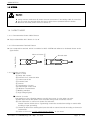
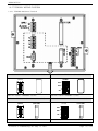
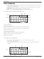
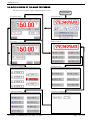
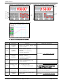
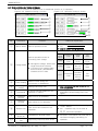
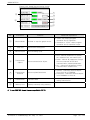
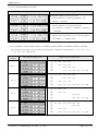
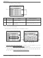
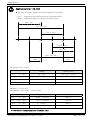
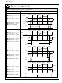
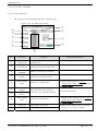
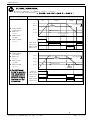
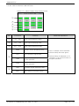
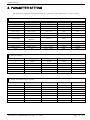
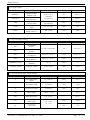
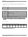
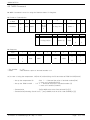
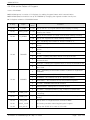
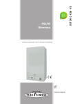
SAMWONTECH 2.12 SYSTEM SETUP ▶ ▶ ▶ ▶ ☞ ☞ Screen for initial setting for operation As it’s possible to approach without a password in case of forwarding from factory, make sure of setting a password at 2.12.3 initialization mark and condition mark lamp Setting when it’s not necessary to block the general user. When it’s changed in a wrong way, the Setting Points within the System Setting Screen can cause a problem in operating an equipment. Figure 2-51. System Setup Screen 1 ○ 5 ○ 2 ○ 6 ○ 3 ○ 7 ○ 4 ○ 8 ○ No. Instruction 1 ○ INPUT SET 2 ○ Contents Additional Explanation Shifts to input and input compensation setting screen. ▶ Refer to 2.12.1 INPUT AND INPUT ▶ COMPENSATION SETTING OUTPUT SET Shifts to control output and transmission setting screen. ▶ Refer to 2.12.2 Control Output AND ▶ TRANSMISSION SETTING 3 ○ INNER SIGNAL Shifts to inner signal setting screen. ▶ Refer to 2.12.3 INNER SIGNAL ▶ SETTING 4 ○ PID GROUP Shifts to PID related setting screen. ▶ Refer to 2.12.4 PID SETTING 5 ○ DO CONFIG Shifts to additional output setting screen. ▶ Refer to 2.12.5 DO CONFIG ▶ SETTING 6 ○ ALARM & DI Shifts to alarm DI setting screen. ▶ Refer to 2.12.6 ALARM AND DI ▶ ERROR NAME SETTING 7 ○ COMM. SET Shifts to communication related setting screen. ▶ Refer to 2.12.7 COMMUNICATION ▶ SETTING 8 ○ INIT DISPLAY Shifts to initial screen related and condition display lamp setting screen. ▶ Refer to 2.12.8 INITIAL DISPLAY AND ▶ CONDITION DISPLAY LAMP SETTING 1st Edition of TEMP880(Eng) IM : May. 12. 2005 Page 55 / 123 SAMWONTECH 2.12.1 INPUT AND INPUT REVISION FOR SECTIONS 2.12.1.1 INPUT SENSOR SETTING Figure 2-52. Input Sensor Setting – DCV Figure 2-53. Input Sensor Setting- DCV 5 ○ 6 ○ 7 ○ 8 ○ 9 ○ 1 ○ 2 ○ 3 ○ 4 ○ 10 ○ No. Instruction Contents 1 ○ SENSOR GROUP 2 ○ SENSOR SET Chooses input sensor. 3 ○ SENSOR UNIT Chooses display unit. ▶ TCC, RTD :℃,℉ ▶ DCV :℃,℉,SPACE,%,Pa,mV,V,%RH,Ω 4 ○ TC SELECT Chooses RJC use when sensor input kind is TC. ▶ You can choose T C, T+R, RJC. 5 ○ RANGE SET Sets sensor usage range. 6 ○ DOT POSITION Chooses below decimal point when sensor kind is “DCV.” ▶ Displays SENSOR GROUP = DCV 7 ○ SCALE SET Sets temperature usage range when sensor kind is “DCV.” ▶ Displays SENSOR GROUP = DCV 8 ○ ALL BIAS Sets the previous range revision value. ▶ Refer to 2.12.1.2 SECTION INPUT ▶ REVISION SETTING 9 ○ FILTER TIME Removes noise when measuring input includes noise of high frequency. 10 ○ HIDDEN BUTTON Chooses input sensor kind. Shifts section input revision setting. Additional Explanation ▶ You can choose T C, RTD, DCV. ▶ ▶ ▶ ▶ Displays 2.13 PASSWORD INPUT screen. Refer to 2.12.1.2 SECTION INPUT REVISION SETTING ☞ cannot change sensor kind during operation. ☞ Displays “S.OPN“ when sensor is disconnected. Displays PRESET OUTPUT for Control Output (MV). 1st Edition of TEMP880(Eng) IM : May. 12. 2005 Page 56 / 123 SAMWONTECH Kinds of Sensor Input No SENSOR SET Temperature Range (℃) Temperature Range (℉) 1 K1 -200.0~1370.0 -300.0~2500.0 TC-K1 2 K2 -200.0~1000.0 0.0~2300.0 TC-K2 3 J -200.0~1200.0 -300.0~2300.0 TC-J 4 E -200.0~1000.0 -300.0~1800.0 TC-E 5 T -200.0~400.0 -300.0~750.0 TC-T 6 R 0.0~1700.0 32~3100 TC-R 7 B 0.0~1800.0 32~3300 8 S 0.0~1700.0 32~3100 TC-S 9 L -200.0~900.0 -300.0~1600.0 TC-L 10 N -200.0~1300.0 -300.0~2400.0 TC-N 11 U -200.0~400.0 -300.0~750.0 TC-U 12 W 0.0~2300.0 32~4200.0 TC-W 13 PlatinelⅡ 0.0~1390.0 -32.0~2500.0 TC-P 14 PTA -200.0~850.0 -300.0~1560.0 PTA 15 PTB -200.0~500.0 -300.0~1000.0 PTB 16 PTC -50.00~150.00 -148.0~300.0 17 JPTA -200.0~500.0 -300.0~1000.0 JPTA 18 JPTB -50.00~150.00 -148.0~300.0 JPTB 19 0.4~2.0V 0.400~2.000V 0.4-2V 20 1~5V 1.000~5.000V 1-5V 21 0~10V 0.00~10.00V 22 -10~20mV -10.00~20.00mV -10-20 23 0~100mV 0.0~100.0mV 0-100 SENSOR GROUP T/C RTD DCV DISP TC-B PTC 0-10V ☞ Display : -5% ~ +105% of the above range 1st Edition of TEMP880(Eng) IM : May. 12. 2005 Page 57 / 123 SAMWONTECH Engineering Units – EU, EUS ▶ EU, EUS are used to explain the interior parameter of controller. ☞ EU( ) : Engineering unit value according to instrument range. ☞ EUS( ) : Engineering range according to instrument span. | RH - RL | EU -100~100% EU 0~100% RL 0 RH EUS 0~100% | RH - RL | EUS -100~100% | RL | | RH | ▶ Range of EU( ), EUS( ) RANGE CENTER POINT EUS -100 ~ 100% RL ~ RH | RH – RL | / 2 + RL EUS -100 ~ 100% - ( | RH – RL | + | RL | ) ~ RH RL EUS -100 ~ 100% 0 ~ | RH – RL | | RH – RL | / 2 EUS -100 ~ 100% - | RH – RL | ~ | RH – RL | 0 ▶ INPUT = T C(TC-K1) ▶ RANGE = -200.0℃(RL) ~ 1370.0℃(RH) RANGE CENTER POINT EUS -100 ~ 100% - 200.0 ~ 1370.0℃ 585.0℃ EUS -100 ~ 100% - 1770.0 ~ 1370.0℃ - 200.0℃ EUS -100 ~ 100% 0 ~ 1570.0℃ 785.0℃ EUS -100 ~ 100% - 1570.0 ~ 1570.0℃ 0.0℃ ☞ ABS doesn’t change along input of absolute value. 1st Edition of TEMP880(Eng) IM : May. 12. 2005 Page 58 / 123 SAMWONTECH 2.12.1.2 SECTION INPUT REVISION SETTING ▶ Section revision is applied as a form of linear equation between each revision points. Figure 2-54. Section Input Revision Setting 1 ○ 2 ○ 3 ○ No. Instruction Contents 1 ○ DRY TEMP DIFFERENCE VALUE Sets revision temperature at each standard temperature. 2 ○ DRY TEMP REFERENCE POINT Sets each standard temperature. 3 ○ BIASED DRY TEMP PV Display temperature input revision is applied. 1st Edition of TEMP880(Eng) IM : May. 12. 2005 Additional Explanation Page 59 / 123 SAMWONTECH Section Input Revision Setting ▶ ▶ ▶ ▶ ▶ Indicates section input revision at the temperature S.PV = Actual SensorTemperature, B.PV = Temperature after the revision, input, RH = Above input Pn(P) = Standard Temperature, Pn(D) = Revision Temperature (POINT n.DPV= P n(P), POINT n.DDV= Pn(D)) (n = 1, 2, 3, 4, 5, 6, 7, 8 ) RL = Below P8(D) P6(D) P7(D) P5(D) P4(D) P3(D) P2(D) P1(D) B.PV S.PV RL P1(P) P2(P) P3(P) P4(P) P5(P) P6(P) P7(P) P8(P) RH ▶ B.PV at RL ~ POINT1 = S.PV + P1(D) ▶ B.PV at POINT1 ~ POINT2 ( P2(D) – P1(D) ) = S.PV + ( S.PV – P1(P) ) X + P1(D) ( P2(P) – P1(P) ) ▪ ▪ ▪ ▪ ▶ B.PV at POINT7 ~ POINT8 = S.PV + ( S.PV – P7(P) ) X ( P8(D) – P7(D) ) ( P8(P) – P7(P) ) + P7(D) ▶ B.PV at POINT8 ~ RH = S.PV + P8(D) 1st Edition of TEMP880(Eng) IM : May. 12. 2005 Page 60 / 123 SAMWONTECH 2.12.2 CONTROL OUTPUT AND TRANSMISSION SETTING SCREEN 2.12.2.1 CONTROL OUTPUT SETTING Figure 2-55. Temperature (heat) Control Output Setting Figure 2-56. Cooling Control Output Setting 1 ○ 2 ○ 3 ○ 4 ○ 5 ○ No. Instruction 1 ○ OUTPUT 2 ○ CYCLE 3 ○ AT GAIN Contents Sets a kind of control output. Sets output cycle when Control Output is “ SSR (Solid State Relay ) ” Adjusts PID manually according to the characteristic of system after auto tuning. Cuts PID output from STOP, S.OPN, ERROR occurring and displays PRESET OUT 4 ○ PRESET OUT 5 ○ DIRECTION Sets right and reverse motion of PID control. 6 ○ ANTI RESET WIND-UP Prevents excessive integral at setting point. 1st Edition of TEMP880(Eng) IM : May. 12. 2005 6 ○ Additional Explanation ▶ COOL OUTPUT : heat/ cool control ▶ NONE: general control, display 0.0% ▶ for cool output ▶ Controls senstively if output cycle is ▶ short. ▶ Control Output = PID X GAIN ▶ General Control: H.PRESET OUT ▶ heat/cool : H.PRESET OUT ▶ heat/cl : C.PRESET OUT Page 61 / 123 SAMWONTECH Right And Reverse Motion Control Output(MV) 100 % Right Reverse Control output increase when PV> SP. Control output increase when PV< SP - + 0% Deviation(PV -SP) CYCLE TIME ▶ Applies only when a kind of control output is “SSR(Solid State Relay)” ▶ Indicates on/off time of one cycle. ▶ where output cycle is 10 sec. Control Output : 30% Control Output : 50% 10sec 10sec Control Output : 70% 10se c ON OFF ON OFF ON OFF 3sec 7sec 5sec 5sec 7sec 3sec 1st Edition of TEMP880(Eng) IM : May. 12. 2005 Page 62 / 123 SAMWONTECH AT GAIN(AUTO TUNING GAIN) ▶ AT GAIN is used to change the control characteristics based on PID value after auto tuning. ☞ Use calculated setting point after auto tuning ▶ You can adjust AT GAIN based on targets and characterists. 1 ○ AT GAIN < 1.0 → Response time is fast, but hunting is severe. 2 ○ AT GAIN > 1.0 → Overshoot is lessened, but response time is slow.. Gain < 1.0 Gain = 1.0 Gain > 1.0 1st Edition of TEMP880(Eng) IM : May. 12. 2005 Page 63 / 123 SAMWONTECH Anti Reset Wind Up when there is a possibility of the prevention of Anti Reset Wind up when there is no possibility of the prevention of Anti Reset Wind up ▶ ▶ ▶ ▶ One of methods to control during disturbance. Doesn’t operate when PID Setting Point is I=0. Control Output(MV) at PID control MV = P(Proportional value) + I(Integral value) + D(Differential value) PV Setting MV Disturbance Occurrence Disturbance Cancellation When disturbance occurs, Control Output(MV) rises to fit with setting point(SP) and pointing value(PV) drops. If such disturbance sustains for a long time, it takes long time for disturbance to be cancelled due to accumulation of intgral value. Overshoot is large as Figure above and it takes time for pointing value (PV) to be stablized. P BAND PV Setting MV Disturbance Occurrence Disturbance Cancellation From the point where pointing value (PV) enters into P BAND, overshoot is small and PV is stablized fast because accumulation of the integral value is solved. ▶ Example of how to set P BAND → Sensor Input:0.0~100.0℃ , Current Operation PID No. : 1 , P of PID1 group:10.0% , ARW : 200% → P BAND = 200% of P → ARW계산 = 20.0%(P*2) → ARW계값 = 20.0℃(total input*0.2) ☞ MV starts changing from|PV-SP|= P BAND point Ex)Setting Point(SP): Control Output(MV) starts changing from PV:50.0℃ if PV is 70.0℃. → Since |PV-SP|= P BAND, |50.0 -70.0|=20.0 1st Edition of TEMP880(Eng) IM : May. 12. 2005 Page 64 / 123 SAMWONTECH 2.12.2.2 TRANSMISSION OUPUT SET Figure 2-57. Transmission Output Setting 1 ○ 2 ○ No. Instruction Contents Additional Explanation 1 ○ RET. SLELCT Chooses transmission kind. 2 ○ RET. RANGE Sets the range of transmission. ▶ If temperature transmission kind is ▶ “MV”, it’s not displayed. ☞ Transmission output is displayed as 4~20mA. If you want to use transmission output as 1~5V, Please ☞ use it after attaching 250Ω RN-TYPE resistance (precision resistance) at the Transmission output ☞ terminal. Output Based On Transmission Output Kind 1 ○ 2 ○ Case where transmission output is “PV” or “SP” 4.0mA 12.0mA RET RANGE LOW (RL + RH) / 2 20.0mA RET RANGE HIGH Case where transmission output is “MV” 4.0mA 0.0% 1st Edition of TEMP880(Eng) IM : May. 12. 2005 12.0mA 20.0mA 50.0% 100.0% Page 65 / 123 SAMWONTECH 2.12.3 INNNER SIGNAL SETTING SCREEN ▶ Can set eight inner signals. Figure 2-58. Inner Signal Setting Screen 2 ○ 3 ○ 1 ○ 6 ○ 4 ○ 5 ○ No. Instruction Contents Additional Explanation 1 ○ RANGE LOW Sets minimum value of Inner Signal. 2 ○ RANGE HIGH Sets maximum value of Inner Signal. 3 ○ DELAY TIME Sets delay time of Inner Signal. 4 ○ TYPE BUTTON Selects Inner Signal kind to use. 5 ○ BAND BUTTON Selects direction of Inner Signal. ▶ ▶ ▶ ▶ ☞ ☞ ☞ ▶ ▶ Related to 1REF, 2REF output time of 2.12.5 DO CONFIG Setting SP : Present Setting Point PV : Present pointing value It has hysteresis of EUS 0.5% (impossible to change) when selected to PV). TSP : Target setting point during program control. Screen Move Sets eight inner signals using UP, ▶ Switches screen to two Inner Signal Button DOWN button. ▶ units. ☞ If slope for fix operation is set, “TSP” operates as “TSP” of program control. But if slope is not set, “TSP” ☞ operates as “SP”. 6 ○ Operating Direction of Inner Signal RL(℃,%) RNG.LOW RNG.HIGH RH((℃,%) IS Operating [ BAND = INB] 1st Edition of TEMP880(Eng) IM : May. 12. 2005 RL(℃,%) RNG.LOW RNG.HIGH IS Operating RH((℃,%) IS Operating [ BAND = OUTB] Page 66 / 123 SAMWONTECH Example of Inner Signal Operation ▶ Inner Signal Operation According To Setting Point Setting Inner Signal Move SEG1 ▶ INPUT = 0.0 ~ 100.0 → EUS 0.5% = 0.5 ▶ OPER. MODE = PROG SEG2 HYS 50.5 SEG3 SEG4 SEG5 PV 50.0 INB ▶ ▶ ▶ ▶ ▶ TYPE = PV RANGE LOW = 30.0℃ RANGE HIGH = 50.0℃ DIRECT = IN BAND DELAY TIME = 00.00 30.0 HYS 29.5 ON IS OFF SEG1 ▶ INPUT = 0.0 ~ 100.0 → EUS 0.5% = 0.5 ▶ OPER. MODE = PROG ▶ ▶ ▶ ▶ ▶ TYPE = PV RANGE LOW = 30.0℃ RANGE HIGH = 50.0℃ DIRECT = OUT BAND DELAY TIME = 00.00 SEG2 HYS 49.5 SEG3 SEG4 SEG5 PV OUTB 50.0 30.0 HYS 30.5 OUTB ON IS OFF SEG1 SEG2 ▶ INPUT = 0.0 ~ 100.0 SEG3 SEG4 SEG5 SP ▶ OPER. MODE = PROG 50.0 ▶ ▶ ▶ ▶ ▶ 30.0 INB TYPE = SP RANGE LOW = 30.0℃ RANGE HIGH = 50.0℃ DIRECT = IN BAND DELAY TIME = 00.10 DELAY TIME ON IS OFF SEG1 ▶ INPUT = 0.0 ~ 100.0 SEG2 SEG3 SEG4 SEG5 SP OUTB ▶ OPER. MODE = PROG 50.0 ▶ ▶ ▶ ▶ ▶ 30.0 TYPE = TSP RANGE LOW = 30.0℃ RANGE HIGH = 50.0℃ DIRECT = OUT BAND DELAY TIME = 00.00 OUTB ON IS OFF 1st Edition of TEMP880(Eng) IM : May. 12. 2005 Page 67 / 123 SAMWONTECH 2.12.4 PID SET SCREEN 2.12.4.1 PID RANGE SET ▶ Consists of 3 Temperature PID and 1 deviation PID. Figure 2-59. PID Range Set Screen 1 ○ 2 ○ 10 ○ 5 ○ 6 ○ 3 ○ 7 ○ 4 ○ 8 ○ 9 ○ No. Instruction Contents 1 ○ REFERENCE DEVIATION Sets deviation for selecting deviation PID. 2 ○ REFERENCE HYSTERESIS Selects hysteresis width when selecting PID group at Zone PID. 3 ○ RUNNING PID NUMBER Displays operating PID number. 4 ○ CONTROL MODE Sets D.DV or D.PV as operation mode when controls PID. ₩ Additional Explanation 5 ○ TEMP RANGE HIGH High limit of temperature. ▶ ▶ ▶ ☞ 6 ○ Sets limit value which selects ZONE PID for temperature SPAN. ▶ RL≤RP1≤RP2≤RH 7 ○ REFERENCE POINT2 REFERENCE POINT1 8 ○ TEMP RANGE LOW. Low limit of temperature. ▶ ▶ ▶ ☞ 9 ○ 10 ○ ZONE PID Temperature PID group. RDV PID Deviation PID 1st Edition of TEMP880(Eng) IM : May. 12. 2005 It changes as TEMP.RH(TEMP RANGE HIGH) setting point of 2.12.1.1 Temperature Input Setting changes. Cannot amend. It changes as TEMP.RL ▶ (TEMP RANGE LOW) setting point of 2.12.1.1 Temperature Input Setting changes. Cannot amend. ▶ Shifts to the setting screen of target ▶ PID group if you press number. Page 68 / 123 SAMWONTECH PID Group And Control Mode ZONE PID(PID1~3) Contents RH PV ▶ PID group is set by pointing value (PV). ▶ Therefore, PID group may change continuously if pointing value shakes near RP1 or RP2. ▶ To prevent the frequent shake or PID group, set hysteresis (RHY). RP2 RHY RP1 RHY RL PID1 PID3 PID2 Deviation PID(PID4) Contents RH PV RDV SP RDV RL PID4 ZONE PID ▶ Deviation PID can be used when setting RDV (deviation setting point). ▶ Controls deviation PID when pointing value minus setting point is bigger deviation setting point (RDV). PID4 D.DV Control Contents ▶ During D.DV control, since changing rate of output (MV) is small, overshoot is little and time to target setting point (TSP) is delayed a little bit. Setting Point (SP) PV ▶ Suitable for a device which responses sensitively upon output (MV) changing rate. D.PV Control Setting Point (SP) Contents ▶ During D.DV control, since changing rate of output (MV) is large, overshoot happens and time to target setting point (TSP) is faster than D.DV control time. PV ▶ Suitable for a device which responses slowly upon output (MV) changing rate.) 1st Edition of TEMP880(Eng) IM : May. 12. 2005 Page 69 / 123 SAMWONTECH Auto Tuning and Tuning Point ▶ ▶ ▶ ▶ ▶ ▶ Auto Tuning is a function which controller automatically measures and calculates its characteristics, and sets an optimal PID number automatically. Auto Tuning makes ON/OFF Control Output for 2.5 cycling time, and calculate P.I.D by the cycle and amplitude by using Limit Cycle method to target subject to control. AutoTuning only operates for fix operation. It automatically sets calculated P,I,D value at PID group where setting point is located. ▶ Auto Tuning Operation According to Setting Point Setting ▶ OPER. MODE = FIX RUN ▶ INPUT = RTD(PTC) ▶ RANGE = -50.00℃ ~ 150.00℃ ▶ AUTO TUING POINT = 0.25%(fixed) → EUS 0.25% = 0.5℃ ▶ SP = 50.0℃ ▶ OL = 0.0% ▶ OH = 100.0% Auto Tuning PID AUTO TUNING POINT PV 50.5℃ SP = 50.0℃ 49.5℃ Auto Tuning Operation OH ON ON ON MV OFF OFF OL ▶ → → → → → → → Caution for AutoTuning Even if setting point is changed during Auto Tuning, Tuning Point does not change. And it starts controlling using new setting point after Auto Tuning Stop as target setting point. Auto Tuning stops if input S.OPN occurs during Auto Tuning. P, I, D maintains the previous setting point. P, I, D setting point may be changed during Auto Tuning, but will be reset to calculated P, I, D at the time of Auto Tuning Stop. If Auto Tuning is forced to stop, P, I, D value maintains setting point before Auto Tuning Stop. 1st Edition of TEMP880(Eng) IM : May. 12. 2005 Page 70 / 123 SAMWONTECH 2.12.4.2 PID GROUP (PID1~PID4) SETTING ▶ Generally, it uses value calculated by Auto Tuning, but users can set manually as well. Figure 2-60. PID Group (general) Figure 2-61. PID Group (heat/cool) 1 ○ 2 ○ 3 ○ 6 ○ 4 ○ 5 ○ No. 7 ○ Instruction Contents Additional Explanation ▶ Lessens the different between setting ▶ point(SP) and the pointing value ▶ (PV). 1 ○ PROPORTIONAL BAND 2 ○ INTEGRAL TIME 3 ○ DERIVATIVE TIME Sets proportional band. Sets integral time. ☞ ☞ ☞ ☞ ☞ ☞ ☞ ▶ ▶ ▶ ▶ ▶ ▶ ▶ ▶ Large proportional band: PV approaches to SP quickly, but vibration of MV will affect adversely upon safety of control. Small proportional band: PV approaches to SP slowly, and remaining deviation may occur. Expanding integral time: Control Output(MV) is lessened. Therefore, approaching time to setting point(SP) is lengthened. Shortening integral time: Control Output(MV) is increased. Therefore, approaching time to setting point is shortened. ☞ ☞ ☞ ☞ ☞ Intergal operation can eliminate remaining derivitation at program operation. If integral time is too short, controlling may become impossible. ▶ It restraints PV-SP changing rate by ▶ caculating MV which rises along PV▶ SP changing rate. Sets derivative time. 1st Edition of TEMP880(Eng) IM : May. 12. 2005 ☞ It restraints a radical change of PV or ☞ disturbance and accerates the ☞ approach to setting point(SP). Page 71 / 123 SAMWONTECH 4 ○ OUTPUT LIMIT HIGH Sets control output operation range limit high. 5 ○ OUTPUT LIMIT LOW 6 ○ DEAD BAND 7 ○ MANUAL RESET Sets control output operation range limit low. Parameter to set Dead Band of heat/cool run. Parameter to apply manually integral time of PID if integral time(I) is ‘0’ at PID control. 1st Edition of TEMP880(Eng) IM : May. 12. 2005 ▶ OH > OL Page 72 / 123 SAMWONTECH 2.12.5 DO CONFIG SETTING SCREEN ▶ Setting relay which displays operation signal through I/O relay board. Figure 2-62. DO CONFIG Setting – 1Screen Figure 2-63. DO CONFIG Setting – 2Screen 3 ○ 2 ○ 1 ○ Figure 2-64. DO CONFIG Setting – 3Screen Figure 2-65. DO CONFIG Setting – 4Screen 4 ○ 8 ○ 5 ○ 9 ○ 7 ○ 10 ○ 6 ○ 11 ○ No. Instruction Contents 1 ○ INNER SIGNAL Sets relay number to display Inner Signal. ▶ Refer to 2.12.3 Inner Signal Setting 2 ○ TIME SIGNAL Sets relay number to display Time Signal. ▶ Refer to 2.10.4 Time Signal Setting 3 ○ ALARM SIGNAL Sets relay number to display Alarm Signal. ▶ Refer to 2.12.6 Alarm and DI ERROR ▶ Name Setting ▶ 4 ○ RUN SIGNAL Sets relay number to display Operation (Run) Signal. ▶ Displays during fix operation (run) or ▶ program operation. ▶ Relay is turned on after time you set. 1st Edition of TEMP880(Eng) IM : May. 12. 2005 Additional Explanation Page 73 / 123 SAMWONTECH 5 ○ 6 ○ UP SIGNAL DOWN SIGNAL Sets relay number to display Up Signal. Sets relay number to display Down Signal. ▶ FIX RUN → It can be established and operated up ▶ to ( – EUS 10% ~ EUS 10% ). ▶ PROG RUN → Relay is turned on for [Target Setting ▶ Point(TSP) – Setting Temperature ] → Although it can be established up to ▶ ( – EUS 10% ~ EUS 10% ), it can be ▶ operated within the sector of ( 0 ~ ▶ EUS 10% ). ☞ Status lamp and relay of Operation ☞ Screen operate together. 7 ○ SOAK SIGNAL Sets relay number to display soak signal. ▶ ▶ ▶ ▶ ▶ During fix operation, status lamp is displayed, but no relay. During Program Operation, status lamp and relay are turned on for [(SOAK TIME) – Setting Time] 8 ○ ERROR SIGNAL Sets relay number to display signal when error occurs. ▶ Relay is turned on for time you set ▶ when error of D12~D18 occurs. 9 ○ PATTERN END SIGNAL Sets relay number to output Program Operation End signal. ▶ Relay is turned on as long as time is ▶ set when program operation ends. 10 ○ 1st REF. SIGNAL Sets relay number to output signal for the 1st cooler operation. ▶ Relay is turned on after seconds that ▶ you set after Inner Signal1(IS1) is ▶ displayed. 11 ○ 2nd REF. SIGNAL Sets relay number to output signal for the 2nd cooler operation. ▶ Relay is turned on after minutes that ▶ you set after Inner Signal1(IS1) is ▶ displayed. ☞ Case where relay numbers are overlapped: If any signal is displayed, relay operates (“OR” condition). 1st Edition of TEMP880(Eng) IM : May. 12. 2005 Page 74 / 123 SAMWONTECH UP, SOAK, DOWN SIGNAL ▶ INPUT = TEMP(PT_1), RANGE = -50.00℃ ~ 150.00℃ ▶ UP, DOWN SIGANL RANGE → [EUS 0% ~ EUS 10% ] = [ 0.00 ℃ ~ 20.00 ℃ ] Setting UP, SOAK, DOWN RELAY MOTION According to Setting Point UP SOAK DOWN 50.0℃ ▶ OPER. MODE → PROG RUN ▶ TEMP UP → 0.2 ℃ ▶ TEMP SOAK → 2 MIN ▶ TEMP DOWN → 0.2 ℃ 30.2℃ DOWN Setting 30.0℃ SOAK Setting시 간2MIN ON TEMP SOAK RELAY OUT TEMP DOWN RELAY OUT ▶ OPER. MODE → FIX RUN ▶ TEMP UP → 0.2 ℃ ▶ TEMP SOAK → 2 MIN ▶ TEMP DOWN → 0.2 ℃ ☞ For SOAK signal, During fix operation, only status lamp for operation screen is turned on during fix operation (no relay is turned on). UP Setting SP 49.8℃ SOAK ON ON ON 50.0℃ UP Setting PV 49.8℃ 30.2℃ DOWN Setting 30.0℃ SP TEMP UP RELAY OUT ON TEMP SOAK LAMP OUT TEMP DOWN RELAY OUT 1st Edition of TEMP880(Eng) IM : May. 12. 2005 ON ON ON Page 75 / 123 SAMWONTECH 2.12.6 ALARM AND DI ERROR NAME SETTING 2.12.6.1 ALARM SETTING Figure 2-66. Alarm Setting Screen 5 ○ 1 ○ 2 ○ No. Instruction 1 ○ DI SELECT 3 ○ 4 ○ Contents Selects a kind for error. Additional Explanation ☞ Refer to PAGE77 Error Operation Display Alarm Types Direction Wait Operatio n AH.F Upper limit of PV Right Nothing AL.F Lower limit of PV Right Nothing DH.F Upper limit of deviation Right Nothing DL.F Lower limit of deviation Right Nothing DH.R Upper limit of deviation Reverse Nothing DL.R Lower limit of deviation Reverse Nothing Reverse Nothing Reverse Nothing DO.F DI.F 2 ○ ALARM TYPE SELECT Selects a kind for alarm. Out of the range of upper and lower limit of deviation Within the range of upper and lower limit deviation AH.R Upper limit of PV Reverse Nothing AL.R Lower limit of PV Reverse Nothing AH.FS Upper limit of PV Right Existent AL.FS Lower limit of PV Right Existent DH.FS Upper limit of deviation Right Existent DL.FS Lower limit of deviation Right Existent DH.FS Upper limit of deviation Reverse Existent DL.RS Lower limit of deviation Reverse Existent Right Existent Right Existent DO.FS DI.FS Out of the range of upper and lower limit of deviation Within the range of upper and lower limit deviation AH.RS High Limit Pointing Value Reverse Existent AL.RS Low Limit Pointing Value Reverse Existent 1st Edition of TEMP880(Eng) IM : May. 12. 2005 Page 76 / 123 SAMWONTECH 3 ○ ALARM POINT Sets alarm value. 4 ○ ALARM HYSTERESIS Sets hysteresis for alarm operation. 5 ○ NEXT BUTTON Shifts to DI Error Name Setting Screen. ▶ Refer to 2.12.5.2 DI Error Name Setting ☞ Alarm Operation also runs during operation stop status. Alarm Operation ON▶ PV Upper limit HYS PV ▲ ALM ◀OFF ON▶ Upper limit of deviation ◀ON PV Lower limit Out of the upper and lower limit of deviation Within the upper and lower limit of deviation HYS PV ▲ ALM ◀ON Lower limit of deviation OFF▶ HYS DEV - ▲ ALM OFF▶ + OFF▶ + HYS DEV - △ SP ◀OFF ▲ ALM ON▶ ▲ ALM + OFF▶ + ◀ON HYS ◀OFF ▲ ALM HYS DEV=0 △ SP ON▶ DEV - HYS DEV - △ ◀OFF SP ◀ON HYS ▲ ALM 1st Edition of TEMP880(Eng) IM : May. 12. 2005 DEV=0 △ SP ▲ ALM Page 77 / 123 SAMWONTECH Error Operation DI SELECT DI1 DI2 DI3 DI4 DI5 DI6 DI7 DI8 Operation ON OFF OFF OFF OFF OFF OFF OFF RUN/STOP OFF ON OFF OFF OFF OFF OFF OFF ERROR 2 OFF OFF ON OFF OFF OFF OFF OFF ERROR 3 OFF OFF OFF ON OFF OFF OFF OFF ERROR 4 OFF OFF OFF OFF ON OFF OFF OFF ERROR 5 OFF OFF OFF OFF OFF ON OFF OFF ERROR 6 OFF OFF OFF OFF OFF OFF ON OFF ERROR 7 OFF OFF OFF OFF OFF OFF OFF ON ERROR 8 ON OFF OFF - - - - - RUN OFF ON OFF - - - - - STOP OFF OFF ON - - - - - HOLD OFF OFF OFF ON - - - - STEP - - - - OFF OFF OFF OFF PATTERN 1 - - - - ON OFF OFF OFF PATTERN 2 - - - - OFF ON OFF OFF PATTERN 3 - - - - ON ON OFF OFF PATTERN 4 - - - - OFF OFF ON OFF PATTERN 5 - - - - ON OFF ON OFF PATTERN 6 - - - - OFF ON ON OFF PATTERN 7 - - - - ON ON ON OFF PATTERN 8 - - - - OFF OFF OFF ON PATTERN 9 - - - - ON OFF OFF ON PATTERN 10 - - - - OFF ON OFF ON PATTERN 11 - - - - ON ON OFF ON PATTERN 12 - - - - OFF OFF ON ON PATTERN 13 - - - - ON OFF ON ON PATTERN 14 - - - - OFF ON ON ON PATTERN 15 - - - - ON ON ON ON PATTERN 16 ERR PTN 1st Edition of TEMP880(Eng) IM : May. 12. 2005 Page 78 / 123 SAMWONTECH 2.12.6.2 DI ERROR NAME SET Figure 2-67. DI Error Name Setting Screen 4 ○ 1 ○ 2 ○ 3 ○ No. Instruction 1 ○ BUZZER TIME 2 ○ Contents Additional Explanation Sets time for DI Error buzzer. ▶ Although it is set to“0”, alarm goes ▶ off for at least one minute. DI1 Using DI1, you can select operation status (RUN / STOP ). ☞ Cannot amend. 3 ○ DI2 ~ DI8 NAME SET You can set DI error name up to nine letters (English or number). ▶ Refer to 2.10.6.1 How To Set Pattern ▶ Name for DI name setting. 4 ○ NEXT BUTTON Moves to Alarm Setting Screen. ▶ Refer to 2.12.6.1 Alarm Setting 2.12.6.3 SCREEN DURING DI ERROR OCCURRENCE Figure 2-68. Screen During DI Error Occurrence 1 ○ 2 ○ 3 ○ No. Instruction Contents 1 ○ EXIT BUTTON Exits error screen. 2 ○ STOP BUTTON Turns off alarm sound. 3 ○ DI ERROR ON Reverses lamp and name of DI which has error. Additional Explanation ▶ Returns to Operation Screen. ☞ Displays error screen again if error is ☞ not resolved.☞ ▶ Displays red. ☞ It becomes green after error is ☞ removed. ☞ Operation stops if DI2~DI8 error occurs 1st Edition of TEMP880(Eng) IM : May. 12. 2005 Page 79 / 123 SAMWONTECH 2.12.7 COMMUNICATION SET ▶ Screen for communication setting. Figure 2-69. Communication Setting Screen 1 ○ 2 ○ 3 ○ 4 ○ 6 ○ 7 ○ 5 ○ No. Instruction 1 ○ PROTOCOL 2 ○ BIT PER SEC 3 ○ STOP BIT 4 ○ PARITY 5 ○ DATA LENGTH 6 ○ ADDRESS 7 ○ RESPONSE TIME Contents Sets communication protocol. Additional Explanation ▶ Operating Program for the company is ▶ PC LINK1(SUM CHECK) Sets communication speed. Sets stop bit. Sets parity. Sets data length. Sets address. ▶ It can be used by connecting and ▶ designating different addresses up to ▶ 99 when communicating via RS485. Sets response time. 1st Edition of TEMP880(Eng) IM : May. 12. 2005 Page 80 / 123 SAMWONTECH 2.12.8 INITIAL DISPLAY and STAUS DISPLAY LAMP SET 2.12.8.1 Initial Display Setting Figure 2-70. Initial Display Setting Screen 7 ○ 8 ○ 1 ○ 2 ○ 3 ○ 4 ○ 5 ○ 6 ○ No. Instruction Contents 1 ○ RUN TIME Records total run (operation) time. Additional Explanation 2 ○ PASSWORD SET Setup password when entering 2.12 System Setting. ▶ ▶ ▶ ▶ ▶ ☞ ▶ The Setting value is “0” when sec is delivered from a factory. Contact where you purchased the product or the company if you forgot password. All data will be initialized to a state of being delivered from a factory. 3 ○ LANGUAGE SET Selects language (English or Chinese) ▶ System inner setting screen displays ▶ English regardless of a kind of ▶ language. 4 ○ INFORMATION1 You can enter company name up to 18 letters of number and English combined. 5 ○ INFORMATION2 You can enter company phone number up to 18 letters of number and English combined. 6 ○ INFORMATION3 You can enter company website address up to 18 letters of number and English combined. 7 ○ NEXT BUTTON Moves to Status Display Lamp Setting Screen. 8 ○ CLEAR BUTTON ▶ Refer to 2.12.8.2 Status Display Lamp ▶ Setting Delete total Operation Time. 1st Edition of TEMP880(Eng) IM : May. 12. 2005 Page 81 / 123 SAMWONTECH 2.12.8.2 STATUS DISPLAY LAMP SETTING Figure 2-71. Status Display Lamp Setting Screen 1 ○ 2 ○ 3 ○ 4 ○ 5 ○ No. Instruction 1 ○ IS1 ~ IS8 Inner signal displaying lamp. 2 ○ TS1 ~ TS4 Time signal displaying lamp. 3 ○ AL1 ~ AL4 Alarm signal displaying lamp. DAMP UDC 4 ○ Contents Auxiliary output displaying lamp. UDC Operation signal lamp. 1.REF Signal displaying lamp for the 1st cooler operation. 2.REF Signal displaying lamp for the 2nd cooler operation. RUN Operation signal displaying lamp. WAIT Wait operation displaying lamp. Additional Explanation ▶ Up to 16 lamps can be selected. ▶ Selected lamp becomes green. ▶ Selected lamp is displayed on fix ▶ operation or the second screen of ▶ program operation. 5 ○ 1st Edition of TEMP880(Eng) IM : May. 12. 2005 Page 82 / 123 SAMWONTECH 2.13 SETUP PASSWORD ▶ Inputs password for entering System Setting Screen or Section Input Revision Screen. Figure 2-72. Setup Password Screen – System Setting Figure 2-73. Password input Screen – Section Input Revision 1 ○ No. Instruction Contents 1 ○ INPUT PASSWORD Inputs password for entering System Setting Screen 2 ○ INPUT PASSWORD Inputs password for entering input revision screen. 1st Edition of TEMP880(Eng) IM : May. 12. 2005 2 ○ Additional Explanation ▶ password for sec is “0” ☞ Switch password at 2.12.8.1 sec ▶ Display Setting. Page 83 / 123 SAMWONTECH ▪ Simple Program EXAMPLE ▶ How to set parameter of TEMP 880 when you wish to occur different kinds of signal and patterns as below. 100.0℃ 90.0℃ 1 Seg 30 min 2vSeg 40 min 3 Seg 30 min 4 Seg 40 min Damp SP 5 Seg 30 min 6 Seg 40 min 100.0% 90.0% 80.0℃ 80.0% 70.0℃ 70.0% 60.0℃ 60.0% 50.0℃ 50.0% 40.0℃ 40.0% 30.0℃ 30.0% 20.0℃ 20.0% 10.0℃ 10.0% 0.0℃ 0.0% Displays when temperature Setting Point(SP) is 40.0~50.0℃ Inner Signal1 (IS1) Inner Signal2 (IS2) Time Signal1 (TS1) Displays when temperature Setting Point(TSP) is not 40.0~50.0℃ Time Signal 1,2 displays as left at each segment.. Time Signal2 (TS2) 1st Edition of TEMP880(Eng) IM : May. 12. 2005 Page 84 / 123 SAMWONTECH 1 Sets pattern. ○ 2 Sets Inner Signal ○ 3 ○ Sets time signal. 1st Edition of TEMP880(Eng) IM : May. 12. 2005 Page 85 / 123 SAMWONTECH 3. PARAMETER SETTING ▶ Table that organizes setting range and sec standard of inner parameters for each screen. 2.7 Operation Setting Symbol Parameter Range Unit Default OPER. MODE OPERATION MODE PROG, FIX ABS PROG POWER MODE POWER MODE STOP, COLD, HOT ABS STOP FUZZY SELECT FUZZY SELECT OFF, ON ABS OFF KEY LOCK KEY LOCK OFF, ON ABS OFF TIME UNIT TIME UNIT HH:MM, MM:SS ABS HH:MM OPER. HOUR OPERATION HOUR 0~9999 ABS 0 OPER. MIN OPERATION MINUTE 0~59 ABS 0 TIME MODE TIME MODE OFF, ON ABS OFF TEMP SLOPE DAMP SLOPE DISP TEMP SLOPE DAMP SLOPE DISP EUS(0~100%)/MIN 0.0 ~ 100.0 DISP , HIDE EUS/MIN ABS ABS EUS(0%)/MIN 0.0/MIN DISP Unit Default 2.8 Reserve Setting Symbol Parameter Range Y YEAR 0~99 ABS 0, 1 M MONTH 1~12 ABS 0, 1 D DAY 1~31 ABS 0, 1 H HOUR 0~23 ABS 0, 1 M MINUTE 0~59 ABS 0, 0 RESERVE MODE RESERVE MODE OFF, ON ABS OFF ange Unit Default 2.9 Graph and Graph Record Setting Symbol Parameter PTNO PATTERN NUMBER 0~120 ABS 0 TEMP SP TEMP SP DISPLAY OFF, ON ABS ON DAMP SP DAMP SP DISPLAY OFF, ON ABS ON OPER. MODE OPERATION MODE STOP, RUN ABS STOP TIME UNIT TIME UNIT SEC, MIN ABS SEC SAMPLING TIME SAMPLING TIME 1~59 ABS 5 BACK UP SELECT BACK UP PTN, PARA, ALL ABS PTN DIRECT SELECT DIRECT DNLOAD, UPLOAD ABS DNLOAD 1st Edition of TEMP880(Eng) IM : May. 12. 2005 Page 86 / 123 SAMWONTECH 2.10.1 Pattern Edit Symbol Parameter Range Unit Default PATTERN NO TEMP STC SSP DAMP PATTERN NUMBER SEGMENT TEMP SP START CODE START SET POINT SEGMENT DAMP SP 1~120 EU(0~100%) SSP, S.PV. T.PV EU(0~100%) 0.0 ~ 100.0 ABS EU ABS EU ABS 1 EU(0%) S.PV EU(0%) 0.0 TIME SEGMENT TIME -0.01(OFF)~99.59 (HOUR.MIN) ABS -0.01(OFF) TS1~TS4 TIME SIGNAL1~4 0~7 ABS 0(OFF) Symbol Parameter Range Unit Default PTN NO PATTERN NUMBER 1~120 ABS 1 PTN RPT PATTERN REPEAT COUNT 0(infinite repeat)~999 ABS 1 LINK PTN LINK PATTERN 0~120 ABS 0 START START SEGMENT 0~99 ABS 0 END END SEGMENT 0~99 ABS 0 COUNT SEGMENT COUNT 0~99 ABS 0 2.10.2 Repeat Setting 2.10.3 File Edit Symbol Parameter Range Unit Default SRC. PTNO SOURCE PATTERN NUMBER 1~120 ABS 0 DES. PTNO DESTINATION PATTERN NUMBER 1~120 ABS 0 DEL. PTNO DELETE PATTERN NUMBER 1~120 ABS 0 2.10.4 Time Signal Setting Symbol Parameter Range Unit Default ON TIME TIME SIGNAL ON TIME 00.00~99.59 (HOUR.MIN) ABS 00.00 OFF TIME TIME SIGNAL OFF TIME 00.00~99.59 (HOUR.MIN) ABS 00.00 2.10.5 Wait Operation Setting Symbol Parameter Range Unit Default WAIT MODE WAIT MODE OFF, ON ABS OFF TEMP ZONE TEMP WAIT ZOME EUS(0~100%) EUS EUS(0%) WAIT TIME WAIT TIME 00.00~99.59 (HOUR.MIN) ABS 00.00 1st Edition of TEMP880(Eng) IM : May. 12. 2005 Page 87 / 123 SAMWONTECH 2.10.6 Pattern Name Setting Screen Symbol Parameter PTNO 1~120 PATTERN NAME 1~120 Range 0~9, A~Z, Special Character (Max.10 Character) Unit ABS Default PROG PT001 ~ PROG PT120 2.11 Screen Choice Symbol Parameter Range Unit Default TUNING KEY TUNING KEY DISPLAY BUTTON HIDE, DISP ABS DISP LIGHT OFF LIGHT OFF 0~99 ABS 10 CONTRAST SET CONTRAST GROUP SET 8 Level ABS 4 Level Range TC , RTD , DCV Refer to Page53 Input Sign ℃,℉ ℃,℉,SPACE,%,Pa, mV,V,%Rh,OHM Unit ABS Default TC ABS T C-K1 ABS ℃(TC,RTD) ABS ℃(DCV) EU(0~100%) TEMP RL < TEMP RH EU EU(100%) EU ABS EUS ABS EU(0%) 1 EUS(0%) 0 ABS 100.0 SCALE LOW -199.9~3000.0 SL < SH ABS 0.0 TC SELECT TC, T+R, RTC ABS T+R Parameter Range Unit Default DIFFERENCE VALUE1~8 EUS(-10~10%) EUS EUS(0%) EU EU(0%) 2.12.1.1 Temperature Input Setting Symbol SENSOR GROUP Parameter SENSOR GROUP SENSOR SET SENSOR SET SENSOR UNIT SENSOR UNIT RANGE SET DOT POSITION ALL BIAS FILTER TIME SCALE SET TC SELECT RANGE HIGH RANGE LOW DOT POSITION ALL BIAS FILTER TIME 0~3 EUS(-105~105%) 0~120 SEC SCALE HIGH 2.12.1.2 Section Input Revision Setting Symbol POINT1.DDV POINT2.DDV POINT3.DDV POINT4.DDV POINT5.DDV POINT6.DDV POINT7.DDV POINT8.DDV POINT1.DPV REFERENCE POINT1 1st Edition of TEMP880(Eng) IM : May. 12. 2005 EU(0~100%) Page 88 / 123 SAMWONTECH POINT2.DPV REFERENCE POINT2 POINT3.DPV REFERENCE POINT3 POINT4.DPV REFERENCE POINT4 POINT5.DPV REFERENCE POINT5 POINT6.DPV REFERENCE POINT6 POINT7.DPV REFERENCE POINT7 POINT8.DPV REFERENCE POINT8 ≤DRY RL ≤ POINT1.DPV ≤ POINT2.DPV ≤ POINT3.DPV ≤ POINT4.DPV ≤ POINT5.DPV ≤ POINT6.DPV ≤ POINT7.DPV ≤ POINT8.DPV ≤ DRY.RH EU EU(100%) EU EU(100%) EU EU(100%) 2.12.2.1 Control Output Setting Symbol Parameter Range Unit Default HEAT OUTPUT HEAT OUTPUT TYPE SSR, SCR ABS SSR HEAT CYCLE HEAT CYCLE TIME 1~300 SEC ABS 1 HEAT AT-GAIN HEAT AUTO TUNING GAIN 0.1~10.0 ABS 1.0 H.PRESET OUT HEAT PRESET OUTPUT -5.0~105.0% % 0.0% DIRECTION OUTPUT DIRECTION REV, FWD ABS REV COOL OUTPUT COOL OUTPUT TYPE SSR, SCR, NONE ABS NONE COOL CYCLE COOL CYCLE TIME 1~300 SEC ABS 1 COOL AT-GAIN COOL AUTO TUNING GAIN 0.1~10.0 ABS 1.0 C.PRESET OUT COOL PRESET OUTPUT -5.0~105.0% % 0.0% ARW SET ANTI RESET WINDUP 0.0(AUTO)~200.0 % 100.0 2.12.2.2 Transmission Output Setting Symbol Parameter Range Unit Default RET. SELECT RETRANSMISSION SELECT PV, SP, MV,HMV,CMV ABS PV EU(0~100%) RET RL < RET RH EU EU(100%) EU EU(0%) RET. RANGE RETRANSMISSION RANGE HIGH RETRANSMISSION RANGE LOW 1st Edition of TEMP880(Eng) IM : May. 12. 2005 Page 89 / 123 SAMWONTECH 2.12.3 Inner Signal Symbol Parameter Range Unit Default RANGE-L INNER SIGNAL RANGE LOW EU(0~100%) RANGE-L ≤ RANGE-H EU EU(0%) RANGE-H INNER SIGNAL RANGE HIGH EU EU(0%) TIME INNER SIGNAL DELAY TIME 00.00~99.59 (HOUR.MIN) ABS 00.00 TYPE INNER SIGNAL TYPE SP, PV, TSP ABS SP BAND INNER SIGNAL BAND DIRECT INB, OUTB ABS INB Range Unit Default RL≤RP1≤RP2≤RH EU EU(100%) 2.12.4.1 PID Range Setting Symbol Parameter RP1 REFERENCE POINT1 RP1 REFERENCE POINT2 RDV REFERENCE DEVIATION EUS(0.0~100.0%) EUS EUS(0.0%) RHY REFERENCE HYSTERESIS EUS(0.0~100.0%) EUS EUS(0.3%) RUNNING PID NO RUNNING PID NUMBER 1,2,3,4 ABS 1 CONTROL MODE CONTROL MODE D.DV, D.PV ABS D.DV 2.12.4.2 PID Group (PID1~PID4) Setting Symbol Parameter Range Unit Default P PROPORTIONAL BAND 0.1~999.9% ABS 5.0% I INTEGRAL TIME 0~6000S ABS 120S D DERIVATIVE TIME 0~6000S ABS 30S DB DEAD BAND -100.0%~15.0 % 3.0% MR MANUAL RESET -5.0~105.0% % 50.0% OH OUTPUT LIMIT HIGH ABS 100.0 OL OUTPUT LIMIT LOW ABS 0.0 1st Edition of TEMP880(Eng) IM : May. 12. 2005 0.0~100.0 OL < OH Page 90 / 123 SAMWONTECH 2.12.5 DO CONFIG Setting Symbol Parameter Range Unit Default IS1~IS8 RELAY INNER SIGNAL1~8 RELAY 0(OFF)~20 ABS 0 TS1~TS4 RELAY TIME SIGNAL1~4 RELAY 0(OFF)~20 ABS 0 AL1~AL4 RELAY ALARM SIGNAL1~4 RELAY 0(OFF)~20 ABS 0 RUN RELAY RUN RELAY 0(OFF)~20 ABS 0 RUN CPARA RUN DELAY TIME 0~999 SEC ABS 0 UP RELAY UP RELAY 0(OFF)~20 ABS 0 UP CPARA UP RANGE EUS(0~10%) EUS EUS(0%) SK RELAY SOAK RELAY 0(OFF)~20 ABS 0 SK CPARA SOAK TIME 0~999 MIN ABS 0 DN RELAY DOWN RELAY 0(OFF)~20 ABS 0 DN CPARA DOWN RANGE EUS(0~10%) EUS EUS(0%) ERROR RELAY ERROR RELAY 0(OFF)~20 ABS 0 ERROR CPARA ERROR TIME 0~999 MIN ABS 0 PTEND RELAY PATTERN END RELAY 0(OFF)~20 ABS 0 PTEND CPARA PATTERN END TIME 0~999 MIN ABS 0 1REF RELAY FIRST REF. RELAY 0(OFF)~20 ABS 0 1REF CPARA FIRST REF. TIME 0~999 SEC ABS 0 2REF RELAY SECOND REF. RELAY 0(OFF)~20 ABS 0 2REF CPARA SECOND REF. TIME 0~999 MIN ABS 0 1st Edition of TEMP880(Eng) IM : May. 12. 2005 Page 91 / 123 SAMWONTECH 2.12.6.1 Alarm Setting Symbol Parameter Range Unit Default DI SELECT DI SELECT ERR, PTN ABS ERR TYPE ALARM TYPE AH.F, AL.F, DH.F DL.F, DH.R, DL.R DO.F, DI.F, AH.R AL.R, AH.FS, AL.FS DH.FS, DL.FS, DH.FS DL.RS, DO.FS, DI.FS AH.RS, AL.RS ABS ALARM1,3 → AH.F ALARM2,4 → AL.F POINT ALARM POINT EU(-105~105%) EU EU(100%) HYS ALARM HYSTERESIS EUS(0~100%) EUS EUS(0.5%) 2.12.6.2 DI Error Name Setting Symbol Parameter Range Unit Default BUZZER TIME BUZZER TIME 0~99 MIN ABS 1 DI2~DI8 NAME DI2~DI8 NAME DI2:ERROR DI3:ERROR DI4:ERROR DI5:ERROR DI6:ERROR DI7:ERROR DI8:ERROR 0~9, A~Z, Special Character (Max of 9 letters) ABS Range Unit Default ABS PCL1 02 03 04 05 06 07 08 2.12.7 Communication Setting Symbol Parameter PCL0 (PC LINK) PCL1(PC LINK with SUM CHECK) MODA(MODBUS ASCII), MODR(MODBUS RTU), SYNM (SYNC MASTER) PROTOCOL PROTOCOL BPS BIT PER SEC 600, 1200, 2400, 4800, 9600 ABS 9600 STOP BIT STOP BIT 1, 2 ABS 1 PARITY PARITY NONE, EVEN, ODD ABS NONE D.LENGTH DATA LENGTH 7, 8 ABS 8 ADDRESS ADDRESS 1 ~99 (Maximum of 99) ABS 1 RESPONSE RESPONSE TIME 0~10 ABS 0 1st Edition of TEMP880(Eng) IM : May. 12. 2005 Page 92 / 123 SAMWONTECH 2.12.8 Initial Display Setting Symbol Parameter Range Unit Default PASSWORD SET PASSWORD SET 0~9999 ABS 0 LANGUAGE SET LANGUAGE SET ENG, CHN ABS ENG INFORMATION1 COMPANY INFORMATION ABS SAMWONTECH CO.,LTD INFORMATION2 TELEPHONE INFORMATION ABS TEL: 82-32326-9120 INFORMATION3 HOMEPAGE INFORMATION ABS WWW.SAMWON TECH.COM 0~9, A~Z, Special Character (Max of 9 letters) 0~9, A~Z, Special Character (Max of 9 letters) 0~9, A~Z, Special Character (Max of 9 letters) 1st Edition of TEMP880(Eng) IM : May. 12. 2005 Page 93 / 123 SAMWONTECH 4. Communication Manual 4.1 Communication Specification ▶ ▶ ▶ ▶ TEMP880 adopts the Half-Duplex type of Communication Interface (RS232C or RS485). In case the Communication Option is RS232C, it is possible to communicate by one to one with a superior rank of communication equipment such as PC. Especially the model of RS485 , it can be used by connecting to a superior rank of communication equipment up to the number of 99. ▶ TEMP880 uses the following parameter during the communication. PARAMETER Setting Value PROTOCOL Communication Speed(BPS) PARITY Contents PCL0 Basic Protocol PCL1 Basic Protocol + Check Sum MODA MODBUS ASCII MODR MODBUS RTU SYNM SYNC MASTER 9600 9600 bps 4800 4800 bps 2400 2400 bps 1200 1200 bps 600 1600 bps NONE None Parity EVEN Even Parity ODD Odd Parity 1 1 bit 2 2 bits 8 8 bits 7 7 bits 1~99 Address STOP BIT DATA LENGTH ADDRESS RESPONDING TIME (=PROCESSING TIME+RESPONSE*10msec) ■ Communication related parameter basic value when forwarding from factory RESPONSE 0~10 • PROTOCOL : PCL1(PC LINK+ Check Sum) • BPS : 9600 bps • PARITY : NONE • STOP BIT : 1 (1 bit) • DATA LENGTH : 8 (8 bits) • ADDRESS :1 • RESPONSE : 0 (dealing time + 10 msec) 1st Edition of TEMP880(Eng) IM : May. 12. 2005 Page 94 / 123 SAMWONTECH 4.2 Communication Wiring ▶ Wiring between the TEMP880 and superior rank of communication equipment is different by the ▶ option(RS232C/RS485) of TEMP880 and the contents are as below. 4.2.1 Connecting the TEMP880 9 Pin connector of RS232C Communication Master Station TEMP880 RD 2 2 RxD TD 3 3 TxD 5 SG RTS 7 CTS 8 SG 5 SHIELD D-Sub 9Pin Female 4.2.2 Connecting the terminal plate of TEMP880 of RS485 Communication Master Station Vertical TEMP880 TEMP880 RTX+ RTX+ RTX+ RTX- RTX- RTX- SG SG SG Vertical SHIELD Terminal Class 3 Ground Terminal Class 3 Ground ☞ MULTIDROP is possible up to the number of 99 in case of SLAVE(TEMP880). ☞ Make sure to connect the vertical section resistance (200Ω 1/4W) in case of the TEMP880 or ▶ MASTER(PC, PLC etc.) 1st Edition of TEMP880(Eng) IM : May. 12. 2005 Page 95 / 123 SAMWONTECH 4.3 Communication Command 4.3.1 Composition of Communication Command ▶ The basic style of Communication Command which transmits a message to TEMP880 from a superior ▶ rank of Communication equipment. 1 ○ 2 ○ 3 ○ 4 ○ 5 ○ , Date followed by the rule of COMMAND 6 ○ S T ADDRESS COMMAND X 1 ○ 7 ○ 8 ○ C L R F SUM Beginning letter of Communication Command Indicate the beginning of Communication Command having a code value (0x02) with a STX (Start of Text), which is a letter of Ascii. 2 ○ ADDRESS Indicate the ADDRESS which is a number of TEMP880 that you intend to communicate with. 3 ○ COMMAND COMMAND for Communication (refer to 4.3.2~4.3.9). 4 ○ Divider Indicate the Divider which separates the Command and Data by comma (','). 5 ○ Data part Indicate the letter line which has a regular form of a letter line followed the Communication Command Rule 6 ○ Check Sum Indicate the inferior rank of 2-byte to D by adding all letters from the letter of after STX to the letter of before SUM using the Ascii code and Use only when the protocol of TEMP880 is “the basic protocol of “PCL!” + Check Sum” 7 , ○ 8 ○ Vertical Section letter Indicate the end of Communication Command as CR(0x0D), LF(0x0A) by using the Ascii code. 1st Edition of TEMP880(Eng) IM : May. 12. 2005 Page 96 / 123 SAMWONTECH 4.3.2 The Kind of Communication Command ▶ The Communication Command of TEMP880 has a Self Information Command which reads the ▶ information of Communication Command and a Read/Write Command which reads all the information of ▶ TEMP880. 1 ○ Self Information Command COMMAND Contents AMI 2 ○ Indicate the model name & version of TEMP880 Read/Write Command COMMAND Contents RSD Series Read of D-Register RRD Random Read of D-Register WSD Series Write of D-Register WRD Random Write of D-Register STD Random Registration of D-Register CLD Call of D-Register which is registered at STD ☞ Each Command can read or write D-Register up to the number of 32. And it should be re-registered ▶ after the power is on in case of STD/CLD when its power source’s off because the registered contents ▶ are initialized. 4.3.3 Error Response ▶ Transmit a message as below in case of Error during a Communication. The number of Byte 1 2 2 2 2 Address NG 숫자2개 SUM S Contents T X 1 1 C L R F ☞ SUM is only used in case the PROTOCOL is “PCL1”. 1st Edition of TEMP880(Eng) IM : May. 12. 2005 Page 97 / 123 SAMWONTECH 4.3.4 RSD Command ▶ RSD Command is used for reading a series of Data on D-Register. ▶ Format of Transmission The number of 1 Byte 2 3 1 2 , The number 1 4 2 S Contents T Addr. RSD , D-Reg. No. 1 1 C L R F SUM X ▶ Response The number of Byte 1 2 3 1 2 1 4 1 4 1 … Addr. RSD , OK , dddd-1 , dddd-2 , … 2 1 1 C L R F S Contents T X 1 , 4 dddd-(n-1) 1 , 4 dddd-(n) SUM - The Number of : 1~32 - dddd F : Data without a point of decimal number (D) ex) In case of reading a D-Register from Temperature PV(D0001) to SP(D0002) - Transmission : [stx]01RSD,02,0001[cr][lf] - Transmission (including Check Sum) : [stx]01RSD,02,0001C5[cr][lf] ([stx] = 0x02, [cr] = 0x0d, [lf] = 0x0a) In case the received value of each PV, SP is 50.0 and 30.0, will be received as below ; - Reception : [stx]01RSD,OK,01F4,012C[cr][lf] - Reception (including Check Sum ) : [stx]01RSD,OK,01F4,012C19[cr][lf] ※ The process of transforming the PV value of received D data to display on screen. 1 ○ 2 ○ Transformation to decimal number : 01F4(16 number-D-) → 500(decimal number) Multiply 0.1 to the transformed value. : 500 * 0.1 → 50.0 1st Edition of TEMP880(Eng) IM : May. 12. 2005 Page 98 / 123 SAMWONTECH 4.3.5 RRD Command ▶ RRD Command is used in case of reading the Random Data on D-Register. ▶Format of Transmission The number of 1 2 Byte 3 1 2 1 4 1 4 1 … RRD , 개수 , D-Reg. No1 , D-Reg. No2 , … S Contents T Addr X 1 4 , ▶ Response The number of Byte 1 1 D-Reg. No(n-1) 4 , 2 D-Reg. No(n) 1 1 C L R F SUM 2 3 1 2 1 4 1 4 1 … Addr RRD , OK , dddd-1 , dddd-2 , … S Contents T X 1 4 1 4 2 , dddd-(n-1) , dddd-n SUM 1 1 C L R F - The number of (~) : 1~32 - dddd F : Data without a point of decimal number (number D) ex) In case of reading the D-Register of PV(D0001), SP(D0002) - Transmission : [stx]01RRD,02,0001,0002[cr][lf] - Transmission (Including Check Sum ) : [stx]01RRD,02,0001,0002B2[cr][lf] In case the value of D0001 is 50.0 and the value of D0002 is 30.0 - Reception : [stx]01RRD,OK,01F4,012C[cr][lf] - Reception (including Check Sum) : [stx]01RRD,OK,01F4,012C18[cr][lf] 1st Edition of TEMP880(Eng) IM : May. 12. 2005 Page 99 / 123 SAMWONTECH 4.3.6 WSD Command ▶ WSD Command is used in case or using the series data of D-Register. ▶ Format of Reception The number 1 of Byte 2 3 1 2 1 4 1 4 1 … Addr WSD , The number , D-Reg. No1 , dddd-1 , … S Contents T X 1 4 , ▶ Response The number of Byte 1 1 dddd-(n-1) 4 , 2 dddd-(n) T 2 3 1 2 2 Addr WSD , OK SUM X 1 C L R F SUM S Contents 1 1 1 C L R F - The number of (~) : 1~32 - dddd F : Data without a point of prime number (number D) ex) In case of using the data for the temperature & supplementation SP(D0103) when driving the FIX - Set up the Temperature SP : 50.0 ℃ → Removal the point of decimal number (500) → move D number (0x01F4) - Set up the Supplementation SP : 80.0 % → Removal the point of decimal number(800) → move to D number(0x0320) - Transmission : [stx]01WSD,02,0102,01F4,0320[cr][lf] - Transmission(including Check Sum ) : [stx]01WSD,02,0102,01F4,0320C4[cr][lf] 1st Edition of TEMP880(Eng) IM : May. 12. 2005 Page 100 / 123 SAMWONTECH 4.3.7 WRD Command ▶ WRD Command is used for using the Random data of D-Register. ▶ Format of Transmission The number 1 2 of Byte 3 1 2 1 4 1 4 1 … , No. of content s , D-Reg. No1 , dddd-1 , … S Contents Addr T WRD X 1 4 , ▶ Response The number of Byte 1 1 D-Reg. No(n) 4 , 2 dddd-(n) 2 3 1 2 2 Addr WRD , OK SUM S Contents T X 1 1 C L R F SUM 1 1 C L R F - The number : 1~32 - dddd F : Data without a point of decimal number of D ex) In case of using the temperature, SP(D0102) while driving the FIX and date at TEMP SLOPE(D0106) - Set up the temperature SP - Set up the TEMP SLOPE : : 50.0 ℃ → Removal the point of decimal number(500) → move to D number(0x01F4) 0.5 ℃ → Removal the point of decimal number (5) → move to D number (0x0005) - Transmission : [stx]01WRD,02,0102,01F4,0106,0005[cr][lf] - Transmission(including Check Sum ) : [stx]01WRD,02,0102,01F4,0106,0005B6[cr][lf] 1st Edition of TEMP880(Eng) IM : May. 12. 2005 Page 101 / 123 SAMWONTECH 4.3.8 STD Command ▶ STD Command is used for registering preferable D-Register to TEMP880 in advance. ▶ Format of Transmission The number 1 2 of Byte 3 1 2 1 4 1 4 1 … , The numb er , D-Reg. No1 , D-Reg. No2 , … 2 1 1 C L R F S Contents Addr T STD X 1 , ▶ Response The number of Byte 1 4 1 D-Reg. No(n-1) 4 , D-Reg. No(n) 2 3 1 2 2 Addr STD , OK SUM S Contents T X SUM 1 1 C L R F - The number of (~) : 1~32 ex) In case of registering the Temperature of PV(D0001), SP(D0002), Supplementation SP(D0003) - Transmission : [stx]01STD,04,0001,0002,0003[cr][lf] - Transmission (including Check Sum ) : [stx]01STD,04,0001,0002,0003A6[cr][lf] 1st Edition of TEMP880(Eng) IM : May. 12. 2005 Page 102 / 123 SAMWONTECH 4.3.9 CLD Command ▶ CLD Command is used for reading & bring the D-Register which is already registered at TEMP880 by ▶ STD Command. ▶ Format of Transmission The number of 1 Byte 2 3 2 Addr CLD SUM S Contents T X ▶ Response The number of Byte 1 1 1 C L R F 2 3 1 2 1 4 1 4 1 … Addr CLD , OK , dddd-1 , dddd-2 , … 2 1 1 C L R F S Contents T X 1 , - 4 dddd-(n-1) 1 , 4 dddd-(n) SUM The number of (~) : 1~32 dddd : Data without a point of decimal number (D) 1st Edition of TEMP880(Eng) IM : May. 12. 2005 Page 103 / 123 SAMWONTECH 4.4 Explanation of D-REGISTER ▶ D-Register is a group of gathering all the data which is provided to check all the condition of TEMP880. ▶ D-Register is grouped by each 100 unit, basically, depending on the contents and the contents are as below. Scope of D-Register Group Contents Read Write D0001~D0099 PROCESS Indication of a basic driving-related information ○ X D0100~D0199 FUNCTION Set up the driving-related Information ○ △ D0200~D0299 RESERVATION Set up the time and reservation functions ○ △ D0300~D0399 IS Set up the inner-signal ○ ○ D0400~D0499 ALARM / TS Set up the Alarming and Time-signal ○ ○ D0500~D0599 HEAT PID Set up the P.I.D at heater ○ ○ D0600~D0699 COOL PID Set up the P.I.D at Freezer ○ ○ D0700~D0799 COMM ○ X D0800~D0899 OUTPUT ○ ○ D0900~D0999 INPUT Set up of input ○ ○ D1000~D1099 PROGRAM Set up the pattern of Program ○ ○ D1100~D1199 RESERVED Preparation X X D1200~D1299 RESERVED Preparation X X D1300~D1399 FILE1 ○ X D1400~D1499 FILE2 ○ X D1500~D1599 FILE3 ○ X D1600~D1699 PROG_INFO ○ ○ D1700~D1799 FILE4 Set up the time-signal1 of segment ○ X D1800~D1899 FILE5 Set up the time-signal2 of segment ○ X D1900~D1999 FILE6 Set up the time-signal3 of segment ○ X D2000~D2099 FILE7 Set up the time-signal4 of segment ○ X D2100~D2399 RESERVED Preparation X X Indication of communication-related information Set up the Control printing & DO printing Indication the temperature TSP of segment Indication of supplement TSP of segment Indication of setting up time of segment Set up the repeating of Pattern& Segment ☞ Each of D-Register is composed of 4 places of D number (2-Byte). 1st Edition of TEMP880(Eng) IM : May. 12. 2005 Page 104 / 123 SAMWONTECH 4.4.1 PROCESS ▶ PROCESS group has basic data from the operation of TEMP880. Among this, there’s Bit Map Information which indicates all the conditions by the unit of Bit and the contents are as below. bit NOWSTS OTHERSTS ISSTS TSSTS ALSTS (D0010) (D0011) (D0012) (D0013) (D0014) 0 RESET IS1 TS1 AL1 1 FIX IS2 TS2 AL2 2 PROG IS3 TS3 AL3 3 HOLD IS4 TS4 AL4 4 WAIT 5 AT 6 7 RUN IS5 IS6 WAIT IS7 ERROR IS8 8 9 1.REF 10 2.REF 11 12 13 14 15 SYSERR DOSTSL DOSTSH DIDATA ERROR (D0015) (D0016) (D0017) (D0018) (D0019) 0 RELAY 1 RELAY 17 DI1 TEMP +OVER 1 RELAY 2 RELAY 18 DI2 TEMP -OVER RELAY 3 RELAY 19 DI3 3 RELAY 4 RELAY 20 DI4 4 RELAY 5 DI5 5 RELAY 6 DI6 6 RELAY 7 DI7 7 RELAY 8 DI8 8 RELAY 9 9 RELAY 10 10 RELAY 11 11 RELAY 12 12 RELAY 13 13 RELAY 14 14 RELAY 15 15 RELAY 16 bit 2 SYS ERR ☞ It’s composed of D-Register which has a real data value except the Bit Map information. 1st Edition of TEMP880(Eng) IM : May. 12. 2005 Page 105 / 123 SAMWONTECH ▶ Common Driving-related D-Register D-Reg. Signs Contents D0001 TEMP_NPV Present Temperature PV D0002 TEMP_NSP Present Temperature SP D0003 DAMP_NSP Present DAMP SP D0006 MVOUT D0007 HOUT Heater Control Printing Value D0008 COUT Freezer Control Printing Value D0009 PIDNO Currently Applied PID No. Temperature Control Printing Value ▶ FIX Driving-related D-Register D-Reg. Signs Contents D0020 PROC_TIME_H PROCESS TIME (hour) when driving FIX D0021 PROC_TIME_L PROCESS TIME (min) when driving FIX ▶ PROGRAM Driving-related D-Register D-Reg. Signs Contents D0025 PTNO D0026 SEGNO D0027 R_TIME_H Remained time(hour) of Segment which is driving now D0028 R_TIME_M Remained time(min) of Segment which is driving now D0029 WAITTIME_H WAIT TIME(hour) when the WAIT motion D0030 WAITTIME_M WAIT TIME(min) when the WAIT motion D0031 N_PT_RPT D0032 PT_RPT D0033 N_SEG_RPT D0034 SEG_RPT D0035 P_TEMP_TSP Temperature TSP(Target Set Point) of previous Segment D0036 N_TEMP_TSP Temperature TSP(Target Set Point) of present Segment D0037 P_DAMP_TSP DAMP TSP(Target Set Point) of previous Segment D0038 N_ DAMP _TSP DAMP TSP(Target Set Point) of present Segment D0039 N_SEG_TIME Program Pattern No. which is driving now Segment No. which is driving now. Repeating frequency of a Pattern which is on the process Repeating frequency of a Pattern which is set up Repeating frequency of a Segment which is on the process Repeating frequency of a Segment which is set up Set up time of Present Segment 1st Edition of TEMP880(Eng) IM : May. 12. 2005 Page 106 / 123 SAMWONTECH 4.4.2 FUNCTION ▶ FUNCTION Group is consist with a D-Register which is related to the motions of TEMP880. ▶ D-Register related to PROGRAM Driving D-Reg. Signs Contents D0100 SET_PTNO D0120 WAITMD D0121 TEMP_WZ Set up the WAIT field of Temperature D0122 WAIT_TM Set up the time of WAIT motion Set up the No. of a pattern which is for driving a Program Set up the condition whether or not to use the WAIT motion ( 0 : OFF 1 : ON ) ▶ D-Register related to FIX Driving D-Reg. Signs Contents D0102 FIX_T_SP Set up the Temperature SP when driving FIX D0103 FIX_D_SP Set up the DAMP SP when driving FIX D0110 OTMSL Set up the condition whether or not to use FIX OP TIME ( 0 : OFF 1 : ON ) D0111 OTM_H Set up the time(hour) of FIX OP TIME D0112 OTM_M Set up the time(min) of FIX OP TIME ▶ D-Register related to Motions D-Reg. D0101 D0104 D0105 Signs MODE Driving Contents Setting Value Contents RUN 1 PROG/FIX RUN HOLD 2 HOLD ON/OFF STEP 3 Segment STEP STOP 4 PROG/FIX STOP PROG 0 Set up the PROG MODE FIX 1 Set up the FIX MODE COLD 0 Set up the COLD MODE HOT 1 Set up the HOT MODE OPMODE PWRMODE ☞ TEMP880 should be at the condition of STOP(PROG STOP/FIX STOP) to execute the PROG RUN or FIX ▶ RUN as a Communication. For example, to change the FIX RUN (present) to PROG RUN, it should be ▶ firstly done the change to PROG STOP(D0104=0001, D0101=0004) and then to PROG RUN. 1st Edition of TEMP880(Eng) IM : May. 12. 2005 Page 107 / 123 SAMWONTECH 4.4.3 RESERVATION ▶ RESERVATION group is consist of Time checking, Setting and Reservation-related D-Register of ▶ TEMP880. ▶ D-Register related to Time D-Reg. Signs D0201 N_YEAR D0202 N_MONTH D0203 Contents Read Write Present time of TEMP880 (year) ○ × Present time of TEMP880 (month) ○ × N_DAY Present time of TEMP880 (day) ○ × D0204 N_HOUR Present time of TEMP880 (hour) ○ × D0205 N_MIN Present time of TEMP880 (min) ○ × D0206 RUN_YEAR Reservation time of TEMP880 (year) ○ ○ D0207 RUN_MONTH Reservation time of TEMP880 (month) ○ ○ D0208 RUN_DAY Reservation time of TEMP880 (day) ○ ○ D0209 RUN_HOUR Reservation time of TEMP880 (hour) ○ ○ D0210 RUN_MIN Reservation time of TEMP880 (min) ○ ○ D0211 SET_YEAR Set up the time (year) × ○ D0212 SET_MONTH Set up the time (month) × ○ D0213 SET_DAY Set up the time (day) × ○ D0214 SET_HOUR Set up the time (hour) × ○ D0215 SET_MIN Set up the time (min) × ○ ▶ Reservation work : ON/OFF D-Reg. Signs D200 RESERVE Driving contents Setting Value Contents OFF 0 Cancellation of reservation ON 1 Setting of reservation 1st Edition of TEMP880(Eng) IM : May. 12. 2005 Page 108 / 123 SAMWONTECH 4.4.4 Set up the Pattern of Program 4.4.4.1 PROGRAM ▶PROGRAM group is consist of D-Register for making Program Pattern with Communication. ▶PROGRAM pattern should be set up at TEMP880 by changing the segment number one by one. ▶ D-Register related to PROGRAM Pattern D-Reg. Signs Setting Value D1000 P_PTNO 1~120 Set up the No. of Program Pattern when reading or writing D1001 DEST_PTNO 1~120 Set up the No. of Program Pattern which will be copied when copying the Pattern D1002 P_SEGNO 0 1~99 D1003 D1004 Set up at the position of D1603~D1618 when reading or writing Set up the Segment No. when reading or Writing 1 INIT : Initializing the contents of D1000~D1004 to '0' 2 READ : Reading with the contents which is set up at D1000 & D1002 3 WRITE : Writing with the contents which is set up at D1000 & D1002 4 PT COPY : Copying the pattern set up at D1000 to the pattern of D1001 5 PT DEL : Deleting the pattern which is set up at D1000 6 SEG INSERT : Inserting to the segment which is set up at D1000& D1002 7 SEG DEL : Deleting the segment which is set up at D1000& D1002 8 ALL PT : Indicating the contents which is set up at D1000 to under the D1300 0 FULL : Exceeding of the limited number of pattern or segment at TEMP880 1 DONE : Order of D1003(TRIGGER) is managed normally 2 PT EMPTY : No contents set up at a pertinent pattern 3 SEG EMPTY : Not contents set up at a pertinent segment 4 PT RUN : TEMP880 PROG RUN condition 5 PARA ERROR : Setting Error of D1000~D1003 6 PT USED : a pertinent pattern is the condition of PROG RUN TRIGGER ANSWER Contents D1010 TEMP_TSP - Setting Value of Temperature TSP (Time Set Point) when reading or writing D1011 DAMP_TSP - Setting Value of DAMP TSP(Time Set Point) when reading or writing D1012 SEG_TIME - Set up time of a segment which to Read or Write D1021 START_CODE - SP starting condition when beginning the Program D1022 SSP_VALUE - Set up the START SP in case of STC=SSP 1st Edition of TEMP880(Eng) IM : May. 12. 2005 Page 109 / 123 SAMWONTECH 4.4.4.2 Reading a Program Pattern ▶ The following order should be performed to read the program pattern which is set up at TEMP880. 1 ○ 2 ○ 3 ○ 4 ○ Set up the Pattern No. of Program at D1000 Set up the No. of Segment at D1002 Set up the READ TRIGGER (‘2’) at D1003 Wait until it’s DONE (‘1’) after reading the data of D1004 5 ○ Read the Temperature, DAMP, TSP and segment time recorded at D1010~D1012. ☞ The above Work from ○ 1 ~ ○ 5 is reading a segment among those which are set up at Program Pattern. ▶ Repeat the work from○ 1 ~ ○ 5 by changing the No. of segment to read and bring several segment. ▶ If the D1002(○ 2 ) is set up at ‘0’, then the contents of D1603~D1618 are brought up. 4.4.4.3 Writing the Program Pattern ▶ The following order should be done to write program pattern at TEMP880. 1 ○ 2 ○ 3 ○ 4 ○ 5 ○ Set up the program pattern at D1000 Set up the segment number at D1002 Set up the temperature, DAMP, TSP and segment time recorded at D1010~D1012. Set up the WRITE TRIGGER ('3') at D1003 Wait until it’s DONE (‘1) after reading the data of D1004 ☞ The above work from ○ 1 ~ ○ 5 is to use one segment at program pattern. To use several segments at ▶ TEMP880, then change then No. of segment and repeat the work of 1 ○ ~ ○ 5 . ▶ The following order should be performed to set up the contents of D1603~D1618 at program writing. 1 ○ 2 ○ 3 ○ 4 ○ 5 ○ 6 ○ 7 ○ 8 ○ Set up the pattern No. of program at D1000 Set up the No. of segment at D1002 Set up the READ TRIGGER ('2') at D1003 Set up the No. of pattern at D1000 Set up the No. of segment to ‘0’ at D1002 Set up the pertinent data at D1603~D1618 Set up the WRITE TRIGGER ('3') at D1003 Wait until it’s DONE (‘1’) after reading the data of D1004 1st Edition of TEMP880(Eng) IM : May. 12. 2005 Page 110 / 123 SAMWONTECH 4.4.4.4 Copy/Delete of Pattern & Insert/Delete of Segment ▶ Copy of Program Pattern 1 ○ 2 ○ 3 ○ 4 ○ Set up the original pattern No. to copy at D1000 Set up the No. of pattern at D1001 to copy the original pattern Set up D1003 PT COPY TRIGGER('4') at D1003 Wait until it’s DONE (‘1) after reading the data of D1004 ▶ Delete of Program Pattern 1 ○ 2 ○ 3 ○ Set up the No. of pattern, which will be deleted, atD1000 Set up PT DEL TRIGGER('5') at D1003 Wait until it’s DONE (‘1) after reading the data of D1004 ▶ Insert of Segment 1 ○ 2 ○ 3 ○ 4 ○ 5 ○ Set up the No. of program pattern at D1000 Set up the No. of segment , which will be inserted, at D1002 Set up the temperature, DAMP, TSP and segment time recorded at D1010~D1012 Set up the SEG INSERT TRIGGER('6') at D1003 Wait until it’s DONE (‘1) after reading the data of D1004 ▶ Delete of Segment 1 ○ 2 ○ 3 ○ 4 ○ Set up the No. of program pattern at D1000 Set up the No. of segment , which will be deleted, at D1002 Set up the SEG DEL TRIGGER('7') at D1003 Wait until it’s DONE (‘1) after reading the data of D1004 1st Edition of TEMP880(Eng) IM : May. 12. 2005 Page 111 / 123 SAMWONTECH D-Register 0000~0599 PROCESS FUNCTION RESERVATION IS ALARM / TS HEAT_PID 0 100 200 300 400 500 SET_PTNO RESERVE HEAT_PB1 HEAT_TI1 NO 0 1 TEMP_NPV STATUS_MODE NOW_YEAR 2 TEMP_NSP FIX_TEMP_SP NOW_MONTH IS1_TYPE HEAT _TD1 3 DAMP_NSP FIX_DAMP_SP NOW_DAY IS1_HIGH HEAT _OH1 4 OP_MODE NOW_HOUR IS1_LOW HEAT _OL1 5 PWR_MODE NOW_MIN IS1_DELAY_TM AL1_MODE HEAT _DB1 IS1_BAND AL2_MODE HEAT _MR1 AL3_MODE HEAT_PB2 AL4_MODE HEAT_TI2 6 MVOUT TEMP_SLOPE RUN_YEAR 7 HOUT DAMP_SLOPE RUN_MONTH 8 COUT FUZZY RUN_DAY IS2_TYPE 9 C_PIDNO TIME UNIT RUN_HOUR IS2_HIGH 10 NOW_STS FIX_OPTM_SELL RUN_MIN IS2_LOW A1_POINT HEAT _OH2 11 OTHER_STS FIX_OPTM_H SET_YEAR IS2_DELAY_TM A2_POINT HEAT _OL2 12 IS_STS FIX_OPTM_M SET_MONTH IS2_BAND A3_POINT HEAT _DB2 13 TS_STS SET_DAY A4_POINT HEAT _MR2 14 AL_STS SET_HOUR IS3_TYPE 15 SYS_ERR_STS SET_MIN IS3_HIGH A1_HYS HEAT_TI3 16 UO_STSSL TEMP_RP1 IS3_LOW A2_ HYS HEAT _TD3 17 UO_STSSH TEMP_RP2 IS3_DELAY_TM A3_ HYS HEAT _OH3 18 DI_DATA RDV IS3_BAND A4_ HYS HEAT _OL3 19 ADERR_STS RHY 20 PROC_TIME_H WAITMD IS4_TYPE TS02_ONTM HEAT _MR3 21 PROC_TIME_M TEMP_WAIT_ZONE IS4_HIGH TS02_OFFTM HEAT_PB4 WAIT_TIME IS4_LOW TS03_ONTM HEAT_TI4 23 IS4_DELAY_TM TS03_OFFTM HEAT _TD4 24 IS4_BAND TS04_ONTM HEAT _OH4 TS04_OFFTM HEAT _OL4 IS5_TYPE TS05_ONTM HEAT _DB4 IS5_HIGH TS05_OFFTM HEAT _MR4 IS5_LOW TS06_ONTM 22 HEAT _TD2 HEAT_PB3 HEAT _DB3 25 RUN_PTNO BLGT_TM 26 RUN_SEGNO BUZZER_TM 27 REMAIN_TIME_H 28 REMAIN_TIME_M 29 WAIT_TIME_H IS5_DELAY_TM TS06_OFFTM 30 WAIT_TIME_M IS5_BAND TS07_ONTM 31 NOW_PT_RPT 32 TOTAL_PT_RPT IS6_TYPE 33 NOW_SEG_RPT IS6_HIGH 34 TOTAL_SEG_RPT IS6_LOW 35 PREV_TEMP_TSP IS6_DELAY_TM DAMP_HIDDEN 1st Edition of TEMP880(Eng) IM : May. 12. 2005 CONTROL_MODE TS07_OFFTM DI_SELECT Page 112 / 123 SAMWONTECH D-Register 0000~0599 PROCESS FUNCTION RESERVATION IS ALARM / TS HEAT _PID 0 100 200 300 400 500 NO 36 NOW_TEMP_TSP IS6_BAND 37 PREV_DAMP_TSP 38 NOW_DAMP_TSP IS7_TYPE 39 NOW_SEG_TIME IS7_HIGH 40 IS7_LOW 41 IS7_DELAY_TM 42 IS7_BAND 43 44 IS8_TYPE 45 IS8_HIGH 46 IS8_LOW 47 IS8_DELAY_TM 48 IS8_BAND 49 50 51 52 53 54 55 56 57 58 59 60 61 62 63 64 65 66 67 68 69 70 71 1st Edition of TEMP880(Eng) IM : May. 12. 2005 Page 113 / 123 SAMWONTECH D-Register 0000~0599 PROCESS FUNCTION RESERVATION IS ALARM / TS HEAT _PID 0 100 200 300 400 500 NO 72 73 74 75 76 77 78 79 80 81 82 83 84 85 86 87 88 89 90 91 92 93 94 95 96 97 98 99 1st Edition of TEMP880(Eng) IM : May. 12. 2005 Page 114 / 123 SAMWONTECH D-Register 0600~1199 COOL_PID COMM OUTPUT INPUT PROGRAM RESERVED 600 700 800 900 1000 1100 0 COOL_PB1 PROTOCOL HEAT_OT IN_GROUP P_PTNO 1 COOL_TI1 BAUD_RATE HEAT_CT SENSOR_TYPE DEST_PTNO 2 COOL _TD1 PARITY HEAT_ATGAIN SENSOR_UNIT P_SEGNO 3 COOL _OH1 STOP_BIT HEAT_PO TEMP_RH TRIGGER 4 COOL _OL1 DATA_LENGTH TEMP_RL ANSWER NO 5 ADDRESS COOL_OT DOT_POS PTN_NAME1 6 RESPONSE COOL_CT ALL_BIAS PTN_NAME2 7 COOL_PB2 COOL_ATGAIN FILTER PTN_NAME3 8 COOL_TI2 COOL_PO TEMP_SH PTN_NAME4 9 COOL _TD2 10 COOL _OH2 DIRECTION 11 COOL _OL2 ARW TEMP_SL TEMP_TSP TC_SELECT DAMP_TSP 12 SEG_TIME 13 TS1 14 COOL_PB3 TS2 15 COOL_TI3 RET_SELECT TS3 16 COOL _TD3 RET_SH TS4 17 COOL _OH3 RET_SL 18 COOL _OL3 19 20 21 COOL_PB4 START_CODE 22 COOL_TI4 SSP_VALUE 23 COOL _TD4 24 COOL _OH4 25 COOL _OL4 26 27 28 29 30 31 32 33 34 35 1st Edition of TEMP880(Eng) IM : May. 12. 2005 Page 115 / 123 SAMWONTECH D-Register 0000~0599 COOL _PID COMM OUTPUT INPUT PROGRAM RESERVED 600 700 800 900 1000 1100 NO 36 37 38 39 40 DO_IS1 41 DO_IS2 42 DO_IS3 43 DO_IS4 44 DO_IS5 45 DO_IS6 46 DO_IS7 47 DO_IS8 48 49 50 DO_TS1 51 DO_TS2 52 DO_TS3 53 DO_TS4 54 55 DO_AL1 56 DO_AL2 57 DO_AL3 58 DO_AL4 59 60 61 62 63 64 65 66 67 68 69 70 DO_RUN 71 DO_RUNPARA 1st Edition of TEMP880(Eng) IM : May. 12. 2005 Page 116 / 123 SAMWONTECH D-Register 0000~0599 COOL _PID COMM OUTPUT INPUT PROGRAM RESERVED 600 700 800 900 1000 1100 NO 72 DO_UP 73 DO_UPPARA 74 DO_SK 75 DO_SKPARA 76 DO_DN 77 DO_DNPARA 78 DO_ERROR 79 DO_ERRORPARA 80 DO_PTEND 81 DO_PTENDPARA 82 DO_1REF 83 DO_1REFPARA 84 DO_2REF 85 DO_REFPARA 86 87 88 89 90 91 92 93 94 95 96 97 98 99 1st Edition of TEMP880(Eng) IM : May. 12. 2005 Page 117 / 123 SAMWONTECH D-Register 1200~1799 RESERVED FILE1 FILE2 FILE3 PROG_INFO FILE4 1200 1300 1400 1500 1600 1700 1 C_TSP1 C_DSP1 C_TM1 C_TS11 2 C_TSP2 C_DSP2 C_TM2 C_TS12 3 C_TSP3 C_DSP3 C_TM3 PT_REPEAT C_TS13 4 C_TSP4 C_DSP4 C_TM4 RPT_SEG_S1 C_TS14 5 C_TSP5 C_DSP5 C_TM5 RPT_SEG_E1 C_TS15 6 C_TSP6 C_DSP6 C_TM6 RPT_SEG_C1 C_TS16 7 C_TSP7 C_DSP7 C_TM7 RPT_SEG_S2 C_TS17 8 C_TSP8 C_DSP8 C_TM8 RPT_SEG_E2 C_TS18 9 C_TSP9 C_DSP9 C_TM9 RPT_SEG_C2 C_TS19 10 C_TSP10 C_DSP10 C_TM10 RPT_SEG_S3 C_TS110 11 C_TSP11 C_DSP11 C_TM11 RPT_SEG_E3 C_TS111 12 C_TSP12 C_DSP12 C_TM12 RPT_SEG_C3 C_TS112 13 C_TSP13 C_DSP13 C_TM13 RPT_SEG_S4 C_TS113 14 C_TSP14 C_DSP14 C_TM14 RPT_SEG_E4 C_TS114 15 C_TSP15 C_DSP15 C_TM15 RPT_SEG_C4 C_TS115 16 C_TSP16 C_DSP16 C_TM16 C_TS116 17 C_TSP17 C_DSP17 C_TM17 C_TS117 18 C_TSP18 C_DSP18 C_TM18 LINK_PT C_TS118 19 C_TSP19 C_DSP19 C_TM19 PT E.MODE C_TS119 20 C_TSP20 C_DSP20 C_TM20 C_TS120 21 C_TSP21 C_DSP21 C_TM21 C_TS121 22 C_TSP22 C_DSP22 C_TM22 C_TS122 23 C_TSP23 C_DSP23 C_TM23 C_TS123 24 C_TSP24 C_DSP24 C_TM24 C_TS124 25 C_TSP25 C_DSP25 C_TM25 C_TS125 26 C_TSP26 C_DSP26 C_TM26 C_TS126 27 C_TSP27 C_DSP27 C_TM27 C_TS127 28 C_TSP28 C_DSP28 C_TM28 C_TS128 29 C_TSP29 C_DSP29 C_TM29 C_TS129 30 C_TSP30 C_DSP30 C_TM30 C_TS130 31 C_TSP31 C_DSP31 C_TM31 C_TS131 32 C_TSP32 C_DSP32 C_TM32 C_TS132 33 C_TSP33 C_DSP33 C_TM33 C_TS133 34 C_TSP34 C_DSP34 C_TM34 C_TS134 35 C_TSP35 C_DSP35 C_TM35 C_TS135 NO 0 1st Edition of TEMP880(Eng) IM : May. 12. 2005 Page 118 / 123 SAMWONTECH D-Register 0000~0599 RESERVED FILE1 FILE2 FILE3 PROG_INFO FILE4 1200 1300 1400 1500 1600 1700 36 C_TSP36 C_DSP36 C_TM36 C_TS136 37 C_TSP37 C_DSP37 C_TM37 C_TS137 38 C_TSP38 C_DSP38 C_TM38 C_TS138 39 C_TSP339 C_DSP39 C_TM39 C_TS139 40 C_TSP40 C_DSP40 C_TM40 C_TS140 41 C_TSP41 C_DSP41 C_TM41 C_TS141 42 C_TSP42 C_DSP42 C_TM42 C_TS142 43 C_TSP43 C_DSP43 C_TM43 C_TS143 44 C_TSP44 C_DSP44 C_TM44 C_TS144 45 C_TSP45 C_DSP45 C_TM45 C_TS145 46 C_TSP46 C_DSP46 C_TM46 C_TS146 47 C_TSP47 C_DSP47 C_TM47 C_TS147 48 C_TSP48 C_DSP48 C_TM48 C_TS148 49 C_TSP49 C_DSP49 C_TM49 C_TS149 50 C_TSP50 C_DSP50 C_TM50 C_TS150 51 C_TSP51 C_DSP51 C_TM51 C_TS151 52 C_TSP52 C_DSP52 C_TM52 C_TS152 53 C_TSP53 C_DSP53 C_TM53 C_TS153 54 C_TSP54 C_DSP54 C_TM54 C_TS154 55 C_TSP55 C_DSP55 C_TM55 C_TS155 56 C_TSP56 C_DSP56 C_TM56 C_TS156 57 C_TSP57 C_DSP57 C_TM57 C_TS157 58 C_TSP58 C_DSP58 C_TM58 C_TS158 59 C_TSP59 C_DSP59 C_TM59 C_TS159 60 C_TSP60 C_DSP60 C_TM60 C_TS160 61 C_TSP61 C_DSP61 C_TM61 C_TS161 62 C_TSP62 C_DSP62 C_TM62 C_TS162 63 C_TSP63 C_DSP63 C_TM63 C_TS163 64 C_TSP64 C_DSP64 C_TM64 C_TS164 65 C_TSP65 C_DSP65 C_TM65 C_TS165 66 C_TSP66 C_DSP66 C_TM66 C_TS166 67 C_TSP67 C_DSP67 C_TM67 C_TS167 68 C_TSP68 C_DSP68 C_TM68 C_TS168 69 C_TSP69 C_DSP69 C_TM69 C_TS169 70 C_TSP70 C_DSP70 C_TM70 C_TS170 71 C_TSP71 C_DSP71 C_TM71 C_TS171 NO 1st Edition of TEMP880(Eng) IM : May. 12. 2005 Page 119 / 123 SAMWONTECH D-Register 0000~0599 RESERVED FILE1 FILE2 FILE3 PROG_INFO FILE4 1200 1300 1400 1500 1600 1700 72 C_TSP72 C_DSP72 C_TM72 C_TS172 73 C_TSP73 C_DSP73 C_TM73 C_TS173 74 C_TSP74 C_DSP74 C_TM74 C_TS174 75 C_TSP75 C_DSP75 C_TM75 C_TS175 76 C_TSP76 C_DSP76 C_TM76 C_TS176 77 C_TSP77 C_DSP77 C_TM77 C_TS177 78 C_TSP78 C_DSP78 C_TM78 C_TS178 79 C_TSP79 C_DSP79 C_TM79 C_TS179 80 C_TSP80 C_DSP80 C_TM80 C_TS180 81 C_TSP81 C_DSP81 C_TM81 C_TS181 82 C_TSP82 C_DSP82 C_TM82 C_TS182 83 C_TSP83 C_DSP83 C_TM83 C_TS183 84 C_TSP84 C_DSP84 C_TM84 C_TS184 85 C_TSP85 C_DSP85 C_TM85 C_TS185 86 C_TSP86 C_DSP86 C_TM86 C_TS186 87 C_TSP87 C_DSP87 C_TM87 C_TS187 88 C_TSP88 C_DSP88 C_TM88 C_TS188 89 C_TSP89 C_DSP89 C_TM89 C_TS189 90 C_TSP90 C_DSP90 C_TM90 C_TS190 91 C_TSP91 C_DSP91 C_TM91 C_TS191 92 C_TSP92 C_DSP92 C_TM92 C_TS192 93 C_TSP93 C_DSP93 C_TM93 C_TS193 94 C_TSP94 C_DSP94 C_TM94 C_TS194 95 C_TSP95 C_DSP95 C_TM95 C_TS195 96 C_TSP96 C_DSP96 C_TM96 C_TS196 97 C_TSP97 C_DSP97 C_TM97 C_TS197 98 C_TSP98 C_DSP98 C_TM98 C_TS198 99 C_TSP99 C_DSP99 C_TM99 C_TS199 NO 1st Edition of TEMP880(Eng) IM : May. 12. 2005 Page 120 / 123 SAMWONTECH D-Register 1800~2399 FILE5 FILE6 FILE7 RESERVED RESERVED RESERVED 1800 1900 2000 2100 2200 2300 1 C_TS21 C_TS31 C_TS41 2 C_TS22 C_TS32 C_TS42 3 C_TS23 C_TS33 C_TS43 4 C_TS24 C_TS34 C_TS44 5 C_TS25 C_TS35 C_TS45 6 C_TS26 C_TS36 C_TS46 7 C_TS27 C_TS37 C_TS47 8 C_TS28 C_TS38 C_TS48 9 C_TS29 C_TS39 C_TS49 10 C_TS210 C_TS310 C_TS410 11 C_TS211 C_TS311 C_TS411 12 C_TS212 C_TS312 C_TS412 13 C_TS213 C_TS313 C_TS413 14 C_TS214 C_TS314 C_TS414 15 C_TS215 C_TS315 C_TS415 16 C_TS216 C_TS316 C_TS416 17 C_TS217 C_TS317 C_TS417 18 C_TS218 C_TS318 C_TS418 19 C_TS219 C_TS319 C_TS419 20 C_TS220 C_TS320 C_TS420 21 C_TS221 C_TS321 C_TS421 22 C_TS222 C_TS322 C_TS422 23 C_TS223 C_TS323 C_TS423 24 C_TS224 C_TS324 C_TS424 25 C_TS225 C_TS325 C_TS425 26 C_TS226 C_TS326 C_TS426 27 C_TS227 C_TS327 C_TS427 28 C_TS228 C_TS328 C_TS428 29 C_TS229 C_TS329 C_TS429 30 C_TS230 C_TS330 C_TS430 31 C_TS231 C_TS331 C_TS431 32 C_TS232 C_TS332 C_TS432 33 C_TS233 C_TS333 C_TS433 34 C_TS234 C_TS334 C_TS434 35 C_TS235 C_TS335 C_TS435 NO 0 1st Edition of TEMP880(Eng) IM : May. 12. 2005 Page 121 / 123 SAMWONTECH FILE5 FILE6 FILE7 RESERVED RESERVED RESERVED 1800 1900 2000 2100 2200 2300 36 C_TS236 C_TS336 C_TS436 37 C_TS237 C_TS337 C_TS437 38 C_TS238 C_TS338 C_TS438 39 C_TS239 C_TS339 C_TS439 40 C_TS240 C_TS340 C_TS440 41 C_TS241 C_TS341 C_TS441 42 C_TS242 C_TS342 C_TS442 43 C_TS243 C_TS343 C_TS443 44 C_TS244 C_TS344 C_TS444 45 C_TS245 C_TS345 C_TS445 46 C_TS246 C_TS346 C_TS446 47 C_TS247 C_TS347 C_TS447 48 C_TS248 C_TS348 C_TS448 49 C_TS249 C_TS349 C_TS449 50 C_TS250 C_TS350 C_TS450 51 C_TS251 C_TS351 C_TS451 52 C_TS252 C_TS352 C_TS452 53 C_TS253 C_TS353 C_TS453 54 C_TS254 C_TS354 C_TS454 55 C_TS255 C_TS355 C_TS455 56 C_TS256 C_TS356 C_TS456 57 C_TS257 C_TS357 C_TS457 58 C_TS258 C_TS358 C_TS458 59 C_TS259 C_TS359 C_TS459 60 C_TS260 C_TS360 C_TS460 61 C_TS261 C_TS361 C_TS461 62 C_TS262 C_TS362 C_TS462 63 C_TS263 C_TS363 C_TS463 64 C_TS264 C_TS364 C_TS464 65 C_TS265 C_TS365 C_TS465 66 C_TS266 C_TS366 C_TS466 67 C_TS267 C_TS367 C_TS467 68 C_TS268 C_TS368 C_TS468 69 C_TS269 C_TS369 C_TS469 70 C_TS270 C_TS370 C_TS470 71 C_TS271 C_TS371 C_TS471 NO 1st Edition of TEMP880(Eng) IM : May. 12. 2005 Page 122 / 123 SAMWONTECH FILE5 FILE6 FILE7 RESERVED RESERVED RESERVED 1800 1900 2000 2100 2200 2300 72 C_TS272 C_TS372 C_TS472 73 C_TS273 C_TS373 C_TS473 74 C_TS274 C_TS374 C_TS474 75 C_TS275 C_TS375 C_TS475 76 C_TS276 C_TS376 C_TS476 77 C_TS277 C_TS377 C_TS477 78 C_TS278 C_TS378 C_TS478 79 C_TS279 C_TS379 C_TS479 80 C_TS280 C_TS380 C_TS480 81 C_TS281 C_TS381 C_TS481 82 C_TS282 C_TS382 C_TS482 83 C_TS283 C_TS383 C_TS483 84 C_TS284 C_TS384 C_TS484 85 C_TS285 C_TS385 C_TS485 86 C_TS286 C_TS386 C_TS486 87 C_TS287 C_TS387 C_TS487 88 C_TS288 C_TS388 C_TS488 89 C_TS289 C_TS389 C_TS489 90 C_TS290 C_TS390 C_TS490 91 C_TS291 C_TS391 C_TS491 92 C_TS292 C_TS392 C_TS492 93 C_TS293 C_TS393 C_TS493 94 C_TS294 C_TS394 C_TS494 95 C_TS295 C_TS395 C_TS495 96 C_TS296 C_TS396 C_TS496 97 C_TS297 C_TS397 C_TS497 98 C_TS298 C_TS398 C_TS498 99 C_TS299 C_TS399 C_TS499 NO 1st Edition of TEMP880(Eng) IM : May. 12. 2005 Page 123 / 123 SAMWONTECH CO.,LTD. Further information contact Samwontech 202-703, Buchon Techno-park, Yakdae-dong, Wonmi-gu, Buchon, Gyeonggi-do, Korea 420-773 TEL : +82-32-326-9120,9121 FAX : +82-32-326-9119 http://www.samwontech.com E-mail:[email protected] The contents of this document are subject to change without prior notice. All Rights Reserved. Copyright ⓒ 2005 Samwontech Co., Ltd. Printed in Korea : May 2005(A)