1
bits
RSA/1024
publica:
Llave
[email protected]=com0.9.2342.19200300.100.1.25=ingeteamrenovables
Nicolas
L.N
CN=Lesmes
09:29:15
2012.11.12
Firmante:
Haro
Nicolas
L.N
Lesmes
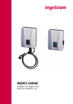
Ingerev V.E. Charging Station
Installation and user manual
ABA2000IKI01_D
11/2012
Ingeteam Power Technology, S.A.
Energy
Avda. Ciudad de la Innovación, 13
31621 SARRIGUREN (Navarra) - Spain
Tel.: +34 948 28 80 00
Fax.: +34 948 28 80 01
e-mail: [email protected]
Service Call Center: +34 948 698 715
The copy, distribution or use of this document or of its content requires written authorisation. Any breach thereof will be reported for
damages. All rights reserved including those of patent rights or design registration.
The conformity of the document content with the hardware described has been checked. However, discrepancies may exist. Liability
will not be assumed for total concordance. The information contained in this document is regularly reviewed and it is possible that there
may be changes in subsequent editions. Other functions may be available which are not covered by this document.
This document may be changed.
Installation and user manual
Ingeteam
Important safety precautions
This manual contains important instructions concerning the installation, handling and use of Ingerev model
ABA7001 Electric Vehicle Charging Stations.
General warnings
The entire manual must be read and understood in full prior to manipulating, installing or operating
the unit.
Keep this manual for later reference.
All applicable safety-related legislation for electrical work must be complied with. Danger of electric
shock.
The operations described in the manual may be performed only by qualified personnel.
The status of qualified personnel referred to in this manual will be, as a minimum, that which meets
all the standards, regulations and laws regarding safety applicable to the tasks of installing and operating this unit.
The responsibility for designating qualified personnel will always fall to the company to which the
personnel belong. It is necessary to decide which workers are suitable or not for carrying out specific
work to preserve their safety at the same time as complying with occupational safety legislation.
These companies are responsible for providing appropriate training in electrical equipment to their
personnel and for familiarising them with the contents of this manual.
Opening the housing does not necessarily mean there is no voltage inside.
Only qualified personnel may open it, following the instructions in this manual.
Compliance with the safety instructions set out in this manual or in the suggested legislation does
not imply exemption from other specific standards for the installation, place, country or other circumstances that affect the unit.
Category II measuring instruments must be used for checking for the absence of voltage.
Ingeteam accepts no liability for any damages caused by improper use of the equipment.
Following is a list of the basic obligatory safety standards for each country:
ABA2000IKI01
•
RD 614/2001 in Spain.
•
CEI 11-27 in Italy.
•
DIN VDE 0105-100 and DIN VDE 1000-10 in Germany.
•
UTE C15-400 in France.
3
Ingeteam
Installation and user manual
Carry out all control and handling without voltage.
As a minimum security measure in this operation, the so-called five golden rules should always be
followed:
1.
Disconnect.
2.
Prevent any possible resupply.
3.
Check there is no voltage.
4.
Ground and short circuit.
5.
Protect from live elements, if any, and put up safety signs around the work zone.
Until these five steps are completed, the work area cannot be considered voltage-free and any work
performed will be considered to be work on live equipment.
Potential hazards for people
Bear in mind the following warnings concerning personal safety.
DANGER: Crushing and joint injuries.
Always follow the indications in the manual on moving and placing the unit.
The weight of this unit can cause injury if not handled correctly.
Potential hazards for the equipment
Bear in mind the following warnings for the protection of your equipment.
CAUTION: Ventilation.
The unit requires quality air flow while it is operating.
Keeping the unit in the upright position and the inlets free of obstacles is essential for this air flow
to reach the inside.
CAUTION: Electrical damage.
Do not touch boards or electronic components. The most sensitive components can be damaged or
destroyed by static electricity.
CAUTION: Operation.
Do not disconnect or connect any terminal while the unit is operating. Disconnect and check for
absence of voltage first.
Personal protection equipment (PPE)
Use all items comprising the personal protection equipment.
Section “4. Safety instructions” contains references to the use of this equipment depending on the situation.
The standard personal protective equipment is:
4
•
Safety goggles for mechanical hazards.
•
Safety goggles for electrical hazards.
•
Safety footwear.
•
Helmet.
ABA2000IKI01
Installation and user manual
Ingeteam
Table of contents
1. Overview..................................................................................................................................................7
1.1. Equipment description.......................................................................................................................7
1.1.1. Models.....................................................................................................................................7
1.2. Compliance with regulations...............................................................................................................7
1.2.1. CE marking...............................................................................................................................7
2. Equipment description...............................................................................................................................8
2.1. Location...........................................................................................................................................8
2.1.1. Environment..............................................................................................................................8
2.1.2. IP rating...................................................................................................................................8
2.1.3. Ambient temperature.................................................................................................................8
2.1.4. Atmospheric conditions..............................................................................................................8
2.1.5. Contamination class..................................................................................................................8
2.1.6. Support surface and fastening....................................................................................................9
2.2. Environmental characteristics.............................................................................................................9
2.3. Main features.................................................................................................................................10
3. Operating, storage and transport conditions...............................................................................................12
3.1. Equipment reception........................................................................................................................12
3.2. Handling and unpacking..................................................................................................................13
3.3. Storage..........................................................................................................................................13
3.4. Conservation...................................................................................................................................13
3.5. Waste handling...............................................................................................................................14
4. Safety instructions..................................................................................................................................16
4.1. Symbols.........................................................................................................................................16
4.2. General safety precautions...............................................................................................................16
4.3. General..........................................................................................................................................17
4.3.1. General risks existing and preventive measures...........................................................................17
4.3.2. Additional risks and measures in handling tasks........................................................................18
4.4. Type of tasks to be carried out..........................................................................................................18
4.4.1. Inspection tasks......................................................................................................................18
4.4.2. Control tasks..........................................................................................................................18
4.4.3. Handling tasks........................................................................................................................18
4.4.4. Personal Protection Equipment (PPE)........................................................................................19
5. Installation.............................................................................................................................................20
5.1. General requirements for installation.................................................................................................20
5.2. Ingerev Garage..........................................................................................................................20
5.2.1. Fixing the unit.........................................................................................................................20
5.2.2. Electrical connection...............................................................................................................21
5.3. Ingerev CITY (wall).......................................................................................................................25
5.3.1. Fixing the unit.........................................................................................................................25
5.3.2. Electrical connection...............................................................................................................26
5.4. Ingerev CITY (floor)......................................................................................................................30
5.4.1. Fixing the unit.........................................................................................................................30
5.4.2. Electrical connection...............................................................................................................31
5.5. Data bus........................................................................................................................................33
6. Operation...............................................................................................................................................35
6.1. Status indication.............................................................................................................................35
6.2. Charging process............................................................................................................................36
6.2.1. Ingerev Garage..................................................................................................................36
Immediate charge.........................................................................................................................36
Deferred charge...........................................................................................................................38
Loss of power supply (immediate charge and deferred charge)...........................................................39
6.2.2. Ingerev City (wall and floor).................................................................................................40
6.3. Languages......................................................................................................................................42
6.4. Incidence/Alarms............................................................................................................................42
6.5. Station shutdown............................................................................................................................42
7. Preventive maintenance........................................................................................................................... 44
ABA2000IKI01
5
Ingeteam
Installation and user manual
7.1. Differential current devices.............................................................................................................. 44
7.2. Grounding...................................................................................................................................... 44
7.3. Air filters....................................................................................................................................... 44
6
ABA2000IKI01
Installation and user manual
Ingeteam
1. Overview
The purpose of this manual is to describe the Ingerev Electric Vehicle Charging Stations and provide information
concerning its correct reception, installation, commissioning, maintenance and operation.
1.1. Equipment description
1.1.1. Models
The main models in the Ingerev range are:
Ingerev Garage
Ingerev City (wall)
Ingerev City (floor)
1.2. Compliance with regulations
1.2.1. CE marking
CE marking is mandatory for the sale of any product within the European Union, without prejudice to standards or
laws. Ingerev units have CE marking by virtue of their compliance with the following directives:
•
Low Voltage Directive 2006/95/EC.
•
Electromagnetic Compatibility Directive 2004/108/EC.
To comply with each directive, compliance with the parts applicable to our units of the appropriate harmonised standards is sufficient.
Low Voltage Directive
Ingerev units comply with this directive by means of compliance with the applicable parts of harmonised standard
EN 61851 Electric Vehicle Conductive Charging System.
Electromagnetic Compatibility Directive
Ingerev units comply with this directive by means of compliance with the applicable parts of harmonised standards:
•
EN 61000-6-2 Electromagnetic Compatibility. Part 6-1: Generic standards - Immunity for residential,
commercial and light-industrial environments.
•
EN 61000-6-3 Electromagnetic Compatibility. Part 6-3: Generic standards - Emission for residential,
commercial and light-industrial environments.
ABA2000IKI01
7
Ingeteam
Installation and user manual
Compliance with these standards calls for compliance with limits and procedures in other standards of the same
series.
2. Equipment description
2.1. Location
The Ingerev units must be installed in environments with specific characteristics.
Guidelines are provided in this section for choosing a suitable environment and adapting the unit to it properly.
2.1.1. Environment
CAUTION
Install the units in a location accessible for installation and maintenance.
CAUTION
Avoid corrosive environments that may affect the proper operation of the unit.
2.1.2. IP rating
Ingerev Garage
Ingerev Garage units have an IP44 level of protection against external agents.
This unit is designed for indoor use.
Ingerev City
Ingerev City units have a IP55 level of protection against external agents.
This unit is designed for indoor and outdoor use.
2.1.3. Ambient temperature
Ingerev Garage
These units are designed to operate in a temperature range from -25 °C to 40 °C.
Ingerev City
These units are designed to operate in a temperature range from -25 °C to 40 °C.
2.1.4. Atmospheric conditions
The ambient air must be clean and relative humidity must be between 5% and 95%.
It should be borne in mind that moderate condensation may occasionally occur as a consequence of temperature
variations. For this reason, apart from the unit's own protection, vigilance of these units is necessary once they have
been started up on sites where the conditions described above are not expected to be present.
In the event of condensation, never apply voltage to the unit.
2.1.5. Contamination class
Ingerev Garage
The pollution class for which the units have been designed is grade PD2.
8
ABA2000IKI01
Installation and user manual
Ingeteam
Ingerev City
The pollution class for which the units have been designed is PD3.
2.1.6. Support surface and fastening
The surface on which the unit is mounted, either on the floor or a wall, should be firm enough to support its weight.
Note the weight of the equipment specified in paragraph “2.3. Main features” to assess the suitability of the anchoring
surface.
2.2. Environmental characteristics
The environmental conditions for operation are:
Ambient conditions
Ingerev Garage
Ingerev City
Minimum temperature
-25 °C
-25 °C
Minimum surrounding air temperature
-25 °C
-25 °C
Minimum surrounding air temperature
40 °C
40 °C
Maximum relative humidity without condensation
95%
95%
For further information see Chapter “3. Operating, storage and transport conditions”.
ABA2000IKI01
9
Ingeteam
Installation and user manual
2.3. Main features
Ingerev Garage
Equipment
Model
Ingerev Garage
WM3
IEC 61851 charging modes
Modes 1 and 2
Mode 3
Variant
Power supply
Maximum Current (A)
Single phase 230 V / 50 Hz (2P+T)
16
Current outlets
Plug mode 1 (Schuko) CEE 7/4 Type F
60309-2 2P+T 16 A
60309-2 3P+N+T 32 A
IEC 62196-2 Type 2
Max. output power (kW)
IEC 61851 connection type
Operating temperature
Relative humidity
3.7
Connection case B
-25 °C to 40 °C
< 95%
Protections
Overcurrents
Differential current
Overvoltages
Energy measurement
RFID reader
Communications
Thermomagnetic circuit breaker with automatic reset*
30 mA Class A with automatic reset*
Class II (optional)
Class A active / Class B reactive
ISO 14443 A / Mifare - 13.56 MHz
RS-485, Ethernet, CAN, GPRS
Environmental protection class
IP44
Anti-tamper protection class
IK08
Directives
Dimensions (H x W x D)
Weight
Low voltage: 2006/95/CE
EMC: 2004/108/CE
480 x 370 x 160 mm
10 kg
Available/ Not available
Note: * Ask about the availability of each model.
10
ABA2000IKI01
Installation and user manual
Ingeteam
Ingerev City
Equipment
Ingerev CITY (floor)
Model
GM1
Ingerev CITY (wall)
GM3
WM1
WM3
IEC 61851 charging modes
Modes 1 and 2
Mode 3
Variant
Maximum Current (A)
16
32
16
3.7
22
3.7/11
32
16
32
16
32
3.7/22
3.7
3.7/22
3.7/11
3.7/22
Single phase 230 V / 50 Hz (2P+T)
Three-phase 400 V / 50 Hz (3P+N+T)
Current outlets
Plug mode 1 (Schuko) CEE 7/4 Type F
60309-2 2P+T 16 A
60309-2 3P+N+T 32 A
IEC 62196-2 Type 2
Max. output power (kW)
IEC 61851 connection type
Connection case B
Operating temperature
-25 °C to 40 °C
Relative humidity
< 95%
Protections
Overcurrents
Differential current
Overvoltages
Thermomagnetic circuit breaker with automatic reset*
30 mA Class A with automatic reset*
Class II (optional)
Energy measurement
RFID reader
Class A active / Class B reactive
ISO 14443 A / Mifare - 13.56 MHz
Communications
RS-485, Ethernet, CAN, GPRS
Environmental protection class
IP55
Anti-tamper protection class
IK10
Low voltage: 2006/95/CE
EMC: 2004/108/CE
Directives
Operating autonomy (no AC supply)
Dimensions (H x W x D)
Weight
1 hour in battery mode
1250 x 255 x 250 mm
757 x 255 x 250 mm
30 kg
18 kg
Available/ Not available
Notes: * Ask about the availability of each model.
ABA2000IKI01
11
Ingeteam
Installation and user manual
3. Operating, storage and transport conditions
CAUTION
Failure to follow the instructions provided in this section may lead to damage to the equipment.
Ingeteam accepts no liability for damage resulting from the failure to follow these instructions.
3.1. Equipment reception
Reception
Upon receipt of the shipment, check the terms specified in the Delivery Note, sign the Signature Receiver Goods field
and return the copy to the return address.
Keep the unit in its packaging until immediately before installation. Maintain the unit upright (Ingerev City) or
horizontal (Ingerev Garage) at all times.
The unit is delivered with the following features:
Model
Weight (kg)
10
600 x 400 x 235
Cardboard box
32
1285 x 265 x 265
19
785 x 265 x 265
Ingerev Garage
Ingerev City (floor)
Length x Depth x Height
(mm)
Packaging
Ingerev City (wall)
Identifying the unit
The serial number of the equipment is its unique identifier. This number must be quoted in any communication with
Ingeteam.
Avda. Ciudad de la Innovación, 13
31621 Sarriguren (Navarra)
[email protected]
Tel 948 288000
Fax 948 288001
Ingerev CITY
Ingerev City WM3 116
Pac
3700 W
Vac
230 Vac
Fac
50 Hz
Iac
16 A
Phases
Single phase
Std
S/N
ABAXXXX
IP55
2011
Location of the name plate for each model.
12
ABA2000IKI01
Installation and user manual
Ingeteam
Transport damage
If the equipment has been damaged during transport, proceed as follows:
1.
Do not proceed with the installation.
2.
Notify the distributor immediately within 5 days of receipt of the equipment.
If ultimately the unit has to be returned to the manufacturer, you must use the same original packaging.
3.2. Handling and unpacking
Correct handling of the units is vitally important in order to:
•
Prevent damage to the packaging which enables them to be kept in optimum condition from shipping until
they are unpacked.
•
Avoid knocks and/or falls which may harm their mechanical characteristics, e.g. cause incorrect closure of
doors, loss of IP rating, etc.
•
Avoid, as far as possible, vibrations which may cause subsequent malfunction.
If you observe any anomaly, please contact Ingeteam immediately.
Separating the packaging
All the packaging can be delivered to a non-hazardous waste management company.
In any event, each part of the packaging may be recycled as follows:
•
Plastic (polystyrene, bag and bubble wrap): the appropriate container.
•
Cardboard: the appropriate container.
3.3. Storage
If the unit is not installed immediately after receipt, the following points should be taken into account in order to
prevent damage:
•
Store the package upright (Ingerev City) or horizontal (Ingerev Garage).
•
Keep the unit free of dirt (dust, shavings, grease, etc) and away from rodents.
•
Keep away from water splashes, welding sparks, etc.
•
Cover the unit with a breathable protective material in order to prevent condensation due to ambient humidity.
•
Units in storage must not be subjected to climate conditions other than those indicated in Section “2.2.
Environmental characteristics”
•
It is very important to protect the unit from chemical products which can cause corrosion, as well as from
salty atmospheres.
•
Do not store the unit outdoors.
Ingerev City models include a battery which, due to its internal charge, should not be without a
power supply for more than 6 months.
Once this period of time has passed after its purchase, Ingeteam accepts no liability for its state.
3.4. Conservation
In order to permit correct conservation of the units, they must not be removed from their original packaging until it
is time to install them.
In case of prolonged storage, the use of dry places avoiding, as far as possible, sharp changes in temperature is
recommended.
Deterioration of the packaging (tears, holes, etc.) prevents the units from being kept in optimum conditions before
installation. Ingeteam accepts no liability for inconvenience or damage arising in the case of failing to observe this
condition.
ABA2000IKI01
13
Ingeteam
Installation and user manual
3.5. Waste handling
During the various processes for installation, start-up and maintenance, waste is generated which must be handled
appropriately according to the regulations in the corresponding country.
At the end of the unit's life, the waste must be processed by an authorised waste management company.
Ingeteam, in accordance with its policy of respect for the environment, will inform the authorised manager, via this
Section, of the location of components to be decontaminated.
The elements within the unit that must be handled individually are:
1.
Liquid crystal displays.
2.
Batteries or accumulators.
3.
Printed circuit cards.
Their location is shown in the following images.
1
3
2
Waste that can be handled by conventional waste collection means
Most of this waste is from the unit’s packaging, which must be properly separated and processed.
14
ABA2000IKI01
Installation and user manual
Ingeteam
All the packaging can be delivered to a non-hazardous waste management company.
In any event, each part of the packaging may be recycled as follows:
•
Plastic (polystyrene, bag and bubble wrap): Appropriate container (plastic and bottles).
•
Cardboard: Appropriate container (paper and cardboard).
ABA2000IKI01
15
Ingeteam
Installation and user manual
4. Safety instructions
This section contains safety instructions which must be followed when installing, operating and accessing the unit.
Failure to comply with the “Safety instructions” may cause injury or even death or cause damage to the unit.
Read the “Safety instructions” carefully before working on the unit.
4.1. Symbols
The warnings advise of conditions which may cause serious injury or death and/or damage to the equipment. The
means of avoiding the hazard to both people and the unit is indicated along with the warning.
The symbols and an explanation of their meaning can be seen below.
DANGER: High voltage
High voltage warning: Warns of high voltage which can cause injury or even death and/or damage to
the equipment
General warning. Warns of conditions which can cause injury and/or damage to the equipment.
Please read this information carefully as it is written for your personal safety and to ensure the longest possible service
life for the unit.
4.2. General safety precautions
Installation, start-up, inspection and maintenance operations may only be carried out by personnel
appropriately qualified and trained in electrical subjects (hereinafter qualified personnel). You are
reminded of the obligation to comply with safety regulations applicable to electrical work.
Opening the housings in no way implies the absence of voltage, and only qualified personnel following
the safety guidelines described in this document may access the compartments.
The set of conditions listed below should be considered as minimum requirements. It is always preferable to shut off the main power supply. Installation defects may result in unwanted feedback. Danger
of electric shock.
In addition to the safety measures indicated in this manual, the general measures that apply in this
area (specific to the installation, country, etc.) must be taken into account.
The electrical installation must not involve a risk of fire or explosion. Workers must be duly protected
against accident risks from direct or indirect contact. The electrical installation and protection devices
must take the voltage, the external determining factors and the competence of the people who have
access to parts of the installation into account.
In compliance with basic safety legislation, all equipment must be appropriate to protect exposed
workers against the risk of direct or indirect contacts. In any case, the electrical parts of the work
equipment must comply with that laid down in the corresponding specific regulations.
16
ABA2000IKI01
Installation and user manual
Ingeteam
In compliance with Electric Risk basic legislation, all workers who carry out work outdoors will suspend
their work in the case of storms, rain or strong winds, snow or any other unfavourable environmental
condition which makes visibility or handling tools difficult. Work on installations directly connected to
overhead electricity lines must be disconnected in the case of storms.
Ingeteam accepts no liability for any damages caused by improper use of the equipment. Any work
carried out on any equipment which implies a modification of the original electrical arrangements
must be proposed in advance to Ingeteam. These must be studied and approved by Ingeteam.
The necessary means must be arranged to prevent people from outside the installation approaching
or handling the equipment.
These instructions must be easily accessible close to the unit and located within reach of all users.
Before installation and start-up, please read these safety instructions and warnings carefully as well
as all the notices located on the unit. Ensure that all the notices are perfectly legible and that those
which are damaged or have disappeared are restored.
4.3. General
This section defines the preventive measures to take to carry out all types of tasks on the unit, working safely and
controlling risks which cannot be avoided.
Protection against direct contact is by means of the housing, which has IP20 protection class.
The unit has been tested according to the applicable regulations to comply with the safety requirements, the values
for insulation distances and leakage paths for the voltages used.
The tools and/or equipment used in handling tasks must as a minimum have double reinforced insulation (Class II).
4.3.1. General risks existing and preventive measures
Impact against immovable objects
•
Inform workers of the risk
•
Adequate lighting
•
Work with care
Knocks, punctures and cuts from objects and/or tools
•
Keep the cover closed if not working on the equipment
•
Adequate lighting
•
Order and cleanliness
•
Mandatory use of hard hat, safety footwear and gloves when necessary.
ABA2000IKI01
17
Ingeteam
Installation and user manual
Electrical risk
•
Follow the instructions in the section on PPE and “4.2. General safety precautions”
•
Inform the worker of the risk
•
Comply with R.D.614/2001 and REBT.
4.3.2. Additional risks and measures in handling tasks
Thermal contact
•
Inform workers of the risk
•
Recommended use of gloves
•
Disconnect the power and wait 10 minutes for the hot parts inside the unit to cool down.
4.4. Type of tasks to be carried out
The preventive maintenance tasks for the electrical panels involve Inspection, Control and Handling actions, depending
on the case.
Accessing the housing through any other cubicle other than that described in this manual is strictly prohibited.
To open any of the covers of the enclosure (side, rear, top or door) the main power supply outside of the box must be
switched off.
4.4.1. Inspection tasks
Definition: Involves opening the enclosure for visual inspection tasks.
4.4.2. Control tasks
Definition: Tasks relating to software, voltage checks at safe measuring points, etc.
Preventive maintenance tasks of the unit, carried out from the man-machine interface.
Control tasks related to testing and changing circuit breaker settings, under no circumstances will the any part thereof
(terminals, cables, protections) be accessed or subject to control tasks during this operation, except to the specific
control to verify and/or modify the settings.
4.4.3. Handling tasks
Definition: Tasks relating to component installation and/or replacement. Any task that does not fall under Inspection
or Control is considered Handling.
It is always necessary to first disconnect and check for absence of voltage.
The “5 Golden Rules” must be adhered to.
18
ABA2000IKI01
Installation and user manual
Ingeteam
5 GOLDEN RULES
1.
Disconnect
Switching on the possible voltage sources. Bear in mind that any capacitors or other elements powered
from uninterruptible power supplies are still live.
2.
Prevent any possible feedback.
The switching devices used to switch off the equipment must be protected against any possible
disconnection.
3.
Check there is no voltage.
Check that there is no voltage in all the active elements of the electrical system or as close as possible
to the work area.
4.
Ground and short circuit.
In the low voltage installations that by induction or for other reasons may be accidentally live.
5.
Rope off and mark the work area.
4.4.4. Personal Protection Equipment (PPE)
Inspection
The use of safety footwear to standard EN 345-1:1992 is mandatory and work clothing should be cotton and be free
of conductor/metallic elements.
Control
The use of helmets compliant with standard EN 397:1995 and safety footwear compliant with standard EN 345-1:1992
is mandatory. The use of standard safety gloves is also mandatory for voltage-free tasks.
It is also mandatory to use dielectric gloves meeting standard EN-60903-1992 and protective face mask against
electric shock for voltage testing tasks and opening or closing automatic switches under load.
Handling
The use of helmets compliant with standard EN 397:1995 and safety footwear compliant with standard EN 345-1:1992
is mandatory.
It is also mandatory to use dielectric gloves meeting standard EN-60903-1992 and protective face mask against
electric shock for voltage testing tasks and opening or closing automatic switches under load.
ABA2000IKI01
19
Ingeteam
Installation and user manual
5. Installation
Before installing the unit, the packaging must be removed, taking special care not to damage the housing.
Check that there is no moisture inside the packaging. If there are signs of moisture, the unit must not be installed
until you are sure it is completely dry.
All installation operations must comply with current regulations.
5.1. General requirements for installation
Ventilation and the space for work, which must be suitable for maintenance tasks according to current regulations.
The external connection devices, which must be suitable and sufficiently close as set forth in current regulations.
The connecting cables must be of the appropriate section for the maximum current.
Special care must be taken to ensure that there are no external elements near the air inlets and outlets to obstruct
proper ventilation of the unit.
5.2. Ingerev Garage
1. Together with the unit you will find a full-size paper
drilling template to mark the holes on the wall needed
for mounting the equipment. After you have marked the
points on the wall, proceed to drill the holes.
98
5.2.1. Fixing the unit
46,8
133
133
46,8
378
Ø6
Template
20
ABA2000IKI01
Installation and user manual
Ingeteam
2. To mount the Ingerev Garage unit a bracket must be fastened to the wall with three screws. Then hang
the unit on the support fixture.
3. Once the wall bracket in in place, it is fully anchored with a screw through the hole for this purpose at the
bottom of the station.
4.
Check that the unit is properly secured.
5.2.2. Electrical connection
Once the unit has been mounted in its final position and has been solidly secured, make the electrical connections
to it.
Wiring must be carried out by qualified technical personnel.
Care must be taken to ensure the equipment is not live when accessing its interior.
When checking that there is no voltage, wearing dielectric gloves and safety goggles approved for
electrical hazards is required.
ABA2000IKI01
21
Ingeteam
1.
Installation and user manual
To proceed with connection, you must open the unit by removing the 4 screws shown in the figure below.
2. Once the unit is open, proceed with the electrical connection. Connect the feed cables to the terminals as
shown in the figure below:
T L N
•
T: Ground
•
L: Live
•
N: Neutral
The supply connection must meet certain requirements:
Supply connection specification
Connection type
Single phase
Number of wires
2P + T
Rated current
Maximum wire diameter
22
16 A
10 mm (2 x 6 mm2)
2
ABA2000IKI01
Installation and user manual
Ingeteam
3. Once the above steps have been completed, proceed to feed the charging station, for which the differential
and breaker protection must be switched ON (up):
Thermomagnetic circuit breaker
for Mode 1 (Schucko)
ON
ON
ON
ON
OFF
OFF
OFF
OFF
Thermomagnetic circuit breaker
for Mode 3 with activation coil
Differential circuit breaker
Optionally, the station can be equipped with a self-resetting differential protection block. In this case the differential
protection must be turned on (turn the switch up to ON) and then slide the tab to the left as shown in the figure.
ON
OFF
A
A
CLACK!
A
4.
Once the connections have been made, close the unit with the tamper-proof Torx screws mentioned above.
ABA2000IKI01
23
Ingeteam
Installation and user manual
5. When the charging station is powered up for two seconds it will light up in red, blue and green. After a brief
status verification, the light will turn green and the display will show an electric vehicle and the current time. The
station is ready and awaits user ID to begin charging.
If the station identifies an operation fault, the light would turn red and the display would show the type of fault (see
section “6. Operation”).
24
ABA2000IKI01
Installation and user manual
Ingeteam
5.3. Ingerev CITY (wall)
5.3.1. Fixing the unit
74
110
74
41,5
396
5
O6,5
,
O6
O6
,5
155
1. Together with the unit you will find a full-size paper drilling template
to mark the holes on the wall needed for mounting the equipment. After
you have marked the points on the wall, proceed to drill the holes.
O5
165
O5
71
110
71
Template
2. To mount the Ingerev City unit (wall-mounted) you must first fasten a bracket to the wall with three
screws, as seen in the figure below.
3. Once hung on the wall bracket, you must open the front enclosure. The side lock will open with the key
supplied.
ABA2000IKI01
25
Ingeteam
Installation and user manual
4. Upon opening the enclosure you will find that the ribbon cable is loose as a security measure to avoid pulling
on the internal components.
5. Finish installing the station by inserting the two screws from the inside into the wall. You will see two plastic
caps on the holes for that purpose. Remove them and proceed to insert the screws.
covers
6.
screws
Check that the unit is properly secured.
5.3.2. Electrical connection
Once the unit has been mounted in its final position and has been solidly secured, make the electrical connections
to it.
Wiring must be carried out by qualified technical personnel.
Care must be taken to ensure the equipment is not live when accessing its interior.
26
ABA2000IKI01
Installation and user manual
Ingeteam
When checking that there is no voltage, wearing dielectric gloves and safety goggles approved for
electrical hazards is required.
1. With the front door still open, open the metal plate which houses the electronic card to access the feed
terminal block.
Plate
T: Ground
T L N
L: Live
N: Neutral
Terminal strip details
Plate opening
The supply connection must meet certain requirements:
Supply connection specification
Connection type
Single phase
Three-phase
Number of wires
2P + T
3P + N + T
Rated current
Maximum wire diameter
ABA2000IKI01
16 A
Up to 32 A
10 mm2 (2 x 6 mm2)
27
Ingeteam
2.
Installation and user manual
Switch the differential and breaker protection ON (up):
ON
OFF
ON
OFF
Optionally, the station can be equipped with a self-resetting differential protection block. In this case the differential
protection must be turned on (turn the switch up to ON) and then slide the tab to the left as shown in the figure.
ON
OFF
A
A
CLACK!
A
3.
28
Close the metal plate where the electronic card is stored.
ABA2000IKI01
Installation and user manual
Ingeteam
Plate
Once the connection has been made, proceed to connect the ribbon cable from the display as shown in the image
below:
4.
You may then proceed to close the charging station using the lock on the top right.
5. When the charging station is powered up for two seconds it will light up in red, blue and green. After a brief
status verification, the light will turn green and the display will show an electric vehicle and the current time. The
station is ready and awaits user ID to begin charging.
If the station identifies an operation fault, the light would turn red and the display would show the type of fault “6.
Operation”.
ABA2000IKI01
29
Ingeteam
Installation and user manual
5.4. Ingerev CITY (floor)
5.4.1. Fixing the unit
1.
Open the back enclosure by removing the 8 T30-type Torx tamper-proof screws.
2. Proceed to fastening the unit to the ground by using a clamping plate, supplied by Ingeteam, such as the
plate shown in the figure below.
30
ABA2000IKI01
Installation and user manual
Ingeteam
The connection hose or cable must be passed through the rectangular tube to later connect the station to the mains.
A trim unit is available, provided by Ingeteam, which must be placed between the bolts or studs and the M12 nuts
anchoring the charging station to them.
3.
Check that the unit is properly secured.
5.4.2. Electrical connection
Once the unit has been mounted in its final position and has been solidly secured, make the electrical connections
to it.
Wiring must be carried out by qualified technical personnel.
Care must be taken to ensure the equipment is not live when accessing its interior.
When checking that there is no voltage, wearing dielectric gloves and safety goggles approved for
electrical hazards is required.
1. With the back enclosure open, as stated in the previous section, proceed to connect the feed cables to the
terminal strip as shown in the figure below:
T L N
T: Ground
L: Live
N: Neutral
ABA2000IKI01
31
Ingeteam
Installation and user manual
The supply connection must meet certain requirements:
Supply connection specification
Connection type
Single phase
Number of wires
2P + T
Rated current
16 A
10 mm2 (2 x 6 mm2)
Maximum wire diameter
2.
Switch the differential and breaker protection ON (up):
ON
ON
OFF
OFF
Optionally, the station can be equipped with a self-resetting differential protection block. In this case the differential
protection must be turned on (turn the switch up to ON) and then slide the tab to the left as shown in the figure.
ON
OFF
C
C
CLACK!
C
32
ABA2000IKI01
Installation and user manual
3.
Ingeteam
Close the back enclosure by screwing in the 8 T30-type Torx tamper-proof screws.
4. When the charging station is powered up for two seconds it will light up in red, blue and green. After a brief
status verification, the light will turn green and the display will show an electric vehicle and the current time. The
station is ready and awaits user ID to begin charging.
If the station identifies an operation fault, the light would turn red and the display would show the type of fault (see
section “6. Operation”).
5.5. Data bus
All Ingerev charging stations include a local RS485 data bus. This data bus can be used both to extract local data
with the Ingecon Sun Manager software provided by and to for various charging stations to communicate between
themselves. In the latter case, the bus configuration allows access both locally and remotely to the data of each and
every one of the charging stations that are connected to each other. In other words, it allows communication between
all charging stations that are part of the installation using a single communications channel or modem.
ABA2000IKI01
33
Ingeteam
Installation and user manual
A maximum of 10 units can be connected to each other; any one of those which are located at the ends of the data
bus may be the charging station fitted with a modem.
The RS-485 data bus is fitted with end-of-line jumpers in each of the control cards.
If you wish to have charging stations communicate with each other, the jumper must be removed from
all the intermediate stations, so that it remains only at the end ones.
If one of the stations is fitted with a modem, the end-of-line jumper must also be removed from this
station.
Jumper to be removed
34
ABA2000IKI01
Installation and user manual
Ingeteam
6. Operation
The main function of the charging station is to supply and measure power for users previously authorized via an RFID
card reader.
6.1. Status indication
The charging station shows its status on multi-LED display. The location of these LEDs will vary by model.
LEDs
LED locations.
Ingerev Garage
Status
Lighting
Description
Waiting for vehicle
Steady green
The charging station is waiting for a vehicle to be plugged in for charging.
Waiting to charge
Flashing green
A user has held the card over the reader and the charging station is waiting
for a vehicle to be plugged in.
Charging
Steady green
A vehicle has been plugged into the charging station. Only the green LED
located at the top of the selected plug will light up.
Low current
Flashing green
Reduced current.
Charging ended
Flashing green
After charging, the user has held the card and the charging station is in
standby for the vehicle to be unplugged.
Error
Steady red
The charging process is not occurring properly due to some problem.
Fault
Steady red
The charging station is not operating correctly.
Stand-by
None
The charging station has been disconnected remotely.
ABA2000IKI01
35
Ingeteam
Installation and user manual
Ingerev City
Status
Lighting
Description
Waiting for vehicle
Green
The charging station is waiting for a vehicle to be plugged in for charging.
Waiting to charge
Flashing yellow
A user has held the card over the reader and the charging station is waiting
for a vehicle to be plugged in.
Charging
Steady blue
A vehicle has been plugged into the charging station.
Low current
Flashing blue
Reduced current.
Charging ended
Flashing yellow
After charging, the user has held the card and the charging station is in
standby for the vehicle to be unplugged.
Error
Steady red
The charging process is not occurring properly due to some problem.
Fault
Steady red
The charging station is not operating correctly.
Stand-by
None
The charging station has been disconnected remotely.
6.2. Charging process
6.2.1. Ingerev Garage
The power plug should not be removed from the vehicle while it is being charged.
The station includes a display+keyboard unit preset for accessing the
different menus comprising its firmware.
The following points describe the proceedings for starting and finishing
the charging process.
There are two charging options:
•
Immediate charge.
•
Deferred charge (this option has to be activated in the station for
it to be available).
The charging process is slightly different depending on the option selected.
Read this information carefully and in case of doubt consult Ingeteam
Customer Service.
Immediate charge
When this option for charging the vehicle is selected, the station starts charging the vehicle immediately after it is
connected to it.
Start of charging process
1.
Make sure the station is in waiting for vehicle status, with the following two screens being displayed alternately:
2. Press
to access the language selection menu for the charging session. After the charging process, the
language will revert to the station default.
36
ABA2000IKI01
Installation and user manual
LANGUAGE
ENGLISH
Ingeteam
After accessing the language selection menu, navigate
between the various options by pressing
and
.
Highlight the desired language and press
.
3. Hold the card over the reader under the display. When the station recognizes the card correctly, a menu for
selecting the charge or for cancellation is displayed.
SELECT OPTION
IMMEDIATE CHARGE
Press
options.
and
to navigate between the various
When the option immediate charge is highlighted, press
.
The option deferred charge will only appear if it is activated
at the station.
4.
A screen with a flashing plug is displayed. Connect the cable into the appropriate outlet.
If the power plug selected is the mode 3 plug, the station automatically detects the connection and continues the
charging sequence stipulated by the IEC61851 standard.
If the power plug selected is the mode 1 plug (Schuko), the station automatically detects the connection after a predefined delay and continues the charging sequence stipulated by the IEC61851 standard.
The station does not allow and is not designed for simultaneous use of both power outlets. Only the
selected outlet remains active.
ABA2000IKI01
37
Ingeteam
Installation and user manual
5. After connecting the vehicle to the station, the following screen is shown to indicate that the charging
process has started correctly.
CHARGING
End of charging process
6. To conclude the charge cycle, hold the card over the reader again. The station disconnects the power supply
and unlocks plug mode 3 if that is the one being used.
7.
Pull the plug out
The station will go back to “awaiting vehicle” status.
Deferred charge
For linked points the option of a deferred charging process is available. In order to be able select this type of charging,
the deferred charge option must be activated in the station.
The selected starting time of the charging process can be modified by the user later on.
The charging process is identical to the immediate charge scheme, except in the following respects:
Start of charging process
1.
Make sure the station is in waiting for vehicle status, with the following two screens being displayed alternately:
2. Press
to access the language selection menu for the charging session. After the charging process, the
language will revert to the station default.
LANGUAGE
ENGLISH
After accessing the language selection menu, navigate
between the various options by pressing
and
.
Highlight the desired language and press
.
3. Hold the card over the reader under the display. When the station recognizes the card correctly, a menu for
selecting the charge or for cancellation is displayed.
38
ABA2000IKI01
Installation and user manual
Ingeteam
Press
options.
SELECT OPTION
to navigate between the various
When the option Deferred Charge is highlighted, press
.
DEFERRED CHARGE
4.
and
A screen with a flashing plug is displayed. Connect the cable into the appropriate outlet.
5. Once the vehicle is connected to the station, the time selection screen for deferred charging is displayed. The
time displayed is saved on the card as predefined, but it is possible to modify it to any desired time.
SELECT STARTING TIME
21
The screen for the time selection of the deferred charge shows the starting time, highlighted over black background.
Press the
button to return to the option selection menu. To modify the time, press the buttons
and
until you have reached the desired time. Press
to change to minutes and select them, proceeding the same way
as in the case of hours and, when finished, press
to change to seconds. After selecting them, press
again.
The following informative screen will be displayed:
Charging will begin at the selected starting time.
CHARGING
6. At the time set for beginning charging the following screen is shown to indicate that the charging process
has started correctly.
CHARGING
End of charging process
7. To conclude the charge cycle, hold the card over the reader again. The station disconnects the power supply
and unlocks plug mode 3 if that is the one being used.
8.
Pull the plug out.
The station will go back to “awaiting vehicle” status.
Loss of power supply (immediate charge and deferred charge)
If the charging station loses power during the charging process, it automatically unlocks the mode 3 plug, if this has
been the mode selected, and it remains inactive until the supply is restored.
Once power is restored, the station automatically restarts and reverts to the status before the loss of power.
ABA2000IKI01
39
Ingeteam
Installation and user manual
6.2.2. Ingerev City (wall and floor)
The power plug should not be removed from the vehicle while it is being charged.
Start of charging process
1.
Make sure the station is in waiting for vehicle status, with the electric vehicle icon shown on the display.
2.
Hold the card close to the card reader located below the display.
If the card is read correctly, the charging station goes into “awaiting charge” status. The display will show a flashing
plug icon.
3.
40
Lift the cover manually and plug the cord into the appropriate electrical outlet.
ABA2000IKI01
Installation and user manual
Ingeteam
If the power plug selected is the mode 3 plug, the station automatically detects the connection and continues the
charging sequence stipulated by the IEC61851standard.
If the power plug selected is the mode 1 plug (Schuko), position the cable so that it comes out of the hole in the
bottom centre of the socket, allowing the cover to close shut. The station automatically detects the connection and
continues to charge once the cover is tightly shut.
The station does not allow and is not designed for simultaneous use of both power outlets. Only the
selected outlet remains active.
When the cover is closed shut, the station will be blocked and power supply will be switched on, changing the status
to “charge”.
End of charging process
4. To conclude the charge cycle, hold the card over the reader again. The station disconnects the power supply
and unlocks the socket cover or the plug.
5. Open the cover, remove the plug and close the cover. The station will lock the cover and revert to “awaiting
vehicle” status.
Loss of power supply
The station has an auxiliary power supply (Ingerev City models) that allows it to continue basic operation in spite
of power losses. In this situation the unit shows the anomaly on its display.
In the event that the station is in standby in “awaiting vehicle” status and loses power, the message displayed is:
”AC FAILURE”
If the power supply is lost while a vehicle is being charged, the message would be:
”AC FAILURE. Identify again to unlock the door”
In this situation, users would have to hold their ID badge over the reader to unlock the cover and unplug their vehicle.
After this, the station would shut down.
ABA2000IKI01
41
Ingeteam
Installation and user manual
A Master User will be able to unlock the cover to remove the plug and may, after further identification,
turn off the station with guard locking active.
When power is restored after an earlier power loss, the charging station will return to its pre-disconnection status.
6.3. Languages
The information for each user session is displayed in the language set on each card, regardless of the station’s default
language.
The station user may change the default language with a Master card.
Users without a pre-cofnigured language preference will see the information displayed in the station’s default language.
6.4. Incidence/Alarms
In case of fault, the station switches to fault status, indicating the reason on the display:
Installation defect
The station’s protection devices have been triggered.
The station detects that the fault persists and will not proceed to resetting the protections until it is resolved.
The electrical installation must then be inspected by qualified personnel.
Supply failure
•
No electrical grid. No electrical supply. The station re-boots when it is restored.
The protection devices have been triggered. The protection devices have been triggered but the root fault
•
has disappeared.
The station will then reset the protections shortly thereafter.
Energised plug
There is current in the plug when ther should not be.
Notify technical service about the issue.
Power meter communication fault
Internal communication with the energy meter is faulty.
Notify technical service about the issue.
RFID communication fault
Internal communication with the card reader is faulty.
Notify technical service about the issue.
Plug not energised
There is no current in the plug when there should be. Charging is not possible.
Notify technical service about the issue.
If you have any problems with the performance of the station please call the tech support hotline.
6.5. Station shutdown
Ingerev Garage
The station will shut down when the power supply is disconnected.
Ingerev City
If you wish to turn off or uninstall the charging station, disconnecting it from the power supply directly is not sufficient
due to the backup power supply. In this case the station will display the following alarm message:
42
ABA2000IKI01
Installation and user manual
Ingeteam
”AC FAILURE”
To completely turn off the station, a Master-type card should be held over the reader. You may then proceed to fully
disconnect the charging station.
It is strongly recommended to perform a complete shutdown of the charging station to prolong the life
of the auxiliary power supply.
ABA2000IKI01
43
Ingeteam
Installation and user manual
7. Preventive maintenance
7.1. Differential current devices
An annual inspection is recommended for checking the residual current device located inside the station. Press the
reset button on the device and wait for the reset.
When opening the back cover (for the sole purpose of testing both differential current devices), avoid
contact with any other device or cable at all times.
The worker who accesses the bottom of the access door to the protection devices must be properly
trained and authorised by the employer (the charging station operator) to perform these tasks.
7.2. Grounding
An annual inspection is recommended for checking the proper connection of the metal housing and other metal
components located outside the charging station to the unit’s ground installation.
The back cover is opened for the sole reason of performing a continuity test between the arrival of the
ground conductor from the installation and the metal housing and other metal components located
outside of the charging station.
The worker who accesses the bottom of the access door to the protection devices must be properly
trained and authorised by the employer (the charging station operator) to perform these tasks.
7.3. Air filters
We recommend an annual inspection of the air filters located in the the charging station’s vents.
44
ABA2000IKI01
Notes
Notes
Notes
Ingeteam Power Technology, S.A.
Energy
Avda. Ciudad de la Innovación, 13
31621 SARRIGUREN (Navarre) - Spain
Tel.: +34 948 28 80 00
Fax: +34 948 28 80 01
e-mail: [email protected]
ABA2000IKI01_D
11/2012
Ingeteam S.r.l.
Via Emilia Ponente, 232
48014 CASTEL BOLOGNESE (RA) - Italy
Tel.: +39 0546 651 490
Fax: +39 054 665 5391
e-mail: [email protected]
Ingeteam GmbH
DE-153762639
Herzog-Heinrich-Str. 10
80336 MÜNCHEN - Germany
Tel.: +49 89 99 65 38 0
Fax: +49 89 99 65 38 99
e-mail: [email protected]
Ingeteam SAS
Parc Innopole
BP 87635 - 3 rue Carmin - Le Naurouze B5
F- 31676 Toulouse Labège cedex - France
Tel.: +33 (0)5 61 25 00 00
Fax: +33 (0)5 61 25 00 11
e-mail: [email protected]
Ingeteam INC.
5201 Great American Parkway, Suite 320
SANTA CLARA, CA 95054 - USA
Tel.: +1 (415) 450 1869
+1 (415) 450 1870
Fax: +1 (408) 824 1327
e-mail: [email protected]
Ingeteam INC.
3550 W. Canal St.
Milwaukee, WI 53208 - USA
Tel.: +1 (414) 934 4100
Fax: +1 (414) 342 0736
e-mail: [email protected]
Ingeteam, a.s.
Technologická 371/1
70800 OSTRAVA - PUSTKOVEC
Czech Republic
Tel.: +420 59 732 6800
Fax: +420 59 732 6899
e-mail: [email protected]
Ingeteam Shanghai, Co. Ltd.
Shanghai Trade Square, 1105
188 Si Ping Road
200086 SHANGHAI - P.R. China
Tel.: +86 21 65 07 76 36
Fax: +86 21 65 07 76 38
e-mail: [email protected]
Ingeteam Ltda.
Rua Luiz Carlos Brunello, 286
Chácara Sao Bento
13278-074 VALINHOS SP - Brazil
Tel.: +55 19 3037 3773
Fax: +55 19 3037 3774
e-mail: [email protected]
Ingeteam Power Technology, S.A.
www.ingeteam.com