1
Safety Relay Unit
OMRON declares that G9SE series are in conformity with the requirements of the following
EU/EC Directives. If you need a complete Declaration of Conformity, please contact your
Omron representative:
- EMC Directive: 2004/108/EC, 2014/30/EU
- Machinery Directive: 2006/42/EC
Standards
G9SE series are designed and manufactured in accordance with the following standards:
- EN ISO13849-1: 2008 PL e Category 4
- IEC/EN 60947-5-1,
- IEC/EN 62061 SIL3,
- EN81-1
- EN81-2
- UL508
- CAN/CSA C22.2 No.14
- GB14048.5
Precaution for Safe Use
Meanings of Signal Words
The following signal words are used in this manual.
Indicates a potentially hazardous situation which, if not avoided, will
result in minor or moderate injury, or may
WARNING
result in serious injury or death.
Additionally there may be significant property damage.
Meaning of Alert Symbols
The following alert symbols are used in this manual.
Indicates prohibited actions
Indicates mandatory actions
Alert Statements
WARNING
Serious injury may possibly occur due to breakdown of safety outputs.
Do not connect loads beyond the rated value to the safety outputs.
Serious injury may possibly occur due to loss of required safety functions.
Wire G9SE properly so that supply voltages or voltages for loads do NOT touch the
safety inputs accidentally or unintentionally.
Serious injury may possibly occur due to loss of safety functions.
Use appropriate devices referring to the information shown below.
Controlling Devices
Emergency stop switch
Requirements
Use approved devices with Direct Opening Mechanism complying with
IEC/EN 60947-5-1
Door interlocking switch Use approved devices with Direct Opening Mechanism complying with
Limit switch
IEC/EN 60947-5-1 and capable of switching micro loads of 24VDC, 5mA.
Safety Sensor
Use approved devices complying with the relevant product standards,
regulations and rules in the country where it is used.
Relay with forcibly guided Use approved devices with forcibly guided contacts complying with
contacts
EN 50205.
For feedback purpose use devices with contacts capable of switching
micro loads of 24VDC, 5mA.
Contactor
Use contactors with forcibly guided mechanism to input the signal to
Feedback/Reset input of G9SE through the NC contact of the contactor.
For feedback purpose use devices with contacts capable of switching
micro loads of 24VDC, 5mA.
Failure to open contacts of a contactor cannot be detected by monitoring
its auxiliary NC contact without forcibly guided mechanism.
Other devices
Evaluate whether devices used are appropriate to satisfy the requirements
of safety category level.
Precautions for Safe Use
(1) Use G9SE within an enclosure with IP54 protection or higher of IEC/EN60529.
(2) When ready for wiring, the power source shall be disconnected first. Further, at operating this unit, do not touch
the terminals in order to prevent an electrical shock.
(3) Do not apply any excessive voltage or current to the input or output circuit the G9SE. Doing so may result in damage
to the G9SE or cause a fire.
(4) Incorrect wiring may lead to loss of safety function. Wire conductors correctly and verify the operation of G9SE
before commissioning the system in which G9SE is incorporated.
(5) Do not apply DC voltages exceeding the rated voltages, or AC voltages to G9SE.
(6) Use SELV/PELV DC porwer supply satisfying requirements below to prevent electric shock.
- DC power supply with double or reinforced insulation, for example, according to IEC/EN60950 or EN50178 or
a transformer according to IEC/EN61558.
- DC supply satisfies the requirement for class 2 circuits stated in UL 508.
(7) The lifetime of G9SE depends on the conditions of switching of its outputs. Be sure to conduct its test operation
under actual operating conditions in advance and use it within appropriate switching cycles. Apply protection
circuitry against back electromotive force in case connecting inductive loads to safety outputs.
(8) Do not operate the G9SE with flammable or explosive gas. An arc with operation and the heat of relay will cause
a fire or an explosion.
(9) Do not drop G9SE to the ground or dismantle, repair, modify G9SE, otherwise an electric shock may occur or
the G9SE may malfunction. It may lead to loss of its safety functions.
(10) Use protective device (Fuse etc.) for short-circuit protection and ground fault protection, otherwise a fire may occur
or the G9SE may malfunction.
(11) Auxiliary monitoring outputs are NOT safety outputs. Do not use auxiliary outputs as any safety output.
Such incorrect use causes loss of safety function of G9SE and its relevant system.
(12) After installation of G9SE, qualified personnel shall confirm the installation, and shall conduct test
operations and maintenance.
The qualified personnel shall be qualified and authorized to secure the safety on each phases of design,
installation, running, maintenance and disposal of system.
(13) A person in charge, who is familiar to the machine in which G9SE is to be installed, shall conduct and verify
the installation.
0.30.40.5
0.2
0.6
0.1
0.7
0.8
0
1.0
5.0
1.5
4.0
3.0
2.52.0
cutting edge
OFF-DELAY
ex.1) 0 second off-delay setting
0.30.40.5
0.2
0.6
0.1
0.7
0.8
0
1.0
5.0
1.5
4.0
3.0
2.52.0
cutting edge
Type G9SE-401
6DIHW\
,QSXW
5HVHW
)HHGEDFN
,QSXW
$X[LOLDU\
2XWSXW
$ 7 7
OFF-DELAY
;
5HVHW
)HHGEDFN
,QSXW
6DIHW\
,QSXW
5 mA Min.
ON voltage
11 VDC Min.
5 VDC Max.
OFF voltage
OFF current
Maximum cable length
Reset input time
G9SE-401
100 ms Max. (See Note3)
15 ms Max.
兠
兠
Input current
G9SE-221-TƑ
Within plus or minus 10 of
the set value
1 mA Max.
100 m Max.
250 ms Min.
Minimum applicable load
Conditional short-circuit current
(IEC/EN60947-5-1)
6DIHW\
2XWSXWV
LQVWDQWD
QHRXV
$X[LOLDU\
2XWSXW
$ 7 7
;
$ 7 7 7 7 7
5HVHW
)HHGEDFN
,QSXW
6DIHW\
,QSXW
Power Supply
$X[LOLDU\
2XWSXW
24 VDC 4 mA
100 A (See Note5)
Pollution degree
2
Over voltage category (IEC/EN60664-1)
Between input
Impulse
withstand and output
voltage
Between
(IEC/EN
different poles
60947-5-1)
of output
Insulation
Between input
specification
and output
Dielectric
Between
strength
different poles
of output
Insulation resistance
Safety output: Class 䱸䢮䢢䣶䣪䣧䢢䣱䣶䣪䣧䣴䣵䢼䢢Class 䱷䢢
6 kV
6 kV (between 13-14/23-24 and 33-34/43-44(37-38/47-48))
4 kV (between 13-14 and 23-24,
between 33-34(37-38) and 43-44(47-48))
2,200 VDC
1,500 VAC
Vibration resistance (See Note6)
100 MΩ Min.
Frequency:10 to 55 to 10 Hz
Amplitude:0.35 mm half amplitude (0.7 mm double amplitude)
Mechanical
Destruction
shock resistance
Malfunction
(See Note7)
Surrounding Air Temperature
100 m/s
-10 to 55䰳 (No freezing or condensation)
300 m/s
2
2
Ambient humidity
25 to 85RH
Degree of protection
IP20
Weight
approx. 150 g
Note:
(1) Power consumption of loads not included .
余傍Type G9SE-221-TƑ
3RZHU
VXSSO\
FLUFXLW
PNP transistor output Load current凬100 mA DC max.
100 mΩ Max.
5,000,000 operations Min.
Electrical durability
50,000 operations Min.
Contact
Switching specification for
AC15: 240 VAC 2 A
outputs
Inductive load (IEC/EN60947-5-1) DC13: 24 VDC 1.5 A
6DIHW\
2XWSXWV
LQVWDQWD
QHRXV
$ 7 7 7 7 7
6DIHW\
,QSXW
4 W max.
Contact output
250 VAC 5 A 30 VDC 5 A (resistive load)
Safety output
Outputs OFF-delayed Safety output
Auxiliary output
Inputs
余傍Type G9SE-処01
3RZHU
VXSSO\
FLUFXLW
G9SE-221-TƑ
Contact resistance (See Note4)
Mechanical durability
6DIHW\
,QSXW
6DIHW\
,QSXW
G9SE-401
-15% to 10% of rated supply voltage
3 W max.
4 W max.
G9SE-201
余傍Type G9SE-201
Type G9SE-221-TƑ
OFF-delay
time preset
switch
Rated power consumption (See Note1)
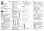
2 Internal Connection
3RZHU
VXSSO\
FLUFXLW
Operating voltage range
Operating time (OFF to ON state) (See Note2)
Response time (ON to OFF state)
Accuracy of OFF-delay time
approx.180 g
approx.180 g
(2) This does not include the bounce time of internal relay in the G9SE.
(3) This is in normal operation. When executing non-regular self-diagnosis for Safety output circuit,
G9SE operating time become 500 ms max..
(4) This is initial value using the voltage-drop method with 1A at 5VDC.
(5) Use for each contact output an 8A fuse that conforms to IEC 60127 as a short-circuit protection device.
This fuse is not included with the G9SE.
(6) Condition: G9SE is mounted to mounting surface with screw and the screw mounting attachment.
In the case of DIN rail mounting, mount DIN rail with G9SE to the place without big vibration.
(Amplitude guideline: Less than 0.15 mm half amplitude (0.3 mm double amplitude))
1 Appearance and Explanation of Each Parts
Type G9SE-201
Rated supply voltage
ex.2) 1.5 second off-delay setting
$ 7 7 7 7 7
G9SE-201
24 VDC
Item
Power
input
余Specifications and performance
6DIHW\
2XWSXWV
LQVWDQWD
QHRXV
6DIHW\
2XWSXWV
2))
GHOD\
Continued on back page
$ 7 7
Safety Input1
;
Suitability for Use
Safety Input2
3 Dimensions
Reset/Feedback
Input
R2.3 17.5
111.6
109
11.4
6.6
4
22.5
Auxiliary output
Two, 4.2 dia.
or M4
4
䣑䣯䣴䣱䣰䢢䣅䣱䣯䣲䣣䣰䣫䣧䣵䢢䣵䣪䣣䣮䣮䢢䣰䣱䣶䢢䣤䣧䢢䣴䣧䣵䣲䣱䣰䣵䣫䣤䣮䣧䢢䣨䣱䣴䢢䣥䣱䣰䣨䣱䣴䣯䣫䣶䣻䢢䣹䣫䣶䣪䢢䣣䣰䣻䢢䣵䣶䣣䣰䣦䣣䣴䣦䣵䢮䢢䣥䣱䣦䣧䣵䢢䣱䣴䢢䣴䣧䣩䣷䣮䣣䣶䣫䣱䣰䣵
䣹䣪䣫䣥䣪䢢䣣䣲䣲䣮䣻䢢䣶䣱䢢䣶䣪䣧䢢䣥䣱䣯䣤䣫䣰䣣䣶䣫䣱䣰䢢䣱䣨䢢䣶䣪䣧䢢䣒䣴䣱䣦䣷䣥䣶䢢䣫䣰䢢䣶䣪䣧䢢䣄䣷䣻䣧䣴䯑䢢䣵䢢䣣䣲䣲䣮䣫䣥䣣䣶䣫䣱䣰䢢䣱䣴䢢䣷䣵䣧䢢䣱䣨䢢䣶䣪䣧䢢䣒䣴䣱䣦䣷䣥䣶䢰䢢䣃䣶
䣄䣷䣻䣧䣴䯑䢢䣵䢢䣴䣧䣳䣷䣧䣵䣶䢮䢢䣑䣯䣴䣱䣰䢢䣹䣫䣮䣮䢢䣲䣴䣱䣸䣫䣦䣧䢢䣣䣲䣲䣮䣫䣥䣣䣤䣮䣧䢢䣶䣪䣫䣴䣦䢢䣲䣣䣴䣶䣻䢢䣥䣧䣴䣶䣫䣨䣫䣥䣣䣶䣫䣱䣰䢢䣦䣱䣥䣷䣯䣧䣰䣶䣵䢢䣫䣦䣧䣰䣶䣫䣨䣻䣫䣰䣩䢢䣴䣣䣶䣫䣰䣩䣵
䣣䣰䣦䢢䣮䣫䣯䣫䣶䣣䣶䣫䣱䣰䣵䢢䣱䣨䢢䣷䣵䣧䢢䣹䣪䣫䣥䣪䢢䣣䣲䣲䣮䣻䢢䣶䣱䢢䣶䣪䣧䢢䣒䣴䣱䣦䣷䣥䣶䢰䢢䣖䣪䣫䣵䢢䣫䣰䣨䣱䣴䣯䣣䣶䣫䣱䣰䢢䣤䣻䢢䣫䣶䣵䣧䣮䣨䢢䣫䣵䢢䣰䣱䣶䢢䣵䣷䣨䣨䣫䣥䣫䣧䣰䣶䢢䣨䣱䣴䢢䣣
䣥䣱䣯䣲䣮䣧䣶䣧䢢䣦䣧䣶䣧䣴䣯䣫䣰䣣䣶䣫䣱䣰䢢䣱䣨䢢䣶䣪䣧䢢䣵䣷䣫䣶䣣䣤䣫䣮䣫䣶䣻䢢䣱䣨䢢䣶䣪䣧䢢䣒䣴䣱䣦䣷䣥䣶䢢䣫䣰䢢䣥䣱䣯䣤䣫䣰䣣䣶䣫䣱䣰䢢䣹䣫䣶䣪䢢䣶䣪䣧䢢䣧䣰䣦䢢䣲䣴䣱䣦䣷䣥䣶䢮䢢䣯䣣䣥䣪䣫䣰䣧䢮
䣵䣻䣵䣶䣧䣯䢮䢢䣱䣴䢢䣱䣶䣪䣧䣴䢢䣣䣲䣲䣮䣫䣥䣣䣶䣫䣱䣰䢢䣱䣴䢢䣷䣵䣧䢰䢢䣄䣷䣻䣧䣴䢢䣵䣪䣣䣮䣮䢢䣤䣧䢢䣵䣱䣮䣧䣮䣻䢢䣴䣧䣵䣲䣱䣰䣵䣫䣤䣮䣧䢢䣨䣱䣴䢢䣦䣧䣶䣧䣴䣯䣫䣰䣫䣰䣩䢢䣣䣲䣲䣴䣱䣲䣴䣫䣣䣶䣧䣰䣧䣵䣵
䣱䣨䢢䣶䣪䣧䢢䣲䣣䣴䣶䣫䣥䣷䣮䣣䣴䢢䣒䣴䣱䣦䣷䣥䣶䢢䣹䣫䣶䣪䢢䣴䣧䣵䣲䣧䣥䣶䢢䣶䣱䢢䣄䣷䣻䣧䣴䯑䢢䣵䢢䣣䣲䣲䣮䣫䣥䣣䣶䣫䣱䣰䢮䢢䣲䣴䣱䣦䣷䣥䣶䢢䣱䣴䢢䣵䣻䣵䣶䣧䣯䢰䢢䣄䣷䣻䣧䣴䢢䣵䣪䣣䣮䣮䢢䣶䣣䣭䣧
䣣䣲䣲䣮䣫䣥䣣䣶䣫䣱䣰䢢䣴䣧䣵䣲䣱䣰䣵䣫䣤䣫䣮䣫䣶䣻䢢䣫䣰䢢䣣䣮䣮䢢䣥䣣䣵䣧䣵䢰
䣐䣇䣘䣇䣔䢢䣗䣕䣇䢢䣖䣊䣇䢢䣒䣔䣑䣆䣗䣅䣖䢢䣈䣑䣔䢢䣃䣐䢢䣃䣒䣒䣎䣋䣅䣃䣖䣋䣑䣐䢢䣋䣐䣘䣑䣎䣘䣋䣐䣉䢢䣕䣇䣔䣋䣑䣗䣕䢢䣔䣋䣕䣍䢢䣖䣑䢢䣎䣋䣈䣇䢢䣑䣔
䣒䣔䣑䣒䣇䣔䣖䣛䢢䣑䣔䢢䣋䣐䢢䣎䣃䣔䣉䣇䢢䣓䣗䣃䣐䣖䣋䣖䣋䣇䣕䢢䣙䣋䣖䣊䣑䣗䣖䢢䣇䣐䣕䣗䣔䣋䣐䣉䢢䣖䣊䣃䣖䢢䣖䣊䣇䢢䣕䣛䣕䣖䣇䣏䢢䣃䣕䢢䣃䢢䣙䣊䣑䣎䣇
䣊䣃䣕䢢䣄䣇䣇䣐䢢䣆䣇䣕䣋䣉䣐䣇䣆䢢䣖䣑䢢䣃䣆䣆䣔䣇䣕䣕䢢䣖䣊䣇䢢䣔䣋䣕䣍䣕䢮䢢䣃䣐䣆䢢䣖䣊䣃䣖䢢䣖䣊䣇䢢䣑䣏䣔䣑䣐䢢䣒䣔䣑䣆䣗䣅䣖䢪䣕䢫䢢䣋䣕
䣒䣔䣑䣒䣇䣔䣎䣛䢢䣔䣃䣖䣇䣆䢢䣃䣐䣆䢢䣋䣐䣕䣖䣃䣎䣎䣇䣆䢢䣈䣑䣔䢢䣖䣊䣇䢢䣋䣐䣖䣇䣐䣆䣇䣆䢢䣗䣕䣇䢢䣙䣋䣖䣊䣋䣐䢢䣖䣊䣇䢢䣑䣘䣇䣔䣃䣎䣎
䣇䣓䣗䣋䣒䣏䣇䣐䣖䢢䣑䣔䢢䣕䣛䣕䣖䣇䣏䢰
OMRON Corporation (Manufacturer)
Safety Outputs
(Instantaneous)
133 ±0.3
EU/EC Declaration of Conformity
edge of preset switch is correctly pointed to the off-delay time value which must be set.
余Ratings
71
4022078-4 C
(*1)Set both of the two Off-delay Time Preset Switches, one each on the front and back, to the same value.
When setting the different value, it is detected as a fault.
(*2)See following illustration for setting position of Off-delay Time Preset Switch. Make sure that the direction of cutting
Safety Outputs (OFF-delay)
余LED Indicators
Marking Color
PWR
Green
IN1
Orange
IN2
Orange
OUT
Orange
OUT1
OUT2 Orange
Name
Power supply
Indicator
Safety Input
#1 indicator
Safety Input
#2 indicator
Safety Output
indicator
OFF-delayed
Safety Output
indicator
Function
Lights up while power is supplied.
Blinks corresponding to the occurring error
Lights up while high signal is input to T12
Blinks when error relating to Safety input #1 occurs.
Lights up while high signal is input to T22
Blinks when error relating to Safety input #2 occurs.
Lights up while Safety outputs (13-14, 23-24, 33-34, 43-44) are in ON-state.
Blinks when an error relating to Safety output occurs.
Lights up while off-delayed Safety outputs (37-38, 47-48) are in ON-state.
Blinks when an error relating to Safety off-delayed solid-state output occurs.
73.5
Thank you for purchasing G9SE Safety Relay Unit.
Please read and understand this manual before using the products.
Keep this manual ready to use whenever needed.
Only qualified person trained in professional electrical technique should handle G9SE.
Please consult your OMRON representative if you have any questions or comments.
(1) Handle with care
Do not drop G9SE to the ground or expose to excessive vibration or mechanical shocks. G9SE may be damaged
and may not function properly.
(2) Adhesion of solvent such as alcohol, thinner, trichloroethane or gasoline on the product should be
avoided. Such solvents make the marking on G9SE illegible and cause deterioration of parts.
(3) Conditions of storage
Do not store in such conditions stated below.
1) In direct sunlight
2) At ambient temperatures out of the range of -10 to 55 ℃
3) At relative humidity out of the range of 25% to 85% or under such temperature change that causes
condensation.
4) At atmospheric pressure out of the range 86 to 106 kPa.
5) In corrosive or combustible gases
6) With vibration or mechanical shocks out of the rated values.
7) Under splashing of water, oil, chemicals
8) In the atmosphere containing dust, saline or metal powder and other conductive dusts.
G9SE may be damaged and may not function properly.
(4) At least 50 mm above top face of G9SE and below bottom face of G9SE should be available to apply rated
current to outputs of G9SE and for enough ventilation.
(5) Mounting multiple units
傍 When mounting multiple units close to each other, the rated current will be 3 A. Do not apply a current
higher than 3 A. If the output current is 3 A or more, make sure that there is a minimum distance of
10mm each between all adjacent G9SE units.
(6) DIN rail mounting
Mount G9SE to DIN rails with attachments (TYPE PFP-M, not incorporated to this product), not to
drop out of rails by vibration etc. especially when the length of DIN railing is short compared to the widths of G9SE.
(7) Wire correctly according to 8 Wiring.
(8) Use cables with length less than 100 m to connect to Safety Inputs, Feed-back/Reset inputs, respectively.
(9) G9SE may malfunction due to electro-magnetic disturbances. Be sure to connect the negative terminal of
DC power supply to ground. When using a DC power supply with light curtains, use DC power supply
which has no interruption by a power failure of 20 ms.
(10)This is a class A product. In residential areas it may cause radio interference, in which case the user may be
required to take adequate measures to reduce interference.
(11) Do NOT mix AC load and DC load to be switched in the following terminals.
傍傍傍- G9SE-201 : between 13-14 terminal and 23-24 terminal
傍傍傍- G9SE-401 : between 13-14 terminal and 23-24 terminal, 33-34 terminal and 43-44 terminal
傍傍傍- G9SE-221-TƑ : between 13-14 terminal and 23-24 terminal, 37-38 terminal and 47-48 terminal
(12) Start entire system after more than 2s have passed since applying supply voltage to G9SE.
(13) Set the time duration of OFF-delay (Type G9SE-221-TƑ)
䣕䣥䣴䣧䣹䢢䣯䣱䣷䣰䣶䣫䣰䣩
1) Set the time duration of OFF-delay to an appropriate value
䣣䣶䣶䣣䣥䣪䣯䣧䣰䣶
that does not cause the loss of safety function of system.
2) Set both of the two Off-delay Time Preset Switches, one each
on the front and back, to the same value. When setting the
different value, it is detected as a fault.
After setting, make sure G9SE operating time is correct.
Insert
(14) To determine safety distance to hazards, take into account the
delay of Safety outputs caused by the following time:
1) Response time
2) Preset off-delay time and accuracy of off-delay time
(15) Before G9SE outputs become in ON-state, non-regular selfdiagnosis for Safety output circuit may be executed.
On this occasion, the operating noise of internal relays occurs.
(16) In the place subjected to strong vibration or shock, mount G9SE
to a mounting surface with screws and the screw mounting attachment.
Otherwise, G9SE may not function properly due to vibration or
mechanical shocks out of the rated values caused by sympathetic
vibration of G9SE and the mounting parts, and so on.
Function
Value
Presets OFF-delay For Type G9SE-221-T05
0(default setting value)/0.1/0.2/0.3/0.4/0.5/0.6/0.7/0.8/1.0/1.5/2.0/2.5/3.0/4.0/5.0(s)(*2)
time (duplicate)
For Type G9SE-221-T30
(*1)
0(default setting value)/1/2/4/5/6/7/8/9/10/12/14/16/20/25/30(s)(*2)
3
USER'S MANUAL
Name
OFF-delayed
time preset
switch
124
English
Precautions for Correct Use
4 Ratings and Specifications
Change the value of the preset switches only when G9SE is disconnected from power supply.
3
Type G9SE-401
余Preset Switches (only applies to Type G9SE-221-TƑ)
5.6
Type G9SE-201
Type G9SE-221-TƑ
(14) Perform daily and 6-month inspections for the G9SE. Otherwise, the system may fail to work properly,
resulting in serious injury. Turn OFF the signal to Safety input and make sure G9SE operates without fault by
checking the state of the LED indicator in inspection.
(15) Conformity to requirements of performance level is determined as an entire system. It is recommended to consult
a certification body regarding assessment of conformity to the required safety level.
(16) OMRON shall not be responsible for conformity with any safety standards regarding to customer's entire
system.
(17) Dispose of the Units according to local ordinances as they apply.
5.6
Original instructions
Type G9SE-201 Type G9SE-401
9.9
Mounting holes
Type G9SE-221-TƑ
[mm]
Shiokoji Horikawa, Shimogyo-ku, Kyoto, 600-8530 JAPAN
Regional Headquarters
OMRON EUROPE B.V.
(Representative and Importer in EU)
Wegalaan 67-69, 2132 JD Hoofddorp
The Netherlands
OMRON SCIENTIFIC TECHNOLOGIES INC.
6550 Dumbarton Circle Fremont
CA 94555 U.S.A
Tel: (1) 510-608-3400/Fax: (1) 510-744-1442
OMRON ASIA PACIFIC PTE. LTD.
No. 438A Alexandra Road # 05-05/08
(Lobby 2), Alexandra Technopark,
Singapore 119967
Tel: (65) 6835-3011/Fax: (65) 6835-2711
OMRON (CHINA) CO., LTD.
Room 2211, Bank of China Tower,
200 Yin Cheng Zhong Road,
PuDong New Area, Shanghai, 200120, China
Tel: (86) 21-5037-2222/Fax: (86) 21-5037-2200
Contact: www.ia.omron.com
Note: Specifications subject to change without notice.
●Wiring
Signal
Name
Power
supply
input
Safety
input 1
of inputs and outputs
Terminal
Name
A1,
A2
T11,
T12
5 Examples of application
Description of operation
Wiring
The input terminals for power supply. Connect the power supply plus to the A1
Connect the power source to the A1 and A2 terminal.
terminals.
Connect the power supply minus to the
A2 terminal.
+24V
To set Safety outputs in ON state, HIGH 1-channel
state signals must be input to both of
Safety input
Safety input 1 and Safety input 2.
Otherwise Safety outputs cannot be in
ON state.
T11 T12 T21 T22
7 Fault Detection
Type G9SE-201
凮2-channel emergency stop switch input / Manual reset凰
Note1 : This example is corresponding to category 4
Feedback loop
Device
S1
S2
:Emergency stop switch
S1
S2
:Reset switch
KM1
:Contactor
KM1,KM2
M
:3-phase motor
KM2
Lock
release
signal
Device
S1
S2
:Safety limit switch
:Guard lock safety
door switch
(Mechanical Lock)
:Reset switch
S3
S4
:Lock release switch
KM1,KM2 :Contactor
M
:3-phase motor
KM1
KM2
S2
S4
Safety sensor
2-channel
Type G9SE-221-T伫
凮Guard lock safety door switch (Mechanical Lock)兟 Safety limit switch inputs
/ Manual reset凰
Note1 : This example is corresponding to category 4
Safety input
Safety
input 2
T21,
OSSD1
$ 7 7 7 7 7
OSSD2
To set Safety outputs in ON state, ON Auto reset
state signal must be input to T33.
Otherwise Safety outputs cannot be in
ON state. (See Note1)
T32
T32
Keep these outputs Open when NOT used.
Off-delayed safety outputs.
(See Note2)
Off-delay time is set by off-delay preset
switch.
When the delay time is set to zero,
these outputs can be used as
instantaneous outputs.
$ 7 7
;
Emitter
A2 T21 T22
Note1 : This example is corresponding to category 4
KM1
PWR
IN1
IN1
IN2
IN2
IN2
OUT
OUT
OUT1
A2
T12
T21
T21
T22
T31
T32
T33
OSSD2
KM1 KM2 KM3 KM4
14
24
37
38
47
44
KM2
Checking points and
measures to take
Blink
1) Check the wiring from safety input devices
to G9SE. Or check the inputs sequence of
safety input devices.
Light
off
Guard can be opened.
Reset switch S3
KM1,KM2 N.C. contact
Use the following to wire to G9SE.
- Solid wire: AWG24 to AWG16 (0.25 to 1.5 mm2)
- Stranded wire: AWG24 to AWG16 (0.25 to 1.5 mm2)
Strip the cover of wire no longer than 8 to 10 mm
When using stranded wire, insulated ferrule should be used. Use below insulated ferrule.
But do not use ferrule terminals if G9SE is used as UL Listing. Insert the strand or solid wire(CU only) directly
into the holes on the terminal block.
- Insulated ferrule: AWG24 to AWG16 (0.25 to 1.5 mm2)
- Crimp height(H): 2.0 mm max.
Width(W): 2.7 mm max.
Conductor length: 8 to 10 mm
When using the twin type ferrule, use equal-sized wires and preferred insulated ferrule.
The twin type ferrule should not be above the adjoining release hole.
伪Recommended insulated ferrule: manufactured by Phoenix contact
Wire size
Type
Cross section(mm2) AWG
0,34
22
Single AI 0,34-8TQ
L
0,5
20
AI 0,5-10WH
AI 0,75-10GY
0,75
18
1,0
AI 1-10RD
18
W
1,5
AI 1.5-10BK
16
−
2 x 0.75
Twin AI TWIN2x0.75-10GY
H
余How to insert solid wire and insulated ferrule
The wire should be pushed into the terminal block straight. No need to use the driver.
After inserting, make sure wire is fastened on to terminal block.
Release hole
Wire
PLC etc.
NC
X1
34
43
24
Lock release signal
LED indicator
Expected causes of
the faults
IN2 OUT OUT2
OUT1
Safety inputs: ON-state
1) Mismatch between Safety input 1
and Safety input 2.
(OFF timing)
Blink Blink
IN1
OFF-delay time
23
33
Guard closed → opened
Guard lock safety
door switch S2
Lock release switch S4
1) Check the disturbance level around
G9SE and its related system.
2) Replace with a new product.
6 Performance level and safety category (EN ISO13849-1)
T32
24
KM1 KM2
Rotation of motor
;
13
23
14
1) Check the supply voltage to G9SE.
$X[LOLDU\
RXWSXW
$ 7 7
T33
14
23
6DIHW\
2XWSXW
,QVWDQW
DQHRXV
T22
X1
14
5HVHW
)HHGEDFN
,QSXW
6DIHW\
,QSXW
T12
T32
13
13
3RZHU
VXSSO\
FLUFXLW
T31
T33
X1
24V
2) Replace with a new product.
8 Wiring
48
Operation command
6DIHW\
,QSXW
T21
T31
24 38
KM1,KM2 N.O. contact
A2
T22
14
X1
KM1
M
1) Check the wiring to T31, T32, and T33
Light
Blink
off
Safety limit switch S1
Motor controller
NC
T11
T12
Auxiliary
output
Timing chart
KM4
$ 7 7 7 7 7
A1
T11
Light
up
Safety
Output
(OFFdelay)
Stop signal
OUT2
A2
Reset/
Feedback
Input
Motor controller
(Operation command)
䣖䣻䣲䣧䢢G9SE-221-TƑ
PWR
2) Replace with a new product.
When indicators other than PWR indicator blink while PWR indicator lights up, check and take needed
measures referring to the following table. After removing the fault, turn both safety inputs to OFF state.
37 47
Safety
Output
(Instant
aneous)
PLC etc.
Device
Safety sensor
KM1∼KM4 :Contactor
M1,M2
:3-phase motor
KM3
OSSD1
●Terminal arrangement and LED indicators
IN1
13 23
Feedback loop
Receiver
640 Ps Max.
PWR
Safety
Input1
Safety
Input2
KM1,KM2 NO contact
KM2
T11
Power
supply
circuit
24V
Type G9SE-401
凮2-channel safety sensor / Auto reset凰
Safety
sensor
1) Supply voltage outside the
rated value.
1) By excessive electro-magnetic
disturbance.
The all indicators Light off 2) Failures of the parts of internal
circuits
KM1,KM2 NC contact
In many case, Safety Sensor outputs include the off-shot pulse for its self test.
The following condition of test pulse is applicable as safety inputs for G9SE.
- Off-shot pulse width of the sensor, during the ON-state : 640 μs
A1
The all indicators Blink
Stop signal
PWR
Reset switch S2
1) Check the wiring to T21 and T22.
Blink
Emergency stop switch S1
KM2
2) Replace with a new product.
1) Mismatch of the two Off-delay 1) Check both of the two Off-delay Time
Time Preset Switches.
Preset Switches.
Timing chart
KM1
1) Check the wiring to T11 and T12.
KM2
KM1 KM2
1) Failures involving the wiring of
Safety input 1
2) Failures of the parts of the circuits
of Safety input 1.
1) Failures involving the wiring of
Safety input 2
2) Failures of the parts of the circuits
of Safety input 2.
1) Failures involving the wiring of
Feedback/Reset input.
2) Failures of the parts of the circuits
of Feedback/Reset input.
Blink
KM1
A1 T11 T12 T31 T32 T33
M
●Connecting Safety Sensors and G9SE
䣖䣻䣲䣧䢢G9SE-401
Blink
S3
S1
Checking points and
measures to take
1) Failures of the parts or relays of the 1) Replace with a new product.
circuits of Safety Output.
Feedback loop
Guard
Expected causes of
the faults
Light Light
off
off
OPEN
Keep these outputs Open when NOT used.
(1) Construct the safety system taking into account that in the Auto reset mode Safety outputs turn ON
automatically when Safety inputs 1 and 2 turn ON.
(2) When the inputs of G9SE-221-TƑ are restored during off-delay time, G9SE-221-TƑ will operate
as below. Depending on the reset mode.
- Auto reset mode: Outputs turn off after off-delay time, then immediately turns on.
- Manual reset mode: Outputs turn off after off-delay time, then turn on when reset input is given.
A1
Safety inputs: ON-state
T33
Off37-38,
delayed 47-48
Safety
output
䣖䣻䣲䣧䢢G9SE-201
Blink
Blink
$X[LOLDU\
RXWSXW
PLC etc.
T31
LED indicator
IN2 OUT OUT2
OUT1
IN1
Blink
KM +24V
Turns ON/OFF according to the state of Keep these outputs Open when NOT used.
safety inputs, Feedback/Reset inputs.
During off-delay state, safety outputs
are not able to turn ON.
Outputs a signal of the same logic as
Safety outputs
6DIHW\
2XWSXW
,QVWDQW
DQHRXV
T33
Feedback loop
13-14,
23-24,
33-34,
43-44,
Auxiliary X1
output
5HVHW
)HHGEDFN
,QSXW
6DIHW\
,QSXW
KM
+24V
Reset
Switch
6DIHW\
,QSXW
3RZHU
VXSSO\
FLUFXLW
24V
Feedback loop
T31
To set Safety outputs in ON state, the Manual
signal input to T32 must change from reset
OFF state to ON state, and then to OFF
state. Otherwise Safety outputs cannot
be in ON state.
Safety
output
PWR
Light Light
up
up
Safety inputs: OFF-state
T11 T12 T21 T22
T33
When PWR indicator blinks, check and take needed measures referring to the following table. And then
apply supply voltage to G9SE.
T11 T12 T21 T22
T22
Reset/
T31,
Feedback T32,
input
When G9SE detects a fault, LED indicators blink to show the information of the fault.
48
Timing chart
KM1
KM3
KM2
KM4
Safety sesor outputs
KM1∼KM4 NC contact
KM1∼KM4 NO contact
M1
M2
In the conditions shown in '5.Examples of Application' , G9SE can be used for the corresponding safety
categories up to 4 and performance level(PL) up to e per ISO13849-1.
This does NOT mean that G9SE can always be used for the required category under all the similar conditions
and situations.
Conformity to the categories must be assessed as a whole system.
When using G9SE for the safety categories, make sure the conformity of the whole system.
1) Input the signals to both of the Safety inputs (T12 and T22)
2) Input a signal to the Safety inputs (T11-T12 and T21-T22) through switches with Direct Opening
Mechanism. When using limit switches, at least one of them must have Direct Opening Mechanism.
And wiring must be done in a way that a short circuit between the wires of Safety input can be
prevented.
3) When connecting a Safety sensor with G9SE, use a TYPE 4 safety sensor.
4) Be sure to connect the negative terminal of DC power supply to ground.
5) Use two Safety outputs (e.g. 13-14 and 23-24) to construct the system.
6) In order to ensure sufficient failure detection, it is mandatory to use G9SE only together with
contactors or relays with forcibly guided contacts.
7) Input the signal through NC contacts of the contactors to Feedback/Reset input (T31-T32 for manual
reset or T31-T33 for auto reset). (Refer to '5.Examples of Application'.)
余How to release wire
Use the following minus drive to release wire from terminal block.
And When releasing wire, the power source should be disconnected first.
1. Push the driver lightly into the taper of release hole.
2. Pull out the wire while the driver is pushed into release hole.
3. Pull out the driver.
Side
(8到12°)
Front
ø2.5mm max.
Driver
(0.4mm)
2.5mm max.
Recommended driver:
Type SZF0-0.4mmx2.5mm
manufactured by Phoenix contact
Type XW4Z-00B manufactured by Omron
余Precautions for Correct wiring
Terminal block may be damaged.
1. Not push the driver into the release hole straight.
2. Not push the driver into the release hole by force of 30N and over.
3. Not tip or twist the driver pushed into release hole.