1
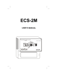
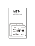
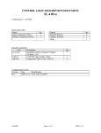
CIP-1/6
User’s Manual
Varifan
50
60
40
AUTO
30
80
20
MOTOR ON
90
10
100
0
CIP-
MAN
70
AUTO
LOCK
AUTO
CIP-1/6
Although the manufacturer has made every effort to
ensure the accuracy of the information contained
herein, this document is subject to change without
notice due to ongoing product development.
WARNING AND PRECAUTIONS
Equipment, probe failure, blown fuses and/or tripped
breakers may prove harmful to the contents of the
building. Therefore it is strongly recommended to
install backup devices and alarm or warning devices.
Spare equipment should also be available at the
user’s site. Equipment manufactured by the
manufacturer is protected against normal line surges.
High surges caused by thunder storms or power
supply equipment may damage this equipment. For
added security against line voltage surges, it is
recommended that surge and noise suppression
devices be installed at the electrical distribution
panel. Use of shielded cable for probes is
recommended for protection against lightning. These
devices are available from most electrical supply
distributors.
RECOMMENDATIONS
The manufacturer recommends that all installation
procedures described herein be performed by a
qualified electrician or installation technician.
Furthermore the manufacturer recommends to test all
the functions and equipment connected to the
CIP-1/6, including the alarm system and backup
devices, after installation, after changes to the
installation and every month after that.
Fuse verification and replacement, as well as the
proper setting of module values shall be the
responsibility of the owner of this equipment.
Page 2
TABLE OF CONTENTS
TABLE OF CONTENTS
INTRODUCTION
1.
1.1
General ...................................................................................4
Description .............................................................................4
INSTALLATION
2.1
2.2
2.3
2.3.1
2.3.2
2.3.3
2.4
2.4.1
2.4.2
2.5
2.6
Unpacking ..............................................................................5
Mounting ................................................................................6
Connection Procedure.............................................................7
Cabling ...................................................................................7
Connections to the Actuator Motor.........................................7
Connection to a master control ...............................................8
Switch Settings .......................................................................8
Line Voltage Selector Switch .................................................8
Software Settings Switch ........................................................8
Powering Up ..........................................................................10
Calibration .............................................................................11
USER GUIDE
User Guide...........................................................................................15
APPENDIX
Troubleshooting...................................................................................17
Specifications ......................................................................................18
WARRANTY
Limited Warranty ................................................................................19
Page 3
CIP-1/6
1. GENERAL
This document provides you with the necessary
information to install and operate the CIP-1/6.
The document is presented as follows:
• Introduction
• Installation
• User’s Guide
• Appendix
1.1 DESCRIPTION
The CIP-1/6 is designed to operate an actuator
without the use of a feedback potentiometer or
0-10 volts analog signal.
The CIP-1/6 provides you with automated actuator
via the use master control or by manual switch on
the CIP-1/6 front panel.
At all time, the CIP-1/6 keeps you informed of it’s
status via LED indications.
Page 4
INSTALLATION
2. INSTALLATION
Chapter 2 describes the installation procedure for
the CIP-1/6.
The manufacturer recommends that the
following installation instructions be observed
very carefully, and that all the work be
performed by a certified electrician. Failure to
comply may void the warranty!
2.1 UNPACKING
Unpack the CIP-1/6 from its box and inspect
contents for damage. Should the contents appear to
be damaged, contact your local distributor for
return material procedures.
The package should contain the following standard
items:
• 1 CIP-1/6 module
• 2 cable fasteners or a fuse
• 1 user’s manual
Page 5
CIP-1/6
2.2 INSTALLATION
Install the CIP-1/6 module on the wall using the
mounting holes located on the sides of the module.
Once the CIP-1/6 is in place, use a screwdriver to
remove the four screws holding the faceplate to the
housing.
It is recommended to install the unit in a
hallway to limit the module’s exposure to
noxious gases.
Make sure the unit is properly installed, that
is, side up with the cable entry holes facing
down.
The CIP-1/6 will operate in a temperature
range of 32°F to 120°F (0°C to 50°C).
The enclosure is watertight, but not splashproof or immersion proof. DO NOT WATER
the module. Cover it carefully with plastic
when cleaning the room. Do not drill
additional holes in the enclosure.
It is prohibited to use overhead cables outside
the building.
Page 6
INSTALLATION
2.3 CONNECTION PROCEDURE
For the following procedures, refer to figures 1 to
3.
Do not apply power to the module until all
connections have been completed. The current
draw of the load should be in the range of
75mA to 6A. Set the voltage switch inside the
CIP-1/6 to correct value before attempting to
operate.
2.3.1 Cabling
Use a screwdriver to remove cable knock-outs for
the installation of cabling to the module.
2.3.2 Connections to the Actuator Motor
Refer to figure 1 and the following procedure for
standard actuator, to figure 2 for actuator using
Hired Hand switch box (PVR-2) or to figure 3 for a
3 phase actuator.
3 WIRES ACTUATOR
•
•
•
•
•
Connect L1 of the power source to terminal 1
and terminal 3.
Connect L2/N of the power source to the
common of the actuator motor and to the
terminal 2.
Connect terminal 4 with terminal 5.
Connect lead of the actuator motor associated
with opening to terminal 7.
Connect the lead of the actuator motor
associated with closing to terminal 6.
Page 7
CIP-1/6
2.3.3 Connection to a master control
Install a 18 AWG cable pair between the CIP-1/6
and the master control. The cable can extend to a
maximum lenght of 500 feet (150M).
Connect one end of the cable to the (+) and (-)
terminals of the CIP-1/6 low voltage terminal
block. Refer to the bottom left corner of the main
board in figures 1 or 2.
2.4 SWITCH SETTINGS
2.4.1 Line voltage selector switch
This switch is located on the surface of the main
(bottom) board and adapts the module for 115VAC
or 230 VAC line voltage. Refer to Figures 1 and 2.
2.4.2 Software setting switches
The CIP-1/6 is configured to function in different
conditions via 4 switches.
These switches are located behind the faceplate and
adjusts the following options:
Page 8
INSTALLATION
OFF ON
1
2
3
4
OFF
ON
Auto-c. Off
Auto-c. / 50
Air inlet
Opening calibration
Auto-c. On
Auto-c. / 250
Valve
Closing calibration
Switch 1: Enables/ disables Auto-Calibration.
Switch 2: Activate Auto-calibration after 50 or 250
changes of direction.
Switch 3: Allows opposite logic. Thus, the CIP-1/6
can either be used on an actuator or on a motorized
valve of a hot water heating system. actuator more it
opens, more the room cools down. Valve (heater)
more it opens, more the room heats up.
Switch 4 : Auto-calibration in opening or closing
mode (after 50 or 250 changes of direction). When
tunnel ventilation is active and switch 4 is in closing
mode, static pressure might build up and immobilize
the actuator. However, in opening mode (switch 4
OFF), if actuator remains open too long in cold
weather, animals may get cold.
The Auto-calibration allows the CIP-1/6 to reposition
the actuator precisely. During that process, the
actuator will open or close completely (depending on
switch 4) and will return to the commanded position.
CAUTION
If opening time is different from closing time,
Auto-calibration must be activated. The
difference between opening and closing time
must not exceed 25%. If it does, it is better to use
the Smart Ventilation Inlet Module (SVIM).
Page 9
CIP-1/6
2.5 POWERING UP
Before powering up the CIP-1/6, attach the
faceplate to the casing of the module using the four
screws previously removed.
Make sure the line voltage selector switch is set
properly.
CAUTION
Make sure that module is connected on the
same phase as the control. Otherwise the
positioning will not be as expected.
Page 10
INSTALLATION
2.6 CALIBRATION
In order to work properly, the CIP-1/6 has to be
manually calibrated the first time it is started. The
initial calibration is done by following those 3
steps:
Step 1: Be sure the CIP-1/6 is in manual mode.
Step 2: Set the position at 0% and wait for the
motor to stop. If the position is already at 0%, set it
at 10% and set it back at 0% so that it records its
own 0%.
Step 3: Set the position at 100% and wait for the
motor to stop.
This calibration allows the CIP-1/6 to register the
actuator’s maximum and minimum positions.
If the actuator needs more than 16 minutes (50Hz)
or 19 minutes (60Hz) to open, the intermediate
positions (from 10% to 90%) won’t be accurate.
Only the limits positions (0% and 100%) will be
exact. Apart from the offset in the middle
positions, the operation of the CIP-1/6 will be
normal.
To test the unit independently of the master control, set the toggle switch to MAN (manual). Use
the position knob to open or close the actuator. If
the actuator does not operate, refer to the
Troubleshooting section in the appendix of this
document.
When you have completed verifying and
calibrating the actuator motor operation, set the
toggle switch to AUTO.
Page 11
CIP-1/6
Figure 1 Connection of a 3 wires actuator motor.
WARNING!
SET LINE VOLTAGE SWITCH
TO CORRECT VALUE
BEFORE ATTEMPTING TO
OPERATE.
1044 A
Page 12
INSTALLATION
Figure 2 Connection of actuator motor with HIRED HAND
(PVR-2) switch box.
CIP-1
WARNING!
6A
SLO-BLO
FUSE
SET LINE VOLTAGE SWITCH
TO CORRECT VALUE
BEFORE ATTEMPTING TO
OPERATE
+ -
115V
LOW VOLTAGE
INPUT LINKED
TO MASTER
CONTROL.
LINE VOLTAGE
SELECTOR
1
2
LINE
VOLTAGE
3
4
CURRENT
DETECTOR
5
6
7
COM CLOSE OPEN
8
N/C
1044 A
N / WHITE
LINE
115 VAC
L1 / BLACK
1
WHITE
YELLOW
GREEN
FROM
ACTUATOR
BLACK
ORANGE
2
BLUE
RED
BROWN
1
2
3
4
5
6
7
8
9
10 11
12
HIRED HAND SWITCH BOX
1
Power cut and protection devices in case of overload.
2
Do not connect this wire if your are using a HIRED HAND
with an external switch.
Page 13
CIP-1/6
Figure 3 Connection of actuator motor with 3 phases
CIP-1
L1
L2
L3
POWER
RELAY
CLOSED
POWER
RELAY
OPEN
N.C.
N.O.
N.O.
N.O.
N.C.
N.O.
N
N.C.
MOTOR
Page 14
LIMIT SWITCH
CLOSED
N.C.
LIMIT SWITCH
OPEN
N.O.
N.O.
USER GUIDE
50
60
40
AUTO
MOTOR ON
MAN
70
30
80
20
90
10
100
0
AUTO
LOCK
AUTO
The CIP-1/6 faceplate (shown above) features one
toggle switch, one position knob and two status
LEDs. The toggle switch is used to select whether
the actuator motor operates in auto mode or under
manual.
The position knob is used to select the desired
position of the actuator ranging from 0% to 100%.
The AUTO LOCK mode indicates to the control
that if in automatic mode and that the master
control stops sending the desired position, the
curtain stays at the last requested position.
A status LED called MOTOR ON indicates if the
actuator is moving (LED on) or not (LED off). The
other status LED called AUTO indicates whether
the control is in automatic (LED on) or in manual
mode (LED off). If the CIP-1/6 is in automatic
mode and loses its communication link with the
master control unit, it switches to manual mode and
the actuator goes to the position indicated by the
knob or, if in AUTO LOCK mode, the actuator
stays at the last requested position.
Page 15
CIP-1/6
The toggle switch allows the actuator motor to be
set in one of two modes as follows:
•
•
Page 16
MAN: To manually select the position of the
actuator with the use of the knob, switch to the
manual mode. The position can then be set
from 0% to 100%. The AUTO LOCK cannot
be used in manual mode.
AUTO: To allow the actuator motor to operate
under the master control, set the toggle switch
to AUTO.
APPENDIX
TROUBLESHOOTING
Set the toggle switch on the
CIP-1/6 to MAN (manual),
and use the position knob
to open or close the
actuator.
Is
the actuator motor
operating correctly?
NO
YES
Verify
the
p o w e r
connections to
the
CIP-1/6,
fuses,
and
actuator motor.
Calibrate the CIP-1/6 as
shown in section 2.6 then
set the toggle switch to
AUTO. Adjust the master
control to allow the air
inlet to operate.
YES
The unit is
OK.
Is the actuator motor
operating correctly?
NO
Verify the status of the
AUTO LED on the
CIP-1/6.
Is the AUTO LED of the
CIP-1/6 ON?
YES
NO
Verify the low
voltage cable
between
the
master control
and CIP-1/6.
Contact your dealer for
service.
NOTE: When calling for service take note of the LED
status of the master control and the CIP-1/6.
Page 17
CIP-1/6
SPECIFICATIONS
Description
Value
OPEN /
CLOSED
(solid state
relays)
- 6 AMP; 115/230V
- 50/60 Hz
- 1/2 HP @ 230V
- 1/4 HP @ 115V
- Fuse 6 A slo-blo
Operating range of the CIP-1/6 current
detector
•
•
Page 18
At the end of its course, the actuator
current must be less than 25 mA.
While moving, the actuator current
must be more than 75 mA.
WARRANTY
Limited Warranty
The manufacturered equipment and supplied
components have gone through rigorous inspection to
assure optimal quality of product and reliability.
Individual controls are factory tested under load,
however the possibility of equipment failure and/or
malfunction may still exist.
For service, contact your local retailer or supplier.
The warranty period shall be for two years from
manufacturing date. Proof of purchase is required for
warranty validation.
In all cases, the warranty shall apply only to defects
in workmanship and specifically exclude any damage
caused by over-voltage, short circuit, misuse, acts of
vandalism, lightning, fortuitous events, acts of God,
flood, fire, hail or any other natural disaster. Any
unauthorized work, modification or repair on this
product automatically voids the warranty and
disclaims the manufacturer from all responsibility.
The manufacturer assumes only those obligations set
forth herein, excluding all other warranties or
obligations. This warranty stipulates that in all cases
the manufacturer shall be liable only for the supply of
replacement parts or goods and shall not be liable for
any personal injury, damages, loss of profits,
interrupted operations, fines for infringement of the
law or damages to the production of the
PURCHASER and the PURCHASER shall take up
the defense and hold the manufacturer faultless
regarding any legal or extra legal proceedings, notice,
or claim by the customer or by a third party, and
regarding any legal and extra legal expenses and fees
brought forward on by such damages.
Page 19
MAVCIP-1/6
VER:4.3
rev 09/02/2006
chip. v. 107