1
US008428981B2
(12) United States Patent
(10) Patent N0.:
Li et a1.
US 8,428,981 B2
(45) Date of Patent:
<52
Apr. 23, 2013
22222222222 22: 222222
AUTOMATICALLY MAINTAINING THE
CONSISTENCY OF AN INFORMATION
SYSTEM
.
.
2008/0104092 A1*
~~~~~~~~~~~~~~~~~~ "722222
5/2008 cifmilnniri'sm... .............. .11. 707/101
OTHER PUBLICATIONS
_
Webpage entitled “IBM ILOG”, accessed from the Internet at <http://
(75) Inventors: Pelsong L1, Shangha1 (CN); Peng Gao,
Shanghai (CN); Ligang Cheng:
Shanghai (CN); Mu Yll, Shanghai (CN)
www‘ilog‘comz NOV‘ 29, 2012‘
Webpage entitled “DroolsilBoss Community”, accessed from the
Internet at <http://WWW.jb0ss.0rt/dr00ls/>, Nov. 29, 2012.
(73) Assignee: SAP AG, Walldorf (DE)
* cited by examiner
(*)
Subject to any disclaimer, the term of this
patent is extended or adjusted under 35
Primary Examine?’ * Nga B- Nguyen
(74) Attorney, Agent, or Firm * MintZ Levin Cohn Ferris
U.S.C. 154(b) by 1541 days.
Glovsky and Popeo, RC.
Notice:
(21) App1.No.: 11/637,523
.
(22) Flled:
(57)
Int- ClG06Q 30/00
ERP s stem maintains a
represents a business function that may or may not be needed
depending on a customer’s business requirement. A scoping
process is a process Which determines What business ele
ments are required according to the customer’s business
Jun. 12, 2008
requirement and the relationships exist among some of the
business elements. The ERP system provides an automatic
business con?guration subsystem. The automatic business
(2006-01)
(52) US ClUSPC .... .. 705/7; 705/34; 705/35; 705/36; 707/101;
707/102; 707/103
(58)
rise Resource Plannin
pluralityrgf business elements. E5011 of the business elements
Prior Publication Data
US 2008/0140475 A1
(51)
An Ente
Dec‘ 11’ 2006
(65)
ABSTRACT
Field of Classi?cation Search .............. .. 705/7, 34,
705/35, 36; 707/101, 102, 103
See application ?le for complete search history.
con?guration subsystem maintains a set ofrules. Each ofthe
rules representing a relationship betWeen tWo business ele
ments maintained at the ERP system. The automatic business
con?guration subsystem automatically determines Which
business elements are required and need to be implemented
based on the set of rules. The automatic business con?gura
(56)
References Cited
tion subsystem may also automatically determine Whether
statuses of the business elements are consistent With each
U.S. PATENT DOCUMENTS
5,878,431 A *
3/1999
other in View of the rules.
Potterveld et a1. ...... .. 707/103 R
2003/0216938 A1* 11/2003 Shour
Client 12
............................. ..
705/2
15 Claims, 13 Drawing Sheets
Interface Module
Client 12
Client-side
ERP
1 06
Client-side
application
Automatic Business Con?guration Subsystem (A565) 105
application
J5
13
Workspace Module Z115
Module 211
Enterprise Resource Planning (ERP) System J_1_
Interface Module 115
Automatic Business Con?guration Subsystem (ABCS)
105
Persistence
m
Elements
1L1.
Package
ILQZ
Topic
- Business
Option
1124
Consistency Maintenance }
Framework (CMF) m
Rebuilder Module 2_QZ
US. Patent
Apr. 23, 2013
Sheet 1 0f 13
Client Q
US 8,428,981 B2
Client 12
Client-side
ERP
Client-side
ERP
application
application
1_4
14
Enterprise Resource Planning (ERP) System ?
Interface Module 10
i
i
Automatic Business Con?guration Subsystem (ABCS)
1
V
;
.
Elements
Business
Package
M
Business
5
Business
Topic
Business
.10_3
Option
M
Fig. 1
101
—
'
US. Patent
Apr. 23, 2013
Sheet 2 0f 13
US 8,428,981 B2
interface Module
‘
106
Automatic Business Con?guration Subsystem (ABCS) 1_Q_€_>
Workspace Module E
A
l
Business Con?guration Logic
Module @
v
Deduction Framework 2 3
v
Rule Base Module 2 2
7
Rule Semantics Module 2m
Persistence
M
7
Consistency Maintenance
Framework (CMF) m
FIG. 2
Rebuilder Module M
US. Patent
Apr. 23, 2013
Sheet 4 0f 13
US 8,428,981 B2
309
f 305
303
Business Iopl Repoc?vg
Constraint
' hide details in arailel
306
,
A. Rgpmjngjs SELBSTQQ
i”
;
J El
307
[1
I
.'::.
-»
'
_
‘ _
'
v
‘
-;
-'
.
V
‘$1
_7
‘_,_
A“
i
J
IF EPA Sales Order/Vhmgernenl IS SELECTcO AND HP»? Procurement Management 15 SELECTED
0/? F SPA A-zcoanM/hnagemont IS 55150.?50
i_'_,v Repolting ISDESELECTEDQ
/ 308
l
i [3
IF SPA Sales Order Minagement 1'15 NOISE‘ FOE-‘E1 OR 5P4 Procurememlvhnagement ISNDTSELEC TEL‘
] '7 AND IF EPA Account Management rs NOTSELEC TED
309
I
i B A ND IF EPA Vender mom 15 55150750
304
31 1
31 2
- .
/
EPA Sales Order Managemer?
/ E]
AND
F'§§_A_Pmr:ummnr? Mnnsgnmem
)3
AND
1‘
WI.
31 1
1
LJ OR
L
I
AND
if? ON
[1
AND
'
.
It?,
A
.
;,,;'IS SELECIED
..
-
EQISSFLEQIFD
{a
igls>sascrang<é
-1
h
RPA Amnum Management
r
RLYEJSQECIEDV
j
@
f
11:11
{. .kascutcmo‘,
;
E}
Q ;s SELEQIEDLQMQ
FIG. 3b
/— 313
/
"'W
‘
0H‘
3
US. Patent
Apr. 23, 2013
Sheet 5 0f 13
US 8,428,981 B2
Business Element
Business Element
w
4_0_1.
GetSinkRules %
RuleSet @
RuleSet 59g
SinkRules
SinkRules
593
m
SourceRuIes
SourceRules
m
m
GetSourceRules
%
FIG. 4
US. Patent
Apr. 23 , 2013
Sheet 6 0f 13
US 8,428,981 B2
CentralRuleBase
&
RUIGBGSe/SOK
/
wse Q
05
55
SessionRule
SessionRule
Base @
Base @
Session 504
Session 504
FIG. 5
US. Patent
Apr. 23, 2013
Sheet 7 0f 13
Deduction Framework 2 3
Default Value Handler Q91
Relationship Handler @Qg
Status Determination Module
m
Explanation Determination
Module w
FIG. 6
US 8,428,981 B2
US. Patent
Apr. 23, 2013
Sheet 8 0f 13
Consistency Maintenance Framework (CMF) m
Preprocessing Module m
Solution Generator m
FIG. 7
US 8,428,981 B2
US. Patent
Apr. 23, 2013
Sheet 9 0f 13
US 8,428,981 B2
801
Create and initialize a scoping
process
7
’
Receive a request from a client
side ERP application and
determine what the request is
v
/ 803
Process the scoping request
v
/ 804
Process the explanation request
FIG. 8
US. Patent
Apr. 23, 2013
Sheet 10 0f 13
US 8,428,981 B2
901
Create a workspace object and
pass control to the workspace
object
902
Create a business configuration
logic object and pass control to it
K
%
903
Read initial facts from the
persistence
904
Determine status of other business
FIG 98
elements based on the initial facts
End
US. Patent
Apr. 23, 2013
Sheet 12 0f 13
Receiving a set of nodes and a set
US 8,428,981 B2
J 1001
ofnogoods
V
’ Resolving contradictions within the
set of nodes
J
1002
J
1003
V
Creating a set, NG, including all
nogoods that are subsets of the set
of nodes
1006‘1
1004
¢ W»
Return the current node set as
solution
No
i
1005
For each node, counting the K
value and the N value of the node
V
1007
Sorting the nodes in descending
order according to K value, if two
nodes tie with K value, sorting them
in ascending order according to N
value
17
Change the top node to its opposite
node
1008
Fig. 10
US. Patent
Apr. 23, 2013
9E52360
2N0o:62
Sheet 13 0f 13
US 8,428,981 B2
US 8,428,981 B2
1
2
METHOD AND SYSTEM FOR
AUTOMATICALLY MAINTAINING THE
CONSISTENCY OF AN INFORMATION
SYSTEM
of the accompanying draWings, in Which like references indi
cate similar elements and in Which:
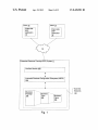
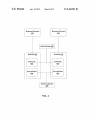
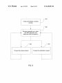
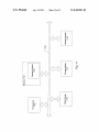
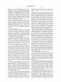
FIG. 1 illustrates a netWork environment in Which an
embodiment of the invention may be implemented;
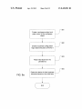
FIG. 2 illustrates an example of an architecture of anAuto
COPYRIGHT NOTICES
matic Business Con?guration Subsystem (ABCS);
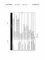
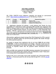
FIG. 3a illustrates an example of a set of rule grammars
A portion of the disclosure of this patent document con
according to one embodiment;
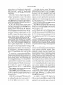
FIG. 3b illustrates an example of a Graphic User Interface
tains material Which is subject to copyright protection. The
copyright oWner has no objection to the facsimile reproduc
tion by anyone of the patent document or the patent disclo
(GUI) through Which a user may input a rule into an ERP
?le or records, but otherWise reserves all copyright rights
Whatsoever.
system according to one embodiment;
FIG. 4 is a block diagram illustrating an instance of the rule
base module in memory according to one embodiment;
FIELD OF THE INVENTION
consumed by multiple instances of the rule base module for
sure, as it appears in the Patent and Trademark Of?ce patent
FIG. 5 illustrates a mechanism to reduce a memory siZe
supporting multiple users/developers according to one
At least one embodiment of the present invention pertains
to Information systems, and more particularly, to automati
embodiment;
cally con?guring an information system.
tion frameWork according to one embodiment;
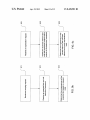
FIG. 6 illustrates an example of an architecture of a deduc
20
one embodiment;
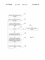
FIG. 8 is a How diagram illustrating an example of a scop
As Enterprise Resource Planning (ERP) methodology has
become more popular, software applications have emerged to
help business managers implement ERP in business activities
such as inventory control, order tracking, customer service,
25
?nance and human resources, etc.
Business Con?guration of an ERP system requires com
prehensive knoWledge of the ERP system and its capabilities.
Speci?cally, dependencies among different functions of the
30
generator according to one embodiment; and
FIG. 11 is a block diagram shoWing an example of a pro
cessing system.
35
DETAILED DESCRIPTION
A method and system for automatically con?guring an
Enterprise Resource Planning (ERP) system are described.
tions means that the customer cannot run “Sales Order Man
agement” function.
40
In conventional ERP systems, a scoping process (i.e., the
task of determining What business functions of an ERP sys
tem are required according to a customer’s business require
References in this speci?cation to “an embodiment”, “one
embodiment”, or the like, mean that the particular feature,
structure or characteristic being described is included in at
least one embodiment of the present invention. Occurrences
of such phrases in this speci?cation do not necessarily all
ment) is handled manually by experienced, highly quali?ed
consultants by analyZing the business requirement, determin
ing process according to one embodiment;
FIG. 9a is a How diagram illustrating a scoping process
according to an alternative embodiment;
FIG. 9b is a How diagram illustrating a scoping process
according to another embodiment;
FIG. 90 is a How diagram illustrating a scoping process
according to another embodiment;
FIG. 10 is a How diagram illustrating a process of a solution
ERP system and their con?gurations are required in order to
determine What functions need to be implemented and What
system behaviour must be con?gured. For example, if a cus
tomer chooses to implement the “Sales Order Management”
function, the customer must also implement the “Basic Sales
Order” and “Pricing” functions if the “Sales Order Manage
ment” function depends on the “Basic Sales Order” function
and the “Pricing” function. Failure to implement these func
FIG. 7 illustrates an example of an architecture of the
Consistency Maintenance Framework (DMF) according to
BACKGROUND
45
refer to the same embodiment.
ing a business solution, and implementing the business solu
tion by con?guring the ERP system. The more complicated
1. Enterprise Resource Planning System
the business system is, the more dif?cult to implement the
business solution in a purely manual fashion.
embodiment of the invention may be implemented. As
FIG. 1 illustrates a netWork environment in Which an
shoWn, an Enterprise Resource Planning (ERP) system 11 is
50
SUMMARY OF THE INVENTION
The present invention includes a method for automatically
Work (MAN) or the Internet, and may implement the Internet
con?guring an Enterprise Resource Planning (ERP) system.
The method includes maintaining a plurality of business ele
ments at an Enterprise Resource Planning (ERP) system. The
55
Protocol (IP). Each of the clients 12 runs a client-side ERP
application 14. Such an application may be, for example, a
Web-based application that alloWs a user to login to the ERP
system 11 and to Work on a business con?guration project. A
user may communicate With the ERP system 11 by submit
method further includes automatically determining Whether
statuses of the plurality of business elements are consistent
With each other.
Other aspects of the invention Will be apparent from the
communicatively coupled to a number of clients 12 via an
interconnect 13. The interconnect 13 may be essentially any
type of computer netWork, such as a local area netWork
(LAN), a Wide area netWork (WAN), metropolitan area net
accompanying ?gures and from the detailed description
ting commands and receiving results or instructions through
an interface provided by the client-side ERP application 14.
Which folloWs.
In one embodiment, such an interface is a Graphic User
60
Interface (GUI).
BRIEF DESCRIPTION OF THE DRAWINGS
65
One or more embodiments of the present invention are
illustrated by Way of example and not limitation in the ?gures
The ERP system 11 provides a set of business elements
101. Each business element 101 may be a business package
102, a business topic 103, or a business option 104.A business
package 102 may include a set of business topics 103. A
US 8,428,981 B2
3
4
business topic 103 may include a set of business options 104.
For example, an ERP system may provide “Sales Order Man
vides syntax and semantics checks to rules. In one embodi
ment, a user may input rules into the ERP system 11 via the
agement” business package. The “Sales Order Management”
client-side ERP application 14. The rule semantics module
201 parses the rules, transforms the rules into a uni?ed for
mat, and stores the rules into the persistence 206. When called
business package may include business topics such as “Sales
Order Quotation”, “Pricing”, and “Product Con?guration”,
etc. The business topic “Pricing” may include business
options such as “Standard Pricing”, “Seasonal Goods”, etc.
by the rule base module 202 (introduced beloW), the rule
semantics module 201 retrieves these rules from the persis
tence 206 and transforms them into in-core rule objects. Here,
As a result of a business requirement, the function of a
business element may depend on the function of another
business element. In that case, a dependency relationship
exists betWeen the tWo business elements. In knoWn prior art
ERP systems, a user needs to manually determine What busi
ness elements need to be selected and implemented based on
the term “in-core” means in a main memory of a processing
system. The rule semantics module 201 also does redundant
and collision checks for the rules stored in the persistence
206. Redundant checks prevent redundant rules in the persis
tence. Collision checks detect con?icting rules and recursive
rules.
business requirements and dependency relations among these
business elements. The present invention includes an ERP
system Which may automatically determine What business
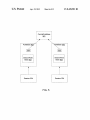
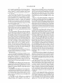
The ABCS 105 further includes a rule base module 202.
elements need to be selected and implemented based on the
After rules are encapsulated as in-core objects by the rule
semantics module 201, the rule base module 202 organiZes
these objects so that they may be easily accessed or searched
business requirement and dependency relations among these
business elements.
In one embodiment, the ERP system 11 may include an
20
The ABCS 105 models the dependency relations as rules. A
rule dictates Whether particular business elements require or
exclude other business elements. Here, the status of a busi
ness element includes tWo aspects. The ?rst aspect is the
business element’s selection status. The value of a selection
status may be “selected” or “deselected”. The second aspect
is the business element’s changeability status. The value of a
25
30
mination and/ or changeability determination functions in
response to receiving an asserted fact. An asserted fact refers
element’s selection status is “deselected”, functions related to
35
change the business element’s selection status. OtherWise,
the selection status of the business element cannot be
40
mine the consequences. A consequence may be, for example,
45
the asserted fact. For example, assuming a rule is speci?ed as
“IF X is selected AND Y is selected THEN M is selected”.
Assuming further that X’s current status is “selected”, andY’ s
status has just been changed into “selected” because a user
manually selectedY, for example, from a GUI of a client-side
ERP application 14. Therefore, M’s current status should be
“selected” because of the condition of the above rule becomes
another business element’ s status must be changed because of
ness elements are called initial facts. Based on the initial facts
and rules, the ABCS 105 automatically determines What other
business elements need to be selected and implemented so
that the resulting system is functionally complete With respect
to the business requirement. The determinations are sent back
to the client-side ERP application 14, Which displays each
corresponding business elements in a mode according to the
determination in a GUI. For example, if a business element’ s
status is determined to be “selected”, the business element is
to a status change of a business element caused by a user’s
selection or deselection of the business element via the client
side ERP application 14. Note that a fact may also be asserted
by a process. The deduction frameWork 203 matches the
asserted fact With the conditions of available rules to deter
changed.
Initially, some particular business elements are selected,
either by default of by a user’s manual selection (via an
interface, for example). These initial statuses of some busi
changed, for example, from “selected” to “deselected”.
Changeability determination refers to determining Whether a
particular business element’s status may currently be
changed, for example, from “selected” to “deselected”.
The deduction framework 203 triggers the change deter
mented during the con?guration process. If a business
the business element are not needed. If a business element’s
changeability status is “changeable”, a user or a process may
may also handle change determination and changeability
determination. Change determination refers to determining
Whether a particular business element’s status should be
changeability status may be “changeable” or “nonchange
able”. If a business element’s selection status is “selected”,
functions related to the business element need to be imple
by other components.
The deduction frameWork 203 is the module Which handles
all different relationships in a scoping process. These rela
tionships may include, but not limited to constraint, pre
selection, prerequisite, etc. The deduction frameWork 203
automatic business con?guration subsystem (ABCS) 105.
true.
50
Because the above reasoning is from a rule’s condition to
displayed by the client-side ERP application 14 in a mode
the rule’s consequence, it is called forWard chaining. Based
telling a user that the business element is currently selected.
The user may manipulate the GUI of the client-side ERP
on the determined consequences, the deduction frameWork
application 14 by selecting or deselecting a business element,
ments.
therefore triggers the ABCS 105 to determine the conse
quences of the change of status of the user selected business
203 updates the status of each of the affected business ele
55
element. A consequence may be, for example, a change of
status of another business element. The consequences are sent
back to the client-side ERP application 14 for updating the
GUI. Note that some or all of the components as shoWn in
FIG. 1 may be implemented in softWare, hardWare, or a com
60
bination of both.
2. Automatic Business Con?guration Subsystem
one embodiment. As shoWn, the ABCS 105 includes a rule
semantics module 201. The rule semantics module 201 pro
mines and provides reasons of a particular business element’ s
current status, e. g., “selected” or “deselected”. For example,
if a rule is de?ned as “IF A is selected THEN B is deselected”,
then if business element B’s current status is “deselected”,
one of the possible reasons could be that business elementA’ s
current status is “selected”. As shoWn in the example, the
reasoning is from the consequence to the condition of a rule,
thus, it is called backWard chaining.
FIG. 2 illustrates an example of an architecture of an auto
matic business con?guration subsystem (ABCS) according to
The deduction frameWork 203 also provides the function of
explanation determination. Explanation determination deter
65
As shoWn, the ABCS 105 also includes a business con?gu
ration logic module 204. The business con?guration logic
module 204 controls the progress of a scoping process.
US 8,428,981 B2
5
The Workspace module 205 provides the functionality of
maintaining an in-core data structure storing statuses of at
least some of the ERP system 11’s business elements during
IF Conditional-Expression THEN Consequence-Statement
IF Conditional-Expression THEN To-Be-Select-Statement ELSE
To-Be-Deselect-Statement
IF Conditional-Expression THEN To-Be-Select-Statement ELSE
a scoping process. The Workspace module 205 also provides
session and memory management. Session management
enables the ERP system 11 to handle multiple scoping pro
cesses initiated by multiple users. Memory management pro
IF Conditional-Statement THEN
To-Be-Deselect-Statement.
vides the function of allocation/deallocation of memory
blocks, storing data from a Workspace instance into the per
sistence 206, and reading data from the persistence 206 into a
In one embodiment, the rule grammars are speci?ed by a user
via an interface. These speci?ed grammars may be stored in a
Workspace instance. For example, after a status of a business
database (the persistence 206, for example). When the system
element is changed by the deduction framework 203, the
Workspace module 205 may update the status of the business
element stored in the persistence 206.
is initialiZed, these speci?ed grammars are read from the
database and presented as in-core grammar objects. The rule
semantics module 201 uses these in-core grammar objects to
parse a rule.
The ABCS 105 may include a rebuilder module 207. At a
certain point of a user’ s scoping process, the rebuilder module
In one embodiment, a user may input rules into the ERP
207 provides the function to enable the user to save the current
system 11 via the client-side ERP application 14. The rule
semantics module 201 parses the rules, transforms the rules
into a uni?ed format, and stores the rules into the persistence
scoping process as image data in the persistence 206 or a
different database. Later, upon the user’s request, the
rebuilder module 207 may rebuild the scoping process into
memory from the image data saved in the persistence 206 so
that the user may continue the scoping process from the point
Where it is saved.
The Consistency Maintenance Framework (CMF) module
20
25
208 detects inconsistencies of some business elements’ sta
tuses and provides solutions to solve these inconsistencies.
An inconsistency may be caused by different reasons. For
example, after a business element’s status is ?xed, a rule is
changed. A consequence of the change is that the business
30
element’s status must be changed. Thus, the rule change
box 310 shoWn in front of the dropdoWn list 308 and click on
causes a collision (i.e., an inconsistency). Another example,
When tWo developers are Working on different aspect of a
same scoping project, their Workspaces need to be merged
into a ?nal Workspace. An assumption is that both of their
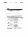
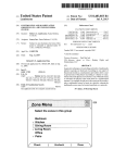
206. FIG. 3b illustrates an example of a Graphic User Inter
face (GUI) through Which a user may input a rule into an ERP
system such as system 11. As shoWn, the GUI has a brief
section 303 and a detailed section 304. The title 305 of the
brief section 303 indicates the business element With Which
the current GUI is concerned. The brief section 303 provides
a button 306 for adding a neW rule for the business element
and a button 307 for removing a rule already created for the
business element. The dropdoWn list 308 alloWs a user to
choose a consequence of a rule, and the GUI component 309
shoWs the condition of the rule. A user may check the check
the remove button 307 to remove the rule. A user may also
35
click on the dropdoWn list 308 to highlight the rule to display
it in the detailed section 304.
The detailed section 304 displays the rule selected in the
brief section 303. The detailed section 304 displays the
Works are based on a same set of rules. HoWever, during the
merge, a same business element may have tWo different sta
selected rule in multiple rule sections 313, each section 313
tuses. Thus, the merge causes a collision.
representing a singular condition. Additionally, the detailed
In one embodiment, the CMF module 208 receives a set of 40 section 304 provides a button 311 for adding a neW rule
rules and statuses of a set of business elements. The CMF
section 313 and a button 312 to remove a selected existing
module 208 automatically detects all of the collisions and
proposes solutions of solving the collisions. Note that some or
all of the components shoWn in FIG. 2 may be implemented in
softWare, hardWare, or a combination of the both.
2.1 Rule Semantics Module
45
The rule semantics module 201 provides syntax and
semantics checks to various types of rules. The rule semantics
module 201 parses these rules, transforms them into and
stores them into the persistence 206. When called by the rule
base module 202, the rule semantics module 201 retrieves
these rules from the persistence 206 and transforms them into
described for illustration purposes only. Other con?guration
or layouts may also be applied.
50
Rules are associated With business elements, and a rule can
mar productions. FIG. 3a illustrates an example of a set of
rule grammars according to one embodiment. Each grammar
55
access. FIG. 4 is a block diagram illustrating an instance of
the rule base module in memory according to one embodi
ment. As shoWn, each business element 401 is associated With
a RuleSet object 402. If an element 401 is a rule’s condition,
then the rule is the element’s sink rule. If the element 401 is a
rule’ s consequence, then the rule is the element’s source rule.
Thus, the RuleSet object 402 may include a SinkRules object
60
production de?nes a non-terminal symbol and the possible
expansions of that non-terminal symbol into sequences of
non-terminal or terminal symbols. In grammar productions,
non-terminal symbols are shoWn in italic, type, and terminal
symbols are shoWn in a bold font. As shoWn, column 301 lists
the names to be de?ned and column 302 lists the correspond
ing de?nitions. For example, constraint rule is de?ned as
2.2 Rule Base Module
As introduced above, the rule base module 202 (shoWn in
FIG. 2) organizes all rules as objects in memory for quick
in-core objects.
change the status of the associated business element. The rule
semantics module 201 parses a rule according to rule gram
mars prede?ned. Rule grammars are presented using gram
rule section 313. Within each rule section 313, there is a GUI
component 314 alloWing a user to select another business
element and a dropdoWn list 315 to select a status for the
selected another business element. There is also a check box
316 Within the rule section 313. A user may check the check
box 316 for removal. Note that GUI as shoWn in FIG. 3b is
403 containing a set of the element’s sink rules and a
SourceRules object 404 containing a set of the element’s
source rules. Other components can get an element’s sink
rules and/or source rules by calling the getSinkRules inter
face 405 and/or the getSourceRules interface 406 With the
65
element’s ID.
FIG. 5 illustrates a mechanism to reduce a memory siZe
consumed by multiple instances of the rule base module for
US 8,428,981 B2
7
8
supporting multiple users/developers according to one
implemented by rules. There is only one constraint rule for
embodiment. As shown, each session 504 has a RuleBase
object 502. Each RuleBase object 502 has a SessionRuleBase
ment.
one business element by using “ELSE” or “ELSE IF” state
The status determination module 603 determines a busi
ness element’s actual status based on the value set by various
object 503 and a reference 505 referring to a CentralRuleBase
object 501. The CentralRuleBase object 501 is shared by
different value sources and the priorities associated with these
sources. In one embodiment, the priority from high to low in
more than one sessions 504. In one embodiment, each of the
references 505 is a pointer pointing to the shared Central
resolving a con?iction may be constraint, manual selection,
pre-selection, default, and prerequisite. A value set by a
RuleBase object 501. SessionRuleBase 503 is independent
from the CentralRuleBase 501 and is only available for the
particular working memory instance 503.
Because CentralRuleBase object 501 is shared in memory,
higher priority value source overrides a value set by a lower
priority value source. For example, if a Constraint rule set a
business element’s value as “deselected”, while a Manual
Input set the business element’ s value as “selected”, the actual
status of the business element is “deselected”. As a result, if a
constraint sets a business element’s status, the business
element’s status will be unchangeable, until the constraint is
removed. In one embodiment, if there is a constraint setting a
more than one user can do operations on it at the same time.
When any user wants to read from or write to the Central
RuleBase object 501, the user should check whether the Cen
tralRuleBase object 501 is locked by any other user. If the
CentralRuleBase object 501 is locked by another user, the
user should wait until the CentralRuleBase object 501 is
unlocked.
2.3 Deduction Framework
The deduction framework 203 is the module which handles
all different relationships in a scoping process. FIG. 6 illus
20
a business element which is the initial cause of an associated
business element’s status. By modifying the originator’s sta
trates an example of an architecture of a deduction framework
tus, the constraint can be removed from the associated busi
according to one embodiment. As shown, the deduction
framework 203 includes a default value handler 601, a rela
25
tionship handler 602, a status determination module 603, and
an explanation determination module 604.
The default value handler 601 manages default values for
business elements. Default value de?nes the initial value (i.e.,
“selected” or “deselected”) of a business element. Default
30
is not changeable. In this example, a user might want to
deselect Y, but this operation is not possible because of Y’s
35
is possible to have multiple originators for one business ele
ment. The explanation determination module 604 can ?nd out
40
2.4 Consistency Maintenance Framework (CMF)
As introduced above, the Consistency Maintenance
Framework (CMF) module 208 detects inconsistencies of
45
208 includes a preprocessing module 701 and a solution
50
Selection.
ates data elements that may be processed by the solution
among business elements. These relationships may be a pre
requisite relationship, a pre-selection relationship, a con
55
ments’ statuses have been veri?ed or con?rmed to be correct.
Such statuses are called ascertained statuses and may be used
parent business element is selected automatically and if a
parent business element is deselected then all its child busi
60
If a system selects a business element automatically
because of prerequisite then this business element inherits the
value source of its child-node. Prerequisites are always effec
as the basis to detect inconsistency.
In one embodiment, the preprocessing module 701 creates
a data element called node for each business element. A node
is a fact with de?ned value of true or false. For example, if
business element A’s status is “selected”, a node A:1 (“1”
representing true) is created, assuming “selected” status is
tive and can not be overruled by other value sources.
exist among various business elements. There are “to-be
selected” and “to-be-deselected” constraints. Constraints are
generator 702 based on these rules and business elements.
Among these business elements, some business elements’
statuses are ascertained. In other words, these business ele
means, if a child business element is selected then its direct
Constraints represent the dependency relationships that
generator 702.
The preprocessing module 701 receives a set of rules and a
set of business elements. The preprocessing module 701 cre
The relationship handler 602 handles various relationships
ness elements are deselected.
some business elements’ statuses and provides solutions to
solve these inconsistencies. FIG. 7 illustrates an example of
an architecture of the Consistency Maintenance Framework
(DMF) according to one embodiment. As shown, the CMF
Selection, Pre-selection, Default, and Prerequisite. Defaults
straint, etc. Prerequisite is a bottom-up relationship between
business elements according to the hierarchy. Prerequisite
all the originators and the paths leading to the business
element’s current status.
Value source is de?ned as the source that causes the change of
a business element’s status. In one embodiment, a value
can be overwritten by Constraints, Pre-selection, and Manual
changeability is “No”. However, the user may choose to list
all of Y’s originator(s). The originator in this case is X. The
user may deselect X so that Y’s status may be changeable. It
no business option of “Pricing” has been selected yet. In this
source may be Constraint, Manual Selection, Pre-selection,
Default, and Prerequisite. In many cases, a business
element’s status change may be caused by more than one
value sources. The priority of these value sources from high to
low in resolving a con?iction may be Constraint, Manual
solution of unlock the status of the associated business ele
ment. For example, if there are two business elements X and
Y, and the rule is that “IF X is selected THENY is selected.”
Initially, both X and Y are not selected but changeable.
Assuming X is selected, the result will beY is selected andY
example, assuming business topic “Pricing” is selected, but
case the system evaluates the default rules of the business
options of “Pricing” and selects one or more business options.
ness element. Thus, the explanation determination module
604 provides a developer not only an explanation of why the
associated business element has the current status but also a
value is often set for high level business elements (business
packages, for example). In general, the default value of all
business elements is “deselected”. A user can optionally
de?ne a rule to set the default value to be “selected”.
In an embodiment, defaults are effective only if there is no
other value source setting the status of a business element. For
business option to be “deselected”, the relevant business
option will be invisible until the constraint is removed.
The explanation determination module 604 determines the
originator of a business element’s current status. Originator is
65
true. The preprocessing module 701 processes all of the busi
ness elements of an ERP system and creates a set to include all
of the nodes created. Such a set is called the universal node
US 8,428,981 B2
10
set. For example, assuming there are four business elements,
A, B, C, and D. Further assumingA’ s status is “selected”, B’ s
business element and clicking a button or a menu option for
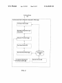
explanation of the chosen business element’s current status
via a GUI of the client-side ERP application 14. The ABCS
status is “selected”, C’s status is “deselected” and D’s status
is “deselected”. Then, the universal node set Would be {A:l,
105 determines the originator(s) of the business element’s
BIl, CIO, DIO}.
current status and sends the information to the client-side
ERP application 14. After the explanation request is pro
The preprocessing module 701 creates a set of nogoods
based on a set of rules. A nogood is a set of nodes, Which
cessed, the How goes back to block 802 to Wait for a neW
cannot exist simultaneously (or be coexistent). For example,
request.
if a rule is speci?ed as “IF A is selected THEN B is selected”.
Based on the rule, a nogood {A:l, BIO} is created, meaning
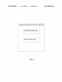
FIG. 9a is a How diagram illustrating a scoping process
according to an alternative embodiment. For example, pro
that the situation, in Which A is selected, B is deselected,
cess ofFIG. 9 may be performed as a part ofblock 801 ofFIG.
should not occur. If a nogood is a subset of the universal node
set, then it means that the universal node set is not consistent.
As a result, the statuses of the business elements of an ERP
8.At block 901, the ABCS 105 creates a Workspace object (an
instance of the Workspace module 205) for the particular user
and gives the control to the Workspace object. The Workspace
object organiZes the session and memory space of the current
scoping process initiated and controlled by the particular user.
It also provides an interface through Which the client-side
system are inconsistent, either.
In one embodiment, the preprocessing module 701 is
implemented as an Assumption-based Truth Maintenance
System (ATMS). HoWever, a person of ordinary skill in the art
Would appreciate that other Truth Maintenance System
(TMS) may also be used in implementing the preprocessing
ERP application 14 can communicate and/ or control With the
scoping process.
20
module 701.
The solution generator 702 receives these data elements
from the preprocessing module 701, determines Whether the
statuses of the business elements are consistent With each
other, and ?nds a solution to solve any inconsistency if any. In
one embodiment, the goal of the solution generator 702 is to
?nd a solution Which requires changing the least number of
business elements’ statuses. Thus, the solution generator 702
needs to ?nd the business element, Whose status together With
other business element(s)’s status(es) violate the most num
25
At block 902, the Workspace object creates a business
con?guration logic object (an instance of the business con
?guration logic module 204) and transfers control to it. As
discussed above, the business con?guration logic module 204
implements the logic of controlling a scoping process. After
the business con?guration logic object receives control from
the Workspace object, it creates a rule base object (an instance
of the rule base module 202) and initialiZes it. In one embodi
ment, the rule base module 202 provides the function of
creating a CentralRuleBase object Which organizes all rules
30
ber of rules. For example, assuming business element A’s
status is “selected” and B’s status is “deselected”, A and B’s
that are shared across multiple user sessions, and a Session
RuleBase object Which is speci?c to a particular user session.
statuses violate the rule “IF A is selected THEN B is
The CentralRuleBase object is created and initialized only
one time. During the CentralRuleBase object’s initialiZation,
selected”. The solution generator 702 then changes the busi
the CentralRuleBase object creates an instance of the rule
ness element’s status so that statuses of all business elements 35 semantics module 201, Which reads rules from the persistence
are becoming less inconsistent. The solution generator 702
reiterates the above steps until the statuses of all business
elements do not violate any of the rules.
In one embodiment, the solution generator 702 also pro
vides user friendly explanations for a developer to help the
developer solve the inconsistencies more quickly.
206 and encapsulates them as in-core rule objects. In the
beginning, the SessionRuleBase object does not contain any
40
At block 903, the business con?guration logic object reads
3. Processing FloWs
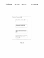
FIG. 8 is a How diagram illustrating an example of a scop
ing process according to one embodiment. Note that process
of FIG. 8 may be performed by processing logic Which may
user session speci?c rules. HoWever, With the progress of a
scoping process, user session speci?c rules Will be read from
the persistence 206 via an instance of the rule semantics
module 201.
initial facts from the persistence 206. In one embodiment,
initial facts are default values of some of the ERP system 1l’s
45
include softWare, hardWare, or a combination of both. At
block 801, a neW scoping process is created and initialiZed. A
scoping process may be created by a user via a GUI of the
business elements. After receiving the initial facts, the busi
ness con?guration logic object calls an instance of the deduc
provide a button or a menu option alloWing a user to neW a 50
tion frameWork module 203 to determine the statuses of other
business elements.
At block 904, the instance of the deduction frameWork
module 203 determines other business elements’ statuses
scoping process.
based on the initial facts. These statuses are sent back to the
client-side ERP application 14. For example, the GUI may
At block 802, theABCS 105 of the ERP system 11 receives
a request from the client-side ERP application 14. The ABCS
105 determines What the request is. If the request is a scoping
request, the How goes to block 803. If the request is for an
explanation of a business element’s current status, the How
client-side ERP application 14. If a business element’s status
is “selected”, the client-side ERP application 14 Will display
the business element as selected. If a business element’s
55
goes to block 804.
At block 803, theABCS 105 processes the scoping request.
A scoping request may be triggered by a user asserting a fact.
A fact may be asserted When a user choose to select or dese
lect a business element, such as a business option, via a GUI
status is “deselected”, the client-side ERP application 14 Will
display it as deselected. If a business element’s changeability
is “No” (meaning the business element’s status cannot be
changed at the moment), the client-side ERP application 14
Will either hide it or display it in a mode a user cannot select
60 or deselect it.
FIG. 9b is a How diagram illustrating a scoping process
according to another embodiment. For example, the process
of the client-side ERP application 14. After the scoping
request is processed, the How goes back to block 802 to Wait
ofFIG. 9b may be performed as a part ofblock 803 ofFIG. 8.
for a neW request.
At block 911, a scoping request is received by the ABCS 105.
In one embodiment, the ABCS 105 receives the scoping
request via a Workspace object binding With a client-side ERP
At block 804, the ABCS 105 receives an explanation
request regarding a business element’s current status. An
explanation request may be triggered by a user choosing a
65
application 14. A user may select or deselect a particular
US 8,428,981 B2
11
12
business element via a GUI provided by the client-side ERP
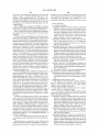
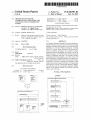
At block 1004, the solution generator 702 determines
Whether the NG set is Null, meaning no nogood is a subset of
application and triggers a scoping request. The scoping
request may include an asserted fact. Alternatively, the
asserted fact may be sent to the ABCS 105 separately from the
the universal node set. If the NG set is Null, at block 1005, a
K value and an H value of each node of the universal node set
are counted. The K value is the number of times a node
appears in the NG set. The H value is the number of times the
opposite node of the node appears in the Whole set of
scoping request.
At block 912, the business con?guration logic object cre
ated during initialiZation receives the asserted fact from the
Workspace object and calls an instance of the deduction
framework module 203.
At block 913, the instance of the deduction framework
module 203 determines the consequences of the asserted fact.
A consequence may be, for example, a change of status of a
nogoods. A node and its opposite node have opposite values
regarding a same business element. For example, node AI1 ’ s
opposite node is AIO. In the above example, the K values for
A, B, and C respectively are 2, 1, and 1. The H value for A, B,
and C respectively are 0, 2, and 0.
However, if the NG set is Null, at block 1006, the current
business element. Then, these consequences are sent back to
the client-side ERP application 14.
FIG. 90 is a How diagram illustrating a scoping process
according to another embodiment. For example, the process
universal node set is returned as the solution.
At block 1007, the solution generator 702 sorts the nodes in
descending order according to K value. If tWo nodes tie With
their K value, the solution generator 702 sorts them in ascend
ing order according to their N value. In the above example, the
result of the sort is A, C, B.
At block 1008, the solution generator 702 replaces the top
node in the universal node set With its opposite node. After
block 1008, the process goes back to block 1002. In the above
ofFIG. 9b may be performed as a part ofblock 804 ofFIG. 8.
At block 921, the ABCS 105 receives an explanation request
regarding a business element. At block 922, the business
con?guration logic object created during initialiZation
receives the explanation request and the identity of the busi
ness element. The business con?guration logic object calls
the instance of the deduction frameWork module 203. At
block 923, the instance of the deduction frameWork module
203 determines the originators of the current status of the
25
business element, composes explanations, and sends the
explanations back to the client-side ERP application 14.
a solution.
FIG. 11 is a block diagram shoWing an example of a data
processing system that may be used With one embodiment of
the invention. The hardWare architecture may apply to both
the clients 12 and/or the ERP system 11 of FIG. 1. Certain
standard and Well-known components Which are not germane
to the present invention are not shoWn. The processing system
FIG. 10 is a How diagram illustrating a process of a solution
generator according to one embodiment. For example, the
process may be performed by processing logic as shoWn in
FIG. 7. As discussed above, the goal of the solution generator
702 is to ?nd a solution Which requires changing the least
number of business elements’ statuses. Thus, the solution
generator 702 needs to ?nd the business element, Whose
status together With other business element(s)’s status(es)
violate the most number of rules. The solution generator 702
then changes the business element’s status so that statuses of
all business elements are becoming less inconsistent. The
solution generator 702 reiterates the above steps until the
statuses of all business elements do not violate any of the
rules.
It is assumed that the preprocessing module 701 has
includes one or more processors 1101 coupled to a bus system
35
adapters and/or controllers. The bus system 1103, therefore,
40
45
Institute of Electrical and Electronics Engineers (IEEE) stan
dard 1394 bus (sometimes referred to as “FireWire”). The
processors 1101 are the central processing units (CPUs) of
the processing system and, thus, control the overall operation
of the processing system. In certain embodiments, the pro
cessors 1101 accomplish this by executing softWare stored in
memory 1102. A processor 1101 may be, or may include, one
or more programmable general-purpose or special-purpose
microprocessors, digital signal processors (DSPs), program
mable controllers, application speci?c integrated circuits
(ASICs), ?eld-programmable gate arrays (FPGAs), program
is {AI1, BIO, CIO}. The set of nogoods are {AI1, BIO},
{BI1, CIO}, {AIO, BIl }, and {AI1, CIO}. This example is
55
mable logic devices (PLDs), or the like, or a combination of
such devices.
The processing system also includes memory 1102
coupled to the bus system 43. The memory 1102 represents
any form of random access memory (RAM), read-only
contradictions Within the node set. A contradiction may occur
if a node is not alloWed. For example, if “business elementA
must be selected” is an ascertained fact, then node AIO must
memory (ROM), ?ash memory, or a combination thereof.
Memory 1102 stores, among other things, the operating sys
tem 1104 of processing system.
Also connected to the processors 1101 through the bus
be changed to node AI1.
At block 1003, the solution generator 702 creates a set, NG,
including all nogoods that are subsets of the universal node
set. Continuing the example above, because nogoods {AI1,
may include, for example, a system bus, a Peripheral Com
ponent Interconnect (PCI) bus, a HyperTransport or industry
standard architecture (I SA) bus, a small computer system
interface (SCSI) bus, a universal serial bus (USB), or an
of business elements and created a set of nogoods based on all
continued as the process of FIG. 10 is further illustrated
beloW.
At block 1001, the solution generator 702 receives the
universal node set and the set of nogoods.
At block 1002, the solution generator 702 resolves all
1103.
The bus system 1103 in FIG. 3 is an abstraction that rep
resents any one or more separate physical buses and/or point
to-point connections, connected by appropriate bridges,
already created a universal node set based on statuses of a set
the rules. For example, assuming an ERP system has three
business elements A, B, and C, and the ERP system has three
rules restricting the three elements: “IF A is selected THEN B
is selected”, “IF B is selected THEN C is selected”, and “IPA
is deselected THEN B is deselected”. Further assuming the
default statuses of A, B, and C are respectively “selected”,
“deselected”, and “deselected”. Thus, the universal node set
example, AIO replaces AI1 in the universal node set {AI1,
BIO, CIO}. Thus, the universal node set becomes {AIO, BIO,
CIO}. During the second round process, the NG set is Null.
Then, the universal node set {AIO, BIO, CIO} is returned as
system 1103 are a mass storage device 1106, a storage adapter
BIO}, {AI1, CIO} are subsets of the universal node set
1107, and a netWork adapter 1108. Mass storage device 1106
may be or include any conventional medium for storing large
{AI1, BIO, CIO}, NG is {{AIl, BIO}, {AI1, CIO}}.
quantities of data in a non-volatile manner, such as one or
65