1
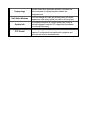
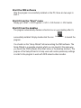
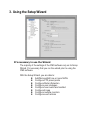
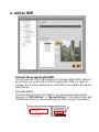
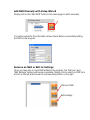
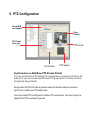
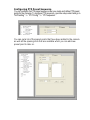
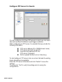
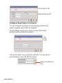
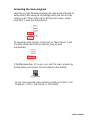
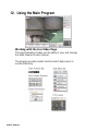
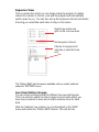
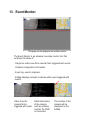
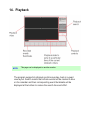
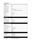
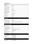
User’s Manual CV3-M1024 Central Management Software Table of Contents 1. 2. 3. 4. 5. 6. 7. 8. 9. 10. 11. 12. 13. 14. 15. 16. User Interface Overview ................................................................................................ 4 Installation ...................................................................................................................... 6 Using the Setup Wizard ............................................................................................... 10 Add an NVR .................................................................................................................. 11 PTZ Configuration ....................................................................................................... 14 Intelligent Detection Setting ........................................................................................ 18 Users and Groups ......................................................................................................... 23 Event Handling ............................................................................................................. 27 Configure E-Map ......................................................................................................... 29 Set up Multiple Monitors ............................................................................................ 33 Event Servers ................................................................................................................ 34 Using the Main Program ............................................................................................. 40 Event Monitor .............................................................................................................. 52 Playback ........................................................................................................................ 55 E-Map Monitor ............................................................................................................ 59 Service Mode ................................................................................................................ 61 U U U U U U U U U U U U U U U U U U U U U U U U U U U U U U U U U U U U U U U U U U U U U U U U U U U U U U U U U U U U U U U U Minimum System Requirements CPU Intel Core i7 or above RAM Minimum 2GB, 4GB or above is recommended HDD SATA 1TB or above is recommended Independent display card suggested Display card Note: Make sure your display DPI setting is set to default at 96DPI To set DPI value, right-click on desktop, choose “settings” tab >> “advanced” Ethernet interface OS Gigabit Ethernet card or above Windows 2000(SP4), Windows XP, Windows 2003, Windows Vista, and Windows 7 Also it does strongly recommend that close the unnecessarily programs while running CV3-M1024 (IVS Central) to monitor and record video stream from NVR or CV3. 1. User Interface Overview 0B Live Video System Log Interface Quick Access Split Video System Info Menu Bar PTZ Control Description Live Video This is where all the videos are displayed. You can decide what channels’ videos to be displayed here by dragging cameras from the side menu bar and dropping them anywhere in this section. Menu Bar This is where you can access all functions of the software. Camera list and device status information are also available from the menu bar. Quick Access Each video window comes with quick access buttons which allows you to quickly take certain actions to the video you are viewing. System Logs System status such as motion detection, functions that were accessed or settings that were altered are displayed here. Split Video Windows You can change the video split windows with you desire depends on how many videos you wish to view at a time. System Info It provides information of current system time, which is currently logged in and the CPU usage that the software is currently consuming. PTZ Control This is where you can pan, tilt, zoom the selected PTZ camera. Functions such as preset point navigation and auto pan can also be accessed here. 2. Installation 1B Begin Installation The installation should launch as soon as you insert the CD. If not, simply double-click on your CD-ROM drive icon in “My Computer” to launch the installer. Once the installer is launched, it should start by checking the compatibility with the operating system you are running this installation on. Once the compatibility check is passed, you can begin the installation by clicking “next”. The installer will install the program in a pre-defined directory. You can accept the default and click “Next” to proceed with the installation. Or you can press “Change…” to choose which location you will install this software. The installer will confirm the installation directory one more time. Click “Install” to begin installation, or click “Back” to change the installation directory. The installer will display the installation process. Once the installation is completed, click “Finish” to exit the installer. Start the CMS software After the program is successfully installed on the PC, there are two ways to start it. Start it from the “Start” menu Simply go to Start >> All Programs >> IVS >> IVS Central >> IVS Central. Start it from the desktop The program automatically creates a shortcut icon on your desktop after it’s successfully installed. Simply double-click the icon program. IVS Central.lnk to launch the You should run the “Setup Wizard” before launching the CMS software. The Setup Wizard is a separate program which you can launch it the same way you launch the CMS software (from Start menu or the desktop shortcut). The purpose of the Setup Wizard is to help users with certain preliminary settings in order for the program to work with NVR network video recorder. 3. Using the Setup Wizard 2B It’s necessary to use the Wizard The majority of the settings of the CMS software rely on its Setup Wizard. It’s necessary that you run the wizard prior to using the CMS software. With the Setup Wizard, you are able to: z Add/Remove/Edit one or more NVRs z Configure PTZ preset points z Configure Motion Detection z Configure user privileges z Configure how events are handled z Configure E-map z Configure multiple monitors z Configure event actions 4. Add an NVR 3B Connect the program with NVR The main purpose of the CMS software is to manage multiple NVRs. Before it can be done, you would need to tell the program which NVR you need it to manage. You do that by adding one or more NVRs to the program through the Setup Wizard. Automatic Search: The Setup Wizard is able to find NVR on your local network automatically. Simply go to “NVR Settings” >> “Manual Settings” in the Setup Wizard, and click the search button to locate NVRs that are placed on your local network. Drag and Drop to add Once the Setup Wizard detects NVR on the network, they will be listed in the “Detect List”. Simply drag one from the list and drop it in the “Advance Control List” below to add it. You will then be prompted with its username and password which you need to enter accordingly to complete the action. Add NVR Manually with Setup Wizard Simply click on the “Add NVR” button in the same page to add it manually. You will be asked for the information shown below before successfully adding the NVR to the program. Remove an NVR or Edit its Settings Once you have one or more NVR added to the program, the “Remove” and “Edit Settings” buttons will become available. Simply click to select an NVR from the list on the left and choose the corresponding button on the right. Remove NVR Edit settings 5. PTZ Configuration 4B Select NVR and Camera Video Preview PTZ Preset Point List PTZ Preset Point Name PTZ Speed Synchronize or Add New PTZ Preset Points You can synchronize PTZ settings from all cameras connected to NVR on the network or you can create and add new PTZ preset points to those cameras through the Setup Wizard. Simply select an NVR from the drop-down menu first and then select a camera to synchronize or add new PTZ preset points. Use the provided PTZ control panel to define a PTZ preset point. You may change the speed of the PTZ movements if you will. Video Preview You can get a video preview of the selected camera here. PTZ Speed Control Adjust the increment of the PTZ movements. PTZ Control Panel Use this panel to define a new preset point or make change to an existing one. You can get a list of the preset points that have been added to the camera as well as the opening slots that are available which you can add new preset points to later on. Slot configured with a PTZ preset point. Slot that has not been configured with a PTZ preset point. Configuring PTZ Preset Sequence You can configure the PTZ preset sequence after you create and define PTZ preset points for the cameras. To configure PTZ sequence, open the setup wizard and go to “NVR setting” >> “PTZ Config” >> “PTZ sequence”. You can get a list of the preset points that have been added to the camera as well as the opening slots that are available which you can add new preset point to later on. Select an NVR Select an NVR from the drop down menu first. Select a PTZ Camera Select a PTZ camera to configure PTZ sequence. Select Preset Points The previously configured preset points will be listed on the left. Move the ones to the right Move the preset points to the list on the right using the used for PTZ sequencing. which they will be Adjust Sequence Order or buttons to adjust the sequence orders. You can use the Set Dwell Time Finally set the dwell time for sequencing view among each point. 6. Intelligent Detection Setting 5B Intelligent Detection Functions The program can be configured with multiple intelligent detection functions which can then be used to alert users when detecting something abnormal in the scene. The functions are as below: z Motion Detection z Threat Detection z Object Loss z Tripwires To enable and configure one of the intelligent detection functions for one or more cameras, click and drag the camera from the “Device List” onto the “Intelligent Detection List”: Double click on the desired channel in the “Intelligent Detection List” to enable configuration: Finally, select the desired intelligent detection function from the “Event Mode” drop-down and make sure “Enable” is ticked: To configure a particular area for motion detection, simply click and hold down the mouse left button and move diagonally to select a desired area. You can do it repetitively to configure multiple areas for motion detection: The configured areas will then be highlighted on the video with green cell boxes: Finally, click “Submit” to save the configuration: Configuring Threat Detection This is the function that when the camera is being physically tampered (sabotaged/or viewing area gets blocked), the CMS can detect such behavior and send out alert to the administrator. To enable these factions, simply select “Malicious Attack” from the “Event Mode” dropdown menu and click “Submit”: Configuring Object Loss To select this function, select “Object Loss” from the “Event Mode” drop-down menu and then click and hold down the mouse left button and move diagonally to draw an area (select the object in the scene) for object loss detection. The selected area(s) will be highlighted in red color like shown below: Configuring Tripwire To configure tripwire, select “Tripwire” from the “Event Mode” dropdown menu. Click and hold down the mouse left button to draw a line on the video: To re-arrange the position of the line, hover the mouse cursor onto either tip end and once you see the color of the cell box becomes green, click and hold down the mouse and move the cell box to a desired new position: The tripwire function can be configuring to detect traffic coming from one way or both. Bi-directional detection is enabled by default; to configure detection for one way only, click the cell box in the middle of the line. Click again to change direction. 7. Users and Groups 6B Users and Groups Configuration The section allows users to add new users and customize each of their access privilege by assigning them to different user groups. The purpose of this function is to limit the number of people to have access to the program, hence, having access to view live videos, playback videos or altering settings of the program. Once you add users to the program, you will be prompted to enter the username and password of a valid user account. There is no user account configured for the program by default. NOTE: The privileges of the “Ad min” and the “Guest” groups are not configurable and the “Guest” account is configured with the “view only” privilege”. * Add a New User To add a new user, simply click on the “add new user” button available at the upper-right hand corner in the “User/Group config” page. Add a new user This opens up a new window for you to enter the detail information of the user you are creating. * The “Username”, “Password” and “Confirm Password” fields are required when creating a new user account. The rest of the fields are optional. * You can click the “Check” button to check if the username you are crating for the new account has been used by another account. A “+” will appear next to the group indicating a user has been added to that particular group. Click on the “+” to expand the group and all users will be displayed. The “Remove” and “Edit” buttons will become avail- able once a user has been created. Click the “Remove” button to remove an existing user, or the “Edit” button to edit setting of an existing user account Remove a user Edit setting of an existing user account Edit Group Privilege To edit access privilege of a particular user group, simply select a group first then click the “Edit Group” button. Edit privilege of a group This opens up the group privilege configuration dialog. Select a group from the drop-down menu and check which function(s) this group has permission to. Select a group Select functions to grant access to. 8. Event Handling 7B Event Handling Configuration Here you can define what constitutes an event with pre-defined conditions and what actions to be taken when these conditions are met. The conditions are divided into two categories: General event conditions Conditions such as settings being altered NVR-specific event conditions Conditions such as motion detection To enable a condition for event trigger, simply tick the checkbox of a particular condition. Event Condition Tick the checkbo x to enable Double-click pulls down the ev ent servers Event Servers Tick the checkbo x to enable Double-click on any condition pulls down the event servers which users can choose to use for that particular condition. The event servers can be considered as actions that are taken place when events are triggered. 9. Configure E-Map 8B Main Map The main map which displays locations of all NVRs Sub-maps Each sub-map displays the near-by area of a particular NVR which shows locations of all cameras connected to it The E-Map The program provides three-layered e-map which the top layer displays the location of all NVRs/NVR groups and the second layer displays locations of all NVRs that are assigned to a particular group and the third layer displays locations of all cameras that belong to a particular NVR. This function is particularly useful when motion detection is configured. You can simply place the e-map on one monitor and whenever there is motion detected, the NVR/camera will be highlighted on the map and live video will be displayed for live event monitoring. Configuring the E-Map By default, all NVRs that are added to the CSM software will be assigned to the “Main Map” group first: As more NVRs are added to the CSM software over time, you can create additional “groups” and place certain NVRs to one or more particular groups based their geographical locations for better organization. To add an additional group, click and highlight the “MainMap” group and enter a name in the “Group Name” field then click “Add”: The new group will be created and placed under the “MainMap” group first: To place one or more NVRs to the new group, simply click and drag an NVR in the list and drop it to a desired group: The NVR will be re-arranged to the group you placed it into: To change the map picture of a particular group/NVR, simply double click on it in the list or switch to the “E-map Position Assign” tab: Double-click takes you directly to the configuration page of that group under “E-map Position Assign” 1. Go to E-map Position Assign Page To replace the default map picture, double-click anywhere on the map: Double-click A new dialog should display which lets you choose the new picture for the E-map: 10. Set up Multiple Monitors 9B If you have multiple monitors configured in the PC, the CSM setup wizard can automatically detect such configuration and displays the available monitors. You can find that in the setup wizard under “General Setting”>>”Screen Layout Config”. You should then see the available monitors on the right (Screen-1, Screen2…etc). By default, all the function windows are set to display on Screen-1. You can then drag the desired function window and drop it to the monitor (ex. Screen-2) you wish it to be displayed on. 11. Event Servers 10B Event Servers are Event Actions The program provides four different event servers that can be used when events are triggered. z z z z Mail server FTP server Message server Sound server You can add up to three for each server and pick the one(s) you would like to use for particular event(s). You can get a configuration overview of all the event servers under the “Event Action Config” page. Configure Mail Server for Events You can configure up to three mail servers in which you can select later and use them for different event trigger conditions. When configuring a mail server, it’s essential that you provide the following information: z z z Mail server address (IP or FQDN domain name) Username and password for the mail server (if required) Recipient’s e-mail address To start adding a mail server, click on an item field and the setting boxes should become available. Enter the mail server information and click “Submit” to save the settings. You may click “Test” to verify the settings prior to saving the configurations. Click to add or edit Enter mail server info Configure FTP Server for Events You can configure up to three FTP servers in which you can select later and use them for different event trigger conditions. When configuring an FTP server, it’s essential that you provide the following information: FTP server address (IP or FQDN domain name) FTP server port (such as port 21) Username and password for the FTP server (if required) Path to upload the files to (if not I directory) To start adding an FTP server, click on an item field and the setting boxes should become available. Enter the FTP server information and click “Submit” to save the settings. You may click “Test” to verify the settings prior to saving the configurations. USER’S MANUAL Click to add or edit Enter mail server info Configure Message Server for Events You can configure up to three message servers in which you can select later and use them for different event trigger conditions. When configuring a message server, it’s essential that you provide the following information: z z z z Message server address (IP or FQDN domain name) Message server port Username and password for the Message server (if required) Text to be broadcasted To start adding a message server, click on an item field and the setting boxes should become available. Enter the message server information and click “Submit” to save the settings. You may click “Test” to verify the settings prior to saving the configurations. USER’S MANUAL Click to ads or edit Enter mail Server info Configure Sound Server for Events You can configure the program to send warning sound from the system’s speaker when events are triggered. To start adding a sound server, click on an item field and the setting boxes should become available. Click on the “folder” icon to locate the sound file. You may select a sound file that is only in the WAV file format. Click to locate sound file USER’S MANUAL Accessing the main program Now that you have finished configuring the mail program through its setup wizard, after saving all the settings (which you can do so by clicking on the “Save” button on the left pane tree menu), simply click “Exit” to close the Setup Wizard. To access the main program, simply click on “Main Viewer” to exit the Setup Wizard and it will be open the main program automatically. If the Main viewer does n’t run, yo u can start the main program by double-clicking on the short cut icon located on the desktop. IVS Central.lnk Or you can access the main program by simply go to Start >> All Programs >> IVS >> IVS Central >> IVS Central. USER’S MANUAL 12. Using the Main Program 11B Working with the Live Video Page This page basically provides you the ability to view, and manage the video streams of each channel. The program provides certain functions which helps users to monitor effectively. USER’S MANUAL Video Function Bar The function bar is available for each video window. The function bar provides the following functions: Interface Reconnect video Turn on/off audio Motion Detection Status Turn on/off Motion Display Take a Snapshot Description If you find the video is streamed at a lower frame rate than it should or the video is simply lost, you can click this button to re-initiate the connection with the camera and receive the stream again. If the camera supports audio function, you can click this button to receive audio from the camera. This function is turned off by default and you can only receive audio from one channel at a time. This icon serves the function to display whether motion detection has been configured for this channel. If it’s not configured, the icon is grayed out If it’s configured, it will be in light grey Once a channel is configured with motion detection, click the same icon allows you to turn on motion display which adds highlights on moving objects in the video. The icon will show in red when this function is turned on. The function allows you to take snapshots of the live video and save them on your local computer. USER’S MANUAL Simply click on the icon and the snapshot of the video will be displayed in a pop-up window. Right-click anywhere on the pop-up window will give you the option to save the snapshot. Right-Click The snapshot is automatically saved in a pre-defined folder under the directory where the program is installed. USER’S MANUAL PTZ Control Indicator You are able to control one PTZ camera at a time and this icon tells users which camera is currently selected for PTZ action. The video window will also be highlighted with blue color to indicate it’s currently being selected. PTZ icon shown in red meaning this is a PTZ camera, or it would gray out. Blue high-light. USER’S MANUAL Using PTZ Control Panel Once a video is selected for PTZ action (right-click on a video to select), you are able to do the PTZ with the PTZ control panel. Use Mouse-over-video PTZ You can simply move the mouse onto the video, an arrow and the crosshair should be displayed. Simply right-click on the video to pan / tilt the camera. Use the mouse scroll button to scroll down to zoom in and scroll up to zoom out. Right-click to pan and tilt, use mouse scroll button to zoom in/out Drag and Drop to Relocate Videos On the live view page, you can simply drag the video to re-arrange its location or switch location with an- other video. Drag a video and drop it to a new location USER’S MANUAL Drag a video and switch place with another video USER’S MANUAL View Window Switcher You can use this function to switch between different view patterns and set up how videos are displayed on the screen. Support Two Full Screen View The program supports two full screen views if there are more than one monitors connected to the PC. You can view up to 16 live video on each full screen with configurable view patterns. The first full screen displays videos in full screen with its current view pattern layout (if it’s displaying videos in a 6 split window view, the same displays in full screen). The second full screen displays videos in full screen in a 16 split window by default. You can change the layout by right-click anywhere on the screen and make selection from the drop-down menu. Side Menu Bar You can access all functions of the program from the side menu bar. Some can be displayed onto different monitors if you enabled this function in the Setup Wizard. A list of the functions available from the side menu: z z z z z z Live Monitor Event Monitor Playback E-Map Monitor NVR and Camera Status Camera Tree List z z z z z Sequence View Create patterns for different split view Service Mode Check Program Version Change Display Language Camera Tree List You can retrieve a list of the cameras and NVRs from the side menu bar. Simply click on the “TREE” menu to access this function. By default, only the NVRs are listed. You can double- click on any of them to retrieve the camera list of that NVR. You can then drag an NVR from the list and drop it onto the live video area, in which all cameras’ videos will be displayed. You can also drag one camera from the list and drop it onto any video window to display video from that camera. Drag and drop an NVR Drag and drop a camera Sequence View This is a useful tool which you can simply setup the program to display videos from certain or all cam- eras and the program will automatically switch views for you. You can also set up the sequence interval and decide how long you would like each video to stay on the screen. Select how videos are split on the live view area. Set sequence interval. Choose to sequence all cameras or selected ones only The “Pattern SEQ” will not become available until you create “patterns” under the “PATTERN” menu. Live View Pattern Groups You can create multiple profiles for different live view split layouts. This is an extreme useful function in larger environments where you have many cameras in place and multiple cameras setup for each area. After the “patterns” are created, you can head back to the “SEQ” menu and enable the “Pattern SEQ” feature. This will ask the program to display videos from the “pattern” groups in sequence. To configure view pattern groups and set it for pat- tern sequence view: 1. Select a view layout first. 2. Then, select cameras from the camera tree list. Drag and drop videos on the screen to arrange their locations as you desire. 3. Click the “+” sign under the “PATTERN” menu to add it. 4. Go back to the “SEQ” menu and select “Pattern Seq” and the patterns should be available. Select the ones for sequence viewing. 13. Event Monitor 12B This page can be displayed on another monitor The Event Monitor is an advance live video monitor tool that combines functions of: . Single live video view from camera that’s triggered with events . Channel configuration information. . Event log, search, playback. . E-Map displays cameras’ locations which were triggered with events. Video from the camera that is triggered with event Detail information of the camera, such as channel number, the NVR is connected The location of the camera will be displayed on the E-Map Playback Events from Event Monitor The program will log continuously when new events are triggered. Simply click on one to start playing back the video. Its corresponding configuration and location will also be displayed according. Playback video Channel info Camera location Click on one to start playing back an old event Filter and Search Events While the event logs keep stacking up the screen, it’s difficult to look for a particular event for playback. You can then use the search function and filter the search result by either search from an event start time, search by event type or both. Double-click to open the search dialog. You can also narrow the search results by performing search to a particular NVR. The event trigger interval is set at 10 seconds 14. Playback 13B NOTE: This page can be displayed on another monitor. The program supports 4-channel synchronous play- back in a quad view layout. Search results that include events will be marked in blue on the calendar and their corresponding event thumbnails will be displayed at the bottom to reduce the search time and effort. Searching for Playback Videos To start looking for playback videos, simply select an NVR from the drop-down menu first and select which channels to look for playbacks. Select an NVR first Select channels to perform search Search results will then be displayed on the calendar indicating which days have recordings available. Days marked in dark gray means recording available Days marked in blue means there are events being recorded Click on a day will shows what hours of that day recording were performed. Click on a particular hour to start playing back videos. If you click on an hour which event recordings were performed, the program will display the thumbnails of the first frame from each trigger at the bottom. This is useful for users to help them quickly find the footage that’s meaningful to them instead of fast- warding few times. You can also use the time bar and go directly to a particular start time. Capture Snapshots of a Playback Video This is the same function that is available in the live view page. Each playback video windows comes with function bar at the upper-right hand corner. AVI Export Current status of this channel Capture snapshot of the recorded video Turn on/off audio from the recorded video Right click on the video AVI Export You can export the recorded videos to A VI files and sa ve them onto a loc al hard dis k. Simply click on the “ AVI Export” icon while a video is being pla yed back. Click it again to stop the process. . All exported videos are automatically saved in the “AVI” folder under the program installation directory. “Ex.: C:\Program Files\IVS\CMS Central Basic\ AVI” . The program allows a maximum of one hour of video per channel to be exported. 15. E-Map Monitor 14B The E-Map provides a simple overview of where events are happening. This allows users to only pay attention to what’s meaningful to them. This function comes with two layers of maps where the first layers represent locations of each NVR. This is normally referred as the main map which a map with overview of a larger scale area should be used. Once there’s an event triggered from a particular NVR, the location of the NVR will be circled in red to notify users an event has been triggered. The video and event trigger type are also displayed on the map. Double-click on the red dot (the location of the NVR) will take you to the sub map where the locations of all the cameras within will be displayed. The camera of which the event is triggered from will be circled in red to tell the user the location of the event in a more detail manner. The sub map provides the PIP (Picture-in-Picture) view which the main map is embedded in the sub map so that users can still know if there are events being triggered from other NVRs at the same time. Sub map Main map Double-click to go back to main map Simply double-clicking the embedded main map to go back to the main map view. 16. Service Mode 15B If you are using a PC that is not dedicated to run this program only (working with some other programs at the same time). You can turn on the service mode, which can be accessed from the side menu bar under the “SYSTEM” menu, select “Service Mode”. This will minimize the program to the Windows system tray. The function to detect new NVR and event trigger notification will continually to work in the back- ground. You will get notification from the tray if the program has detected a new NVR has been placed on the network. A small video will also be pop ping out from the tr ay to notify y ou that an abnormal motion has been detected. Right-click on the program tray icon gets you other functions. z z z z z z z Maximize the program Close the main program and open the Setup Wizard Turn on/off event notification (on by default) Turn on/off NVR Smart Search (on by default) Switch to synchronize events manually (off by default) About the program Exit the program Change Program Display Language The program provides multiple languages user interface. To change the display language, go to the side menu and select “SYSTEM” >> “Language” and select a desired langu age from the drop-down menu. Check Program Version To check the program’s version, go to “SYSTEM” >> “Version”. Check Camera and NVR Status On the live view page, each camera’s current status is displayed in the upper-right hand corner of the video window. You can, however , obtain status of a ll NVRs and the camera s from the side menu under “STATUS”. Status definition