1
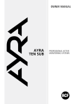
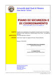
PL40 - PL6X - PL8X
DIFFUSORI A PLAFONIERA PER CONTROSOFFITTATURE
FLUSH-MOUNTING SPEAKERS FOR FALSE CEILINGS
User manual
Manuale d’uso
the rules of sound
ITALIANO
IMPORTANTE:
Prima di collegare ed utilizzare questo prodotto,
leggere attentamente le istruzioni contenute in questo manuale, il quale è
da conservare per riferimenti futuri. Il presente manuale costituisce parte
integrante del prodotto e deve accompagnare quest’ultimo anche nei
passaggi di proprietà, per permettere al nuovo proprietario di conoscere le
modalità d’installazione e d’utilizzo e le avvertenze per la sicurezza.
L’installazione e l’utilizzo errati del prodotto esimono la RCF S.p.A. da ogni
responsabilità.
ITALIANO
ATTENZIONE: Per prevenire i rischi di fiamme o scosse elettriche, non
esporre il diffusore alla pioggia o all’umidità ed alle polveri, salvo il caso
in cui questo sia stato espressamente progettato e costruito con un grado
di protezione IP adeguato (evidenziato nella documentazione tecnica del
dispositivo).
AVVERTENZE PER LA SICUREZZA
1. Tutte le avvertenze, in particolare quelle relative alla sicurezza, devono
essere lette con particolare attenzione, in quanto contengono importanti
informazioni.
2. La linea diffusori (uscita dell’amplificatore) può avere una tensione
sufficientemente alta (es. 100 V) da costituire un rischio di folgorazione
per le persone: non procedere mai all’installazione o alla connessione
del diffusore quando la linea diffusori è in tensione.
3. Assicurarsi che tutte le connessioni siano corrette e che la tensione
d’ingresso (in un sistema a tensione costante) oppure l’impedenza
del diffusore sia compatibile con le caratteristiche d’uscita
dell’amplificatore.
4. Accertarsi che la linea diffusori non possa essere calpestata o schiacciata
da oggetti, al fine di salvaguardarne la perfetta integrità.
5. Impedire che oggetti o liquidi entrino all’interno del prodotto, perché
potrebbero causare un corto circuito.
6. Non eseguire sul prodotto interventi / modifiche / riparazioni se non
quelle espressamente descritte sul manuale istruzioni.
Contattare centri di assistenza autorizzati o personale altamente
qualificato quando:
Il diffusore non funziona (o funziona in modo anomalo);
•
il cavo è danneggiato;
oggetti o liquidi sono entrati nel diffusore;
il diffusore non è più integro (a causa di urti / incendio).
7. Nel caso che dal diffusore provengano odori anomali o fumo, togliere
immediatamente la tensione dalla linea diffusori e poi scollegare il
diffusore.
8. Non collegare a questo diffusore apparecchi ed accessori non previsti.
Quando è prevista l’installazione sospesa, utilizzare solamente gli
appositi punti di ancoraggio e non cercare di appendere il diffusore con
elementi non idonei o previsti allo scopo.
Verificare inoltre l’idoneità del supporto (parete, soffitto, struttura ecc.) e
dei componenti utilizzati per il fissaggio (tasselli, viti, staffe non fornite da
RCF ecc.) che devono garantire la sicurezza dell’impianto / installazione
nel tempo, anche considerando, ad esempio, vibrazioni meccaniche
normalmente generate da un trasduttore.
9. La RCF S.p.A. raccomanda vivamente che l’installazione di questo
prodotto sia eseguita solamente da installatori professionali qualificati
(oppure da ditte specializzate) in grado di effettuarla correttamente e
certificarla in accordo con le normative vigenti.
Tutto il sistema audio dovrà essere in conformità con le norme e le
leggi vigenti in materia di impianti elettrici.
10. Vi sono numerosi fattori meccanici ed elettrici da considerare quando
si installa un sistema audio professionale (oltre a quelli prettamente
acustici, come la pressione sonora, gli angoli di copertura, la risposta in
frequenza, ecc.).
11. PERDITA DELL’UDITO
L’esposizione ad elevati livelli sonori può provocare la perdita
permanente dell’udito. Il livello di pressione acustica pericolosa per
l’udito varia sensibilmente da persona a persona e dipende dalla durata
dell’esposizione. Per evitare un’esposizione potenzialmente pericolosa
ad elevati livelli di pressione acustica, è necessario che chiunque sia
sottoposto a tali livelli utilizzi delle adeguate protezioni; quando si fa
funzionare un trasduttore in grado di produrre elevati livelli sonori è
necessario indossare dei tappi per orecchie o delle cuffie protettive.
Consultare i dati tecnici contenuti nel manuale istruzioni per conoscere
la massima pressione sonora che il diffusore acustico è in grado di
produrre.
ITALIANO
•
•
•
ITALIANO
12. I diffusori devono essere collegati in fase (corrispondenza delle
polarità +/- tra amplificatori e diffusori) in modo da garantire una corretta
riproduzione audio, soprattutto quando i diffusori sono collocati in
posizione fra loro adiacente o nello stesso ambiente.
13. Per evitare che fenomeni induttivi diano luogo a ronzii, disturbi e
compromettano il buon funzionamento dell’impianto, le linee diffusori non
devono essere canalizzate insieme ai conduttori dell’energia elettrica, ai
cavi microfonici, alle linee di segnale a basso livello che fanno capo ad
amplificatori.
14. Il cavo per il collegamento del diffusore dovrà avere conduttori di sezione
adeguata (possibilmente intrecciati, per minimizzare gli effetti induttivi
dovuti all’accoppiamento con campi elettro-magnetici circostanti) ed un
isolamento idoneo.
PRECAUZIONI D’USO
•
•
•
Collocare il diffusore lontano da fonti di calore.
Non forzare mai gli organi di comando (tasti, manopole ecc.).
Non usare solventi, alcool, benzina o altre sostanze volatili per la pulitura
delle parti esterne.
Se il diffusore viene utilizzato in ambienti particolarmente freddi, pilotarlo
con un segnale a basso livello per 5-10 minuti, prima di utilizzarlo alla
massima potenza.
•
RCF S.p.A. Vi ringrazia per l’acquisto di questo prodotto,
realizzato in modo da garantirne l’affidabilità e prestazioni
elevate.
PL40, PL6X e PL8X sono diffusori acustici a plafoniera dal design elegante
e innovativo, indicati per essere installati ad incasso in controsoffittature o
pannelli.
PL6X e PL8X impiegano rispettivamente altoparlanti da 160 mm-6” (PL6X) e
200 mm-8” (PL8X) entrambi con tweeter coassiale da 25 mm (1”) montato
su un supporto a ponte. PL40 impiega un altoparlante a gamma estesa
da 86 mm-3,5”. I diffusori sono corredati di un trasformatore di linea che
consente il collegamento diretto ad impianti a tensione costante a 70 V o 100
V. Grazie alle prese multiple del trasformatore di linea è possibile selezionare
la potenza da diffondere fra diversi valori disponibili.
L’installazione a soffitto è semplice e veloce grazie ad un particolare sistema
a tre ganci rotanti che evita l’impiego di viti e tasselli o altri elementi di
fissaggio.
Il diffusore è stato studiato per essere installato ad incasso in controsoffittature.
Prima dell’installazione verificare che dietro al controsoffitto vi sia uno spazio
sufficiente per accogliere il diffusore: rispetto al piano di appoggio della
flangia frontale del diffusore è necessario uno spazio libero in profondità di
almeno 90 mm (3.46”) per PL8X e 75 mm (2.87”) per PL6X e 110 mm
(4.33”) per il diffusore PL40.
1. Praticare un foro del diametro Ø di 224 mm (8.82”) per PL8X e 182 mm
(1.17”) per PL6X e 122 mm per PL40 nella controsoffittatura, nel punto
prescelto per l’installazione del diffusore.
2. Inserire il diffusore nel foro praticato, come indicato al punto 1 di Fig.1.
3. Avvitare le 3 viti che stringono i 3 morsetti di bloccaggio A del diffusore,
come indicato al punto 2 di Fig.1 fino a che la flangia esterna aderisce
al soffitto.
4. Incastrare la rete metallica di protezione nella parte frontale del diffusore,
come indicato al punto 3 di Fig.1. Utilizzare i feltrini adesivi, se disponibili,
per garantire il fissaggio della rete.
Ø
Fig. 1
ITALIANO
NELL’UTILIZZO ALL’APERTO EVITARE LUOGHI ESPOSTI ALLE INTEMPERIE.
ITALIANO
COLLEGAMENTI
Per evitare il rischio di shock elettrici, non collegare il diffusore con
l’amplificatore acceso.
Prima di far funzionare il diffusore verificare attentamente la correttezza dei
collegamenti, per evitare che cortocircuiti accidentali possano dare luogo a
scintille elettriche.
Il diffusore può essere collegato a linee audio a tensione costante a 70 V o
100 V. I collegamenti si effettuano tramite la morsettiera d’ingresso a 6 poli,
presente nella parte posteriore del diffusore.
1. Individuare i conduttori d’ingresso da utilizzare.
COLLEGAMENTO DEI DIFFUSORI ACUSTICI
PL 40
conduttore
GIALLO
VERDE
BLU
ROSSO
NERO
70 V
4W
3W
2W
1W
COM (–)
100 V
8W
6W
4W
2W
PL 6X
conduttore
VERDE
BIANCO
MARRONE
BLU
GIALLO
NERO
70 V
12 W
6W
3W
1.5 W
---
COM (–)
100 V
---
12 W
6W
3W
1.5 W
conduttore
GIALLO
BIANCO
VERDE
BLU
MARRONE
NERO
70 V
20 W
10 W
5W
2.5 W
---
COM (–)
100 V
---
20 W
10 W
5W
2.5 W
PL 8X
2. Collegare il conduttore NERO del diffusore al conduttore “negativo” (-)
della linea audio, che fa capo al morsetto dell’amplificatore contrassegnato
con 0 o COM.
3. Collegare l’altro conduttore del diffusore, precedentemente individuato
tramite la legenda, al conduttore “positivo” (+) della linea audio.
IMPORTANTE: Per evitare di danneggiare il diffusore e l’amplificatore,
non utilizzare mai il conduttore corrispondente alla potenza massima a
70 V quando il diffusore viene alimentato con linee a 100 V.
4. Per evitare il rischio di shock elettrici collocare la morsettiera d’ingresso
in una posizione inaccessibile. Effettuare le connessioni tenendo in
considerazione le seguenti indicazioni (fig.2 nella pagina successiva).
•
•
ITALIANO
•
la tensione d’ingresso selezionata sul diffusore deve corrispondere con
la tensione selezionata sull’uscita dell’amplificatore.
la somma delle potenze di utilizzo di tutti i diffusori collegati alla linea
audio non deve superare quella dell’amplificatore.
per garantire una corretta riproduzione audio effettuare un collegamento
“in fase”, che consiste nel fare corrispondere le polarità +/- dell’uscita
dell’amplificatore con le polarità +/- dell’ingresso del trasformatore.
Quando due diffusori riproducono le medesime frequenze ma con differenze
di fase, esiste la possibilità che tali frequenze si annullino. Spesso negli
impianti di sonorizzazione i diffusori vengono collocati in posizioni fra loro
adiacenti, e le onde sonore prodotte interagiscono fra loro; se un diffusore
viene collegato in modo errato, ossia viene invertita la polarità dei conduttori
della linea audio, i segnali audio vengono diffusi con differenze di fase, e la
corretta riproduzione viene quindi compromessa.
Fig. 2
Amplificatore
Pa > Pd x n
+
-
Va
-
+
Vd = Va
-
+
-
Vd = Va
+
Vd = Va
Pa = Potenza amplificatore
Pd = Potenza diffusore
n = Numero diffusori
Vd = Tensione ingresso diffusore
Va = Tensione uscita amplificatore
CAVI D’INGRESSO
Per il collegamento del diffusore utilizzare dei cavi aventi un’adeguata
sezione. Maggiore è la distanza fra l’amplificatore ed il diffusore, e maggiore
dovrebbe essere la sezione dei cavi di collegamento, questa per limitare le
perdite di segnale lungo la linea. Per evitare che fenomeni induttivi diano
luogo a ronzii, disturbi, e compromettano il buon funzionamento dell’impianto
audio, i cavi per diffusori non devono essere canalizzati assieme ai conduttori
dell’energia elettrica, ai cavi microfonici, o a linee audio a basso livello (es.
livello LINEA). Per facilitare il collegamento “in fase” del diffusore, utilizzare
cavi bipolari aventi una marcatura che ne distingua le polarità (es. isolante di
colore diverso, conduttori di colore diverso, ecc.).
Per minimizzare gli effetti induttivi (ronzii) dovuti all’accoppiamento con campi
elettrici circostanti, utilizzare cavi con i conduttori intrecciati fra loro.
ITALIANO
SPECIFICHE TECNICHE - PL8X
SISTEMA ACUSTICO
Trasduttori
Potenza nominale/massima
Gamma di frequenza:
Angolo di copertura in funzione
dell’intelligibilità vocale (-6dB):
Fattore di direttività Q (DI):
Sensibilità :
Massima pressione sonora (SPL):
Impedenza:
Altoparlante 8” con tweeter coassiale.
20/40W
60 Hz – 20 kHz
Tensione d’ingresso:
Potenze selezionabili:
70V,100V
70 V: 2,5 W- 5 W – 10 W- 20 W
100 V: 2,5 W- 5 W – 10 W – 20 W
80°
11 (10)
93 dB a 1 W 1 m
109 dB 1m alla potenza massima
70V-20W : 250 ohm
100V-20W/70V-10W : 500 ohm
100V-10W/70V-5W : 1000 ohm
100V-5W/70V-2,5W : 2000 ohm
100V-2,5 W : 4000 ohm
CARATTERISTICHE FISICHE
Materiali:
Sistema di fissaggio:
Ingressi:
Dimensioni (Ø x H):
Foro per incasso:
Peso netto:
spessore min./max. soffitto:
Sporgenza massima:
Protezione:
Corpo principale in materiale plastico,
rete frontale in acciaio
ad incasso
Morsettiera a 6 poli
247 x 88 mm
224 mm
1,8 kg
8/30 mm
8 mm
IP44
SISTEMA ACUSTICO
Trasduttori
Potenza nominale/massima
Gamma di frequenza:
Angolo di copertura in funzione
dell’intelligibilità vocale (-6dB):
Fattore di direttività Q (DI):
Sensibilità :
Massima pressione sonora (SPL):
Impedenza:
Altoparlante 6” con tweeter coassiale
12/24 W
70 Hz – 20 kHz
Tensione d’ingresso:
Potenze selezionabili:
70V,100V
70 V: 12-6-3-1,5 W
100 V: 12-6-3-1,5 W
100°
9 (9,5)
92 dB a 1 W 1 m
106 dB 1m alla potenza massima
70V-12W : 400 ohm
100V-12W / 70V-6W : 800 ohm
100V-6W / 70V-3W : 1600 ohm
100V-3W / 70V-1,5W : 3300 ohm
CARATTERISTICHE FISICHE
Materiali:
Sistema di fissaggio:
Ingressi:
Dimensioni (Ø x H):
Foro per incasso:
Peso netto:
spessore min./max. soffitto:
Sporgenza massima:
Protezione:
Corpo principale in materiale plastico,
rete frontale in acciaio
ad incasso
Morsettiera a 6 poli
204 x 73 mm
182 mm
1,2 kg
8/30 mm
7 mm
IP44
ITALIANO
SPECIFICHE TECNICHE - PL6X
ITALIANO
SPECIFICHE TECNICHE - PL40
SISTEMA ACUSTICO
Trasduttori
Potenza nominale/massima
Gamma di frequenza:
Angolo di copertura in funzione
dell’intelligibilità vocale:
Fattore di direttività Q (DI):
Sensibilità :
Massima pressione sonora (SPL):
Impedenza:
altoparlante 3,5” gamma estesa
8/16 W
90 Hz - 20kHz
Tensione d’ingresso:
Potenze selezionabili:
100V, 70V
100V: 8-6-4-2 W
70V : 4-3-2-1 W
120°
8 (9)
88 dB
100 dB 1m alla potenza massima
100V-8W/70V-4W : 1250 ohm
100V-6W/70V-3W : 1670 ohm
100V-4W/70V-2W : 2500 ohm
100V-2W/70V-1W : 5000 ohm
CARATTERISTICHE FISICHE
Materiali:
Sistema di fissaggio:
Ingressi:
Dimensioni (Ø x H):
Foro per incasso:
Peso netto:
spessore min./max. soffitto:
Sporgenza massima:
Protezione:
10
Corpo principale in materiale plastico,
rete frontale in acciaio
ad incasso
Morsettiera a 5 poli
130 x 110 mm
122 mm
1,0 kg
4/24 mm
7 mm
IP44
IMPORTANT NOTES:
Before connecting and using this product,
please read this instruction manual carefully and keep it on hand for future
reference. The manual is to be considered an integral part of this product
and must accompany it when it changes ownership as a reference for correct
installation and use as well as for the safety precautions.
RCF S.p.A. will not assume any responsibility for the incorrect installation and
/ or use of this product.
loudspeaker to rain or humidity and dust, but the case this has been expressly
designed and made to get a suitable IP protection grade (indicated in the
product specifications).
SAFETY PRECAUTIONS
1. All the precautions, in particular the safety ones, must be read with
special attention, as they provide important information.
2. Loudspeaker lines (amplifier outputs) can have a sufficiently high voltage
(i.e. 100 V) to involve a risk of electrocution: never install or connect this
loudspeaker when the line is alive.
3. Make sure all connections have been made correctly and the loudspeaker
input voltage (in a constant voltage system) or its impedance is suitable
for the amplifier output.
4. Protect loudspeaker lines from damage; make sure they are positioned
in a way that they cannot be stepped on or crushed by objects.
5. Make sure that no objects or liquids can get into this product, as this may
cause a short circuit.
6. Never attempt to carry out any operations, modifications or repairs that
are not expressly described in this manual.
Contact your authorized service centre or qualified personnel should any
of the following occur:
• the loudspeaker does not function (or works in an anomalous way);
• the cable has been damaged;
• objects or liquids have got into the unit;
• the loudspeaker has been damaged due to heavy impacts / fire.
11
ENGLISH
WARNING: To prevent the risk of fire or electric shock, never expose this
7. Should the loudspeaker emit any strange odours or smoke, remove it
from the line after having switched the amplifier off.
8. Do not connect this product to any equipment or accessories not
ENGLISH
foreseen.
For suspended installation, only use the dedicated anchoring points and
do not try to hang this loudspeaker by using elements that are unsuitable
or not specific for this purpose.
Also check the suitability of the support surface to which the product
is anchored (wall, ceiling, structure, etc.), and the components used
for attachment (screw anchors, screws, brackets not supplied by RCF
etc.), which must guarantee the security of the system / installation over
time, also considering, for example, the mechanical vibrations normally
generated by transducers.
9. RCF S.p.A. strongly recommends this product is only installed by
professional qualified installers (or specialised firms) who can ensure a
correct installation and certify it according to the regulations in force.
The entire audio system must comply with the current standards and
regulations regarding electrical systems.
10. There are numerous mechanical and electrical factors to be considered
when installing a professional audio system (in addition to those which
are strictly acoustic, such as sound pressure, angles of coverage,
frequency response, etc.).
11. HEARING LOSS
Exposure to high sound levels can cause permanent hearing loss. The
acoustic pressure level that leads to hearing loss is different from person
to person and depends on the duration of exposure. To prevent potentially
dangerous exposure to high levels of acoustic pressure, anyone who is
exposed to these levels should use adequate protection devices. When
a transducer capable of producing high sound levels is being used, it is
therefore necessary to wear ear plugs or protective earphones.
See the technical specifications in the instruction manual for the maximum
sound pressure the loudspeaker is capable of producing.
12. To ensure a correct musical reproduction, loudspeaker phase is to
be respected (loudspeakers are connected respecting the amplifier
polarity). This is important when loudspeakers are installed adjacent one
another, for instance, in the same room.
13. To prevent inductive effects from causing hum, noise and a bad system
12
working, loudspeaker lines should not be laid together with other electric
cables (mains), microphone or line level signal cables connected to
amplifier inputs.
14. The loudspeaker cable shall have wires with a suitable section (twisted, if
possible, to reduce inductive effects due to surrounding electro-magnetic
fields) and a sufficient electrical insulation.
• Install this loudspeaker far from any heat source.
• Never force the control elements (keys, knobs, etc. ).
• Do not use solvents, alcohol, benzene or other volatile substances for
cleaning the external parts of this product.
• If the speaker is used in particulary cold places, drive it with a low signal
for 5-10 minutes before using it at maximum power.
RCF S.p.A. would like to thank you for having purchased this
product, which has been designed to guarantee reliability and
high performance.
PL40, PL6X and PL8X are ceiling speakers featuring elegant and innovative
design that can be flush-mounted in false ceilings or panels.
PL6X incorporate a 160 mm (6”) and PL8X a 200 mm (8”) loudspeaker. Both
have a coaxial 25 mm (1”) tweeter placed on a bridge support.
PL40 incorporate an 86 mm-3.5” a full range speaker. The speakers are
equipped with a line transformer that enables direct connection to constant
voltage systems at 70 V or 100 V. The multiple sockets on the transformer
make it possible to select the output power from among several values.
Installation is quick and easy thanks to a special three-hook system that
avoids the need for using screws and pallet or other attachment elements.
13
ENGLISH
OPERATING PRECAUTIONS
IN OUTDOOR USE, AVOID INSTALLING THE SPEAKER IN PLACES EXPOSED
TO HARSH WEATHER CONDITIONS.The speaker is designed for flush-mount
ENGLISH
installation in false ceilings. Before installing the speaker, make sure that there
is sufficient space behind the false ceiling panel to hold the speaker: with
respect to the support surface of the front flange of the speaker, a free space
of 90 mm (3.46”) for PL8X and 75 mm (2.87”) for PL6X depth is necessary
110 mm (4.33”) for the PL40 speaker.
1. Drill a hole of diameter Ø 224 mm (8.82”) for PL8X and 182 mm (1.17”)
for PL6X and 122 mm for PL40 in the false ceiling at the point chosen for
installing the speaker.
2. Insert the speaker in the hole as shown in Fig. 1 - point 1.
3. Screw in the three screws that tighten the three attachment terminals A
of the speaker, as shownin Fig. 1 - point 2 until the external flange touch
the ceiling.
4. Fit the metal protective mesh onto the front of the speaker as shown in
Fig. 1 - point
clamping.
3. Use the adhesive felt, if available, to guarantee the grill
Ø
14
Fig. 1
CONNECTIONS
To prevent the risk of electric shock, do not connect the speaker with the
amplifier switched on.
1.Locate the input conductors to be used.
LOUDSPEAKER CONNECTION
PL 40
wire
YELLOW
GREEN
BLUE
RED
BLACK
70 V
4W
3W
2W
1W
COM (–)
100 V
8W
6W
4W
2W
PL 6X
wire
GREEN
WHITE
BROWN
BLUE
YELLOW
BLACK
70 V
12 W
6W
3W
1.5 W
---
COM (–)
100 V
---
12 W
6W
3W
1.5 W
wire
YELLOW
WHITE
GREEN
BLUE
BROWN
BLACK
70 V
20 W
10 W
5W
2.5 W
---
COM (–)
100 V
---
20 W
10 W
5W
2.5 W
PL 8X
2. Connect the BLACK conductor of the speaker to the “negative” conductor
(-) of the audio line that leads from the amplifier terminal marked -, 0, or
COM.
3.Connect the other speaker conductor located using the legend to the
“positive” conductor (+) of the audio line.
VERY IMPORTANT: To prevent speaker damage, never use the maximum
power at 70 V conductor when the speaker or the amplifier is supplied with
100 V lines.
4.To prevent the risk of electric shock, situate the terminal strip in an
inaccessible position (e.g. inside the speaker when it is used with the
accessory for surface mount installation). When making the connections,
keep the following indications in mind (Fig. 2 “next page”).
15
ENGLISH
Before using the speaker, carefully check that all the connections have been
made correctly to make sure there are no accidental short circuits that could
cause electrical sparks.
The speaker can be connected to constant voltage audio lines at 70 V or 100
V. Connections are made using the 6-pin input terminal strip on the rear part
of the speaker.
• The input voltage selected on the speaker must correspond with the
voltage selected on the amplifier.
• The sum of the operating power values of all the speakers connected to
the audio line must not exceed that of the amplifier.
• To ensure correct audio reproduction, the connections should be made “in
phase”, where the +/- polarities of the amplifier output correspond with the
+/- polarities of the speaker input.
ENGLISH
When two speakers reproduce the same frequencies but with phase
differences, these frequencies may be annulled. In sound systems, speakers
are often situated in adjacent positions and the sound waves produced
interact with each other. If a speaker is connected incorrectly; i.e. the polarity
of the audio line conductors is inverted, the audio signals are transmitted with
differences in phase and correct reproduction is therefore jeopardized.
Fig. 2
Amplifier
+
Pa > Pd x n
Va
-
+
Vd = Va
-
+
Vd = Va
-
+
Vd = Va
Pa = Amplifier power
Pd = Speaker power
n = Number of speakers
Vd = Speaker input voltage
Va = Amplifier output voltage
INPUT CABLES
For connecting the speaker use cables with an adequate cross-section.
The greater the distance between the amplifier and the speaker, the larger
the connection cable cross-section should be to limit the voltage loss along
the line. To prevent inductive phenomena from giving rise to humming or
disturbance that jeopardize the effective operation of the audio system, the
speaker cables should not be run together with electrical energy conductors,
microphone cables, or low level audio lines (e.g. LINE level).
To facilitate the ‘’in phase’’ connection of the speaker, use bipolar cables that
have markings to distinguish the polarity (e.g. insulation of different colours,
conductors of different colours, ect.).
To minimize the inductive effects (hum) due to coupling with surrounding
electrical fields, use cables with conductors braided together.
16
SPECIFICATIONS - PL8X
ACOUSTIC SYSTEM
Input Voltage:
Selectable power values:
8” woofer with coaxial tweeter
20/40W
60 Hz – 20 kHz
80°
11 (10)
93 dB a 1 W 1 m
109 dB 1m at program power
70V-20W : 250 ohm
100V-20W/70V-10W : 500 ohm
100V-10W/70V-5W : 1000 ohm
100V-5W/70V-2,5W : 2000 ohm
100V-2,5 W : 4000 ohm
70V,100V
70 V: 2,5 W- 5 W – 10 W- 20 W
100 V: 2,5 W- 5 W – 10 W – 20 W
PHYSICAL
CHARACTERISTICS
Material:
Attachment system:
Inputs:
Dimensioni (Ø x H):
Flush mount hole:
Net weight :
Min/max ceiling thickness:
Maximum tailing:
Protection:
Main body in plastic material,
steel grille
Flush mount
6 pin terminal block
247 x 88 mm
224 mm
1,8 kg
8/30 mm
8 mm
IP44
17
ENGLISH
Transducers
Nominal/maximum power
Frequency range:
Dispersion angle as function of vocal
intelligibility (-6dB):
Directivity factor Q (DI):
Sensitivity :
SPL at program power:
Impedance:
SPECIFICATIONS - PL6X
ENGLISH
ACOUSTIC SYSTEM
Transducers
Nominal/maximum power
Frequency range:
Dispersion angle as function of vocal
intelligibility (-6dB):
Directivity factor Q (DI):
Sensitivity :
SPL at program power:
Impedance:
6” woofer with coaxial tweeter
12/24 W
70 Hz – 20 kHz
Input Voltage:
Selectable power values:
70V,100V
70 V: 12-6-3-1,5 W
100 V: 12-6-3-1,5 W
100°
9 (9,5)
92 dB a 1 W 1 m
106 dB 1m at program power
70V-12W : 400 ohm
100V-12W / 70V-6W : 800 ohm
100V-6W / 70V-3W : 1600 ohm
100V-3W / 70V-1,5W : 3300 ohm
PHYSICAL CHARACTERISTICS
Material:
Attachment system:
Inputs:
Dimensioni (Ø x H):
Flush mount hole:
Net weight :
Min/max ceiling thickness:
Maximum tailing:
Protection:
18
Main body in plastic material,
steel grille
Flush mount
6 pin terminal block
204 x 73 mm
182 mm
1,2 kg
8/30 mm
7 mm
IP44
SPECIFICATIONS - PL40
ACOUSTIC SYSTEM
3.5” full range speaker
8/16 W
90 Hz - 20kHz
Input Voltage:
Selectable power values:
100V, 70V
100V: 8-6-4-2 W
70V : 4-3-2-1 W
120°
8 (9)
88 dB 100 dB 1m at program power
100V-8W/70V-4W : 1250 ohm
100V-6W/70V-3W : 1670 ohm
100V-4W/70V-2W : 2500 ohm
100V-2W/70V-1W : 5000 ohm
PHYSICAL CHARACTERISTICS
Material:
Attachment system:
Inputs:
Dimensioni (Ø x H):
Flush mount hole:
Net weight :
Min/max ceiling thickness:
Maximum tailing:
Protection:
Main body in plastic material,
steel grille
Flush mount
5 pin terminal block
130 x 110 mm
122 mm
1,0 kg
4/24 mm
7 mm
IP44
19
ENGLISH
Transducers
Nominal/maximum power
Frequency range:
Dispersion angle as function of vocal
intelligibility:
Directivity factor Q (DI):
Sensitivity :
SPL at program power:
Impedance:
Salvo eventuali errori ed omissioni.
RCF S.p.A. si riserva il diritto di apportare modifiche senza preavviso.
Except possible errors and omissions.
RCF S.p.A. reserves the right to make modifications without prior notice.
10307083
10307043/D
the rules of sound
RCF SpA: Via Raffaello, 13 - 42100 Reggio Emilia > Italy
tel. +39 0522 274411 - fax +39 0522 274484 - e-mail: [email protected]