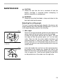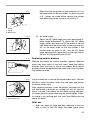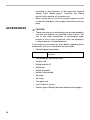
1
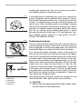
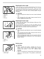
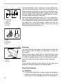
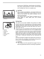
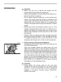
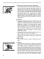
ENGLISH
Cordless Slide
Compound Saw
Equipped with Electric Brake
190 mm
MODEL LS711D
002214
I N S T R U C T I O N
M A N U A L
WARNING:
For your personal safety, READ and UNDERSTAND before using.
SAVE THESE INSTRUCTIONS FOR FUTURE REFERENCE.
SPECIFICATIONS
Blade diameter : ............................................................................................. 180 - 190 mm
Hole (arbor) diameter : .............................................................................................. 20 mm
Max. Miter angle : ....................................................................................Left 47°, Right 57°
Max. Bevel angle : ....................................................................................................Left 45°
Max. Cutting capacities (H x W) with blade 190 mm in daiameter.
Miter angle
Bevel angle
0°
45° (left)
0°
50 mm x 182 mm
35 mm x 182 mm
45° (left and right)
50 mm x 127 mm
35 mm x 127 mm
(Note)
The max. Cutting capacities may vary according to workpiece, blade and/or charging condition.
No load speed : ..................................................................................................2,000 min.-1
Dimensions (L x W x H) : ...................................................... 550 mm x 430 mm x 454 mm
Net weight : ............................................................................................................... 10.5 kg
• Manufacturer reserves the right to change specifications without notice.
• Specifications may differ from country to country.
Intended use
The tool is intended for accurate straight and miter cutting in wood.
SYMBOLS
END303-1
The following show the symbols used for the tool. Be sure that you understand their meaning before use.
................. Indoor use only
................ Read instruction manual.
.................. DOUBLE INSULATION
.......... Ready to charge
............. Charging
2
.............Charging complete
......................Delay charge (too hot battery)
.........Deffective battery
................. Do not short batteries.
....... Always recycle batteries.
................ Do not discard batteries into
garbage can or the like.
................To avoid injury from flying
debris, keep holding the saw
head down, after making cuts,
until the blade has come to a
complete stop.
...............For your safety, remove the
chips, small pieces, etc. from the
table top before operation.
NOTE:
The recycling method may differ from country to country, or state (province) to state (province). Consult with your nearest Makita Authorized Service Center or Distributor.
SAFETY INSTRUCTIONS
ENA002-1
WARNING:
When using battery operated tools basic safety precautions,
including the following, should be followed to reduce the risk of
fire, leaking batteries and personal injury: Read these
instructions before operating this product and save these
instructions.
For safe operation:
1. Keep work area clean. Cluttered areas and
benches invite injuries.
2. Consider the work environment. Do not
expose the tool to rain. Keep work area well
lit. Do not use tools in the presence of flammable liquids or gases.
3. Keep children away. Do not let visitors touch
the tool. Keep visitors away from work area.
4. Store batteries or idle tools. When not in
use, tools and batteries should be stored
separately in a dry, high or locked up place,
out of reach of children. Ensure that battery
terminals cannot be shorted by other metal
parts such as screws, nails, etc.
5. Do not force the tool. It will do the job better
and safer at the rate for which it was
intended.
6. Use the right tool. Do not force small tools
or attachments to do the job of a heavy duty
tools. Do not use tools for purposes not
intended.
7. Dress properly. Do not wear loose clothing
or jewellery, they can be caught in moving
parts. Non-skid footwear is recommended
when working outdoors. Wear protecting hair
covering to contain long hair.
8. Use protective equipment. Use safety
glasses and if the cutting operation is dusty, a
face or dust mask.
9. Connect dust extraction equipment. If
devices are provided for the connection of
3
dust extraction and collection ensure these
are connected and properly used.
10. Do not abuse the supply cord ( if fitted ).
Never carry the tool by the cord or yank it to
disconnect from the socket. Keep the cord
away from heat, oil and sharp edges.
11. Secure the work. Use clamps or a vice to
hold the work. It is safer than using your hand
and it frees both hands to operate the tool.
12. Do not over-reach. Keep proper footing and
balance at all times.
13. Maintain tools with care. Keep cutting tools
sharp and clean for better and safer performance. Follow instructions for lubrication and
changing accessories. Inspect tool cords
periodically and if damaged have repaired by
an authorized service facility.
14. Disconnect tools. Where the design permits, disconnect the tool from its battery pack
when not in use, before servicing and when
changing accessories such as blades, bits
and cutters.
15. Remove adjusting keys and wrenches.
Form the habit of checking to see that keys
and adjusting wrenches are removed from
the tool before turning it on.
16. Avoid unintentional starting. Do not carry
the tool with a finger on the switch.
17. Stay alert. Watch what you are doing. Use
common sense. Do not operate the tool when
you are tired.
18. Check damaged parts. Before further use of
the tool, a guard or other part that is damaged should be carefully checked to determine that it will operate properly and perform
its intended function. Check for alignment of
moving parts, free running of moving parts,
breakage of parts, mounting and any other
condition that may affect its operation. A
guard or other part that is damaged should
be properly repaired or replaced by an
authorized service facility unless otherwise
indicated in this instruction manual. Have
4
defective switches replaced by an authorized
service facility. Do not use the tool if the
switch does not turn it on and off.
19. Warning. The use of any accessory or
attachment, other than recommended in this
instruction manual or the catalog, may
present a risk of personal injury. Ensure that
the battery pack is correct for the tool. Ensure
that the outside surface of battery pack or
tool is clean and dry before plugging into
charger. Ensure that batteries are charged
using the correct charger recommended by
the manufacturer. Incorrect use may result in
a risk of electric shock, overheating or leakage of corrosive liquid from the battery.
20. Have your tool repaired by a qualified person. This tool is constructed in accordance
with the relevant safety requirements.
Repairs should only be carried out by qualified persons using original spare parts, otherwise this may result in considerable danger to
the user.
21. Disposal of battery. Ensure battery is disposed of safety as instructed by the manufacturer.
ADDITIONAL SAFETY RULES FOR TOOL
ENB035-2
1. Be aware that this tool is always in an
operating condition, because it does not
have to be plugged into an electrical outlet.
14. Be careful not to damage the arbor,
flanges (especially the installing surface)
or bolt. Damage to these parts could
result in blade breakage.
2. Wear eye protection.
15. Make sure that the turn base is properly
secured so it will not move during operation.
3. Keep hands out of path of saw blade.
Avoid contact with any coasting blade. It
can still cause severe injury.
4. Do not operate saw without guards in
place. Check blade guard for proper closing before each use. Do not operate saw if
blade guard does not move freely and
close instantly. Never clamp or tie the
blade guard into the open position.
5. Do not perform any operation freehand.
The workpiece must be secured firmly
against the turn base and guide fence with
the vise during all operations. Never use
your hand to secure the workpiece.
6. Never reach around saw blade.
7. Turn off tool and wait for saw blade to
stop before moving workpiece or changing settings.
8. Remove battery from tool before changing
blade or servicing.
9. Always secure all moving portions before
carrying the tool.
10. Stopper pin which locks the cutter head
down is for carrying and storage purposes only and not for any cutting operations.
11. Don’t use the tool in the presence of flammable liquids or gases.
12. Check the blade carefully for cracks or
damage before operation.
Replace cracked or damaged blade immediately.
13. Use only flanges specified for this tool.
16. For your safety, remove the chips, small
pieces, etc. from the table top before operation.
17. Avoid cutting nails. Inspect for and
remove all nails from the workpiece
before operation.
18. Make sure the shaft lock is released
before the switch is turned on.
19. Be sure that the blade does not contact
the turn base in the lowest position.
20. Hold the handle firmly. Be aware that the
saw moves up or down slightly during
start-up and stopping.
21. Make sure the blade is not contacting the
workpiece before the switch is turned on.
22. Before using the tool on an actual workpiece, let it run for a while. Watch for
vibration or wobbling that could indicate
poor installation or a poorly balanced
blade.
23. Wait until the blade attains full speed
before cutting.
24. Stop operation immediately if you notice
anything abnormal.
25. Do not attempt to lock the trigger in the on
position.
26. Be alert at all times, especially during
repetitive, monotonous operations. Don’t
be lulled into a false sense of security.
Blades are extremely unforgiving.
27. Always use accessories recommended in
this manual. Use of improper accessories
5
such as abrasive wheels may cause an
injury.
28. Do not use the saw to cut other than wood
or similar materials.
30. Select saw blades in relation to the material to be cut.
31. Take care when slotting.
32. Replace the kerf board when worm.
29. Connect miter saws to a dust collecting
device when sawing.
SAVE THESE INSTRUCTIONS
IMPORTANT SAFETY INSTRUCTIONS FOR
CHARGER & BATTERY CARTRIDGE
1. SAVE THESE INSTRUCTIONS- This manual contains important safety and operating instructions for battery charger.
2. Before using battery charger, read all
instructions and cautionary markings on
(1) battery charger, (2) battery, and (3)
product using battery.
3. CAUTION - To reduce risk of injury, charge
only MAKITA type rechargeable batteries.
Other types of batteries may burst causing personal injury and damage.
4. Do not expose charger to rain or snow.
5. Use of an attachment not recommended
or sold by the battery charger manufacturer may result in a risk of fire, electric
shock, or injury to persons.
6. To reduce risk of damage to electric plug
and cord, pull by plug rather than cord
when disconnecting charger.
7. Make sure cord is located so that it will
not be stepped on, tripped over, or otherwise subjected to damage or stress.
6
ENC001-3
8. Do not operate charger with damaged
cord or plug - replace them immediately.
9. Do not operate charger if it has received a
sharp blow, been dropped, or otherwise
damaged in any way; take it to a qualified
serviceman.
10. Do not disassemble charger or battery
cartridge; take it to a qualified serviceman
when service or repair is required. Incorrect reassembly may result in a risk of
electric shock or fire.
11. To reduce risk of electric shock, unplug
charger from outlet before attempting any
maintenance or cleaning. Turning off controls will not reduce this risk.
12. The battery charger is not intended for
use by young children or infirm persons
without supervision.
13. Young children should be supervised to
ensure that they do not play with the battery charger.
14. If operating time has become excessively
shorter, stop operating immediately. It
may result in a risk of overheating, possible burns and even an explosion.
15. If electrolyte gets into your eyes, rinse
them out with clear water and seek medical attention right away. It may result in
loss of your eyesight.
ADDITIONAL SAFETY RULES FOR CHARGER &
BATTERY CARTRIDGE
1. Do not charge battery cartridge when temperature is BELOW 10°C (50°F) or ABOVE
40°C (104°F).
2. Do not attempt to use a step-up transformer, an engine generator or DC power
receptacle.
3. Do not allow anything to cover or clog the
charger vents.
4. Always cover the battery terminals with
the battery cover when the battery cartridge is not used.
5. Do not short the battery cartridge:
(1) Do not touch the terminals with any
conductive material.
(2) Avoid storing battery cartridge in a
container with other metal objects
such as nails, coins, etc.
(3) Do not expose battery cartridge to
water or rain.
A battery short can cause a large current
flow, overheating, possible burns and
even a breakdown.
6. Do not store the tool and battery cartridge
in locations where the temperature may
reach or exceed 50°C (122°F).
7. Do not incinerate the battery cartridge
even if it is severely damaged or is completely worn out. The battery cartridge can
explode in a fire.
8. Be careful not to drop, shake or strike battery.
9. Do not charge inside a box or container of
any kind. The battery must be placed in a
well ventilated area during charging.
7
INSTALLATION
002193
Bench mounting
When the tool is shipped, the handle is locked in the lowered
position by the stopper pin. Release the stopper pin by lowering the handle slightly and pulling the stopper pin.
1
1. Stopper Pin
002194
This tool should be bolted with two bolts to a level and stable
surface using the bolt holes provided in the tool’s base. This
will help prevent tipping and possible injury.
1
1. Bolt
FUNCTIONAL
DESCRIPTION
•
002240
1
2
Installing or removing battery cartridge
•
Always switch off the tool before insertion or removal of
the battery cartridge.
•
To remove the battery cartridge, withdraw it from the tool
while pressing the buttons on both sides of the cartridge.
•
To insert the battery cartridge, align the tongue on the
battery cartridge with the groove in the housing and slip
it into place. Always insert it all the way until it locks in
place with a little click. If not, it may accidentally fall out
of the tool, causing injury to you or someone around you.
•
Do not use force when inserting the battery cartridge. If
the cartridge does not slide in easily, it is not being
inserted correctly.
1. Battery cartridge
2. Button
8
CAUTION:
Always be sure that the tool is switched off and the
battery cartridge is removed before adjusting or
checking function on the tool.
004513
2
3
1
1. Battery charger
2. Battery cartridge
3. Charging light
Charging
1. Plug the battery charger into the proper AC voltage
source. The charging light will flash in green color.
2. Insert the battery cartridge so that the plus and minus
terminals on the battery cartridge are on the same sides
as their respective markings on the charger. Insert the
cartridge fully into the port so that it rests on the charger
port floor.
3. When the battery cartridge is inserted, the charging light
color will change from green to red and charging will
begin. The charging light will remain lit steadily during
charging.
4. When the charging light color changes from red to
green, the charging cycle is complete.
5. If you leave the battery cartridge in the charger after the
charging cycle is complete, the charger will switch into
its “trickle charge (maintenance charge)” mode.
6. After charging, unplug the charger from the power
source.
7. Refer to the table below for the charging time.
003267
Battery type
1822
1833
1834
1835
Capacity (Ah)
2.0
2.2
2.6
3.0
Number of cells
15
15
15
15
Charging time
Appprox. 45min.
Appprox. 50min.
Appprox. 60min.
Appprox. 70min.
NOTE:
•
The battery charger is for charging Makita battery
cartridge. Never use it for other purposes or for other
manufacturer’s batteries.
•
When you charge a new battery cartridge or a battery
cartridge which has not been used for a long period of
time, it may not accept a full charge. This is a normal
condition and does not indicate a problem. You can
recharge the battery cartridge fully after discharging it
completely and recharging a couple of times.
•
If you charge a battery cartridge from a just operated
tool or a battery cartridge which has been left in a
location exposed to direct sunlight or heat for a long
time, the charging light may flash in red color. If this
occurs, wait for a while. Charging will begin after the
battery cartridge cools. The battery cartridge will cool
9
faster if you remove the battery cartridge from the
battery charger.
•
If the charging light flashes alternately in green and red
color, charging is not possible. The terminals on the
charger or battery cartridge are clogged with dust or the
battery cartridge is worn out or damaged.
Trickle charge (Maintenance charge)
If you leave the battery cartridge in the charger to prevent
spontaneous discharging after full charge, the charger will
switch into its “trickle charge (maintenance charge)” mode
and keep the battery cartridge fresh and fully charged.
Tips for maintaining maximum battery life
1. Charge the battery cartridge before completely discharged.
Always stop tool operation and charge the battery cartridge when you notice less tool power.
2. Never recharge a fully charged battery cartridge.
Overcharging shortens the battery service life.
3. Charge the battery cartridge with room temperature at
10°C - 40°C (50°F - 104°F).
Let a hot battery cartridge cool down before charging it.
4. Charge the Nickel Metal Hydride battery cartridge when
you do not use it for more than six months.
002245
1
1. Blade guard
Blade guard
When lowering the handle, the blade guard rises automatically. The guard is spring loaded so it returns to its original
position when the cut is completed and the handle is raised.
NEVER DEFEAT OR REMOVE THE BLADE GUARD OR
THE SPRING WHICH ATTACHES TO THE GUARD.
In the interest of your personal safety, always maintain the
blade guard in good condition. Any irregular operation of the
blade guard should be corrected immediately. Check to
assure spring loaded return action of guard. NEVER USE
THE TOOL IF THE BLADE GUARD OR SPRING ARE DAMAGED, FAULTY OR REMOVED. DOING SO IS HIGHLY
DANGEROUS AND CAN CAUSE SERIOUS PERSONAL
INJURY.
If the see-through blade guard becomes dirty, or sawdust
adheres to it in such a way that the blade is no longer easily
visible, remove the battery cartridge and clean the guard
10
carefully with a damp cloth. Do not use solvents or any petroleum-based cleaners on the plastic guard.
1
If the blade guard is especially dirty and vision through the
guard is impaired, use the supplied socket wrench to loosen
the hex bolt holding the center cover. Loosen the hex bolt by
turning it counterclockwise and raise the blade guard and
center cover. With the blade guard so positioned, cleaning
can be more completely and efficiently accomplished. When
cleaning is complete, reverse procedure above and secure
bolt. Do not remove spring holding blade guard. If guard
becomes discolored through age or UV light exposure, contact a Makita service center for a new guard. DO NOT
DEFEAT OR REMOVE GUARD.
002195
Positioning kerf board
001782
1. Blade guard
This tool is provided with the kerf boards in the turn base to
minimize tearing on the exit side of a cut. The kerf boards are
factory adjusted so that the saw blade does not contact the
kerf boards. Before use, adjust the kerf boards as follows:
1
2
1. Clamp screw
2. Kerf board
001800
1
2
3
4
1.
2.
3.
4.
5.
Saw blade
Blade teeth
Kerf board
Left bevel cut
Straight cut
5
First, remove the battery cartridge. Loosen all the screws (2
each on left and right) securing the kerf boards. Re-tighten
them only to the extent that the kerf boards can still be easily
moved by hand. Lower the handle fully and push in the stopper pin to lock the handle in the lowered position. Loosen the
clamp screw which secures the slide poles. Pull the carriage
toward you fully. Adjust the kerf boards so that the kerf
boards just contact the sides of the blade teeth. Tighten the
front screws (do not tighten firmly). Push the carriage toward
the guide fence fully and adjust the kerf boards so that the
kerf boards just contact the sides of blade teeth. Tighten the
rear screws (do not tighten firmly).
After adjusting the kerf boards, release the stopper pin and
raise the handle. Then tighten all the screws securely.
•
CAUTION:
Before and after changing the bevel angle, always adjust
the kerf boards as described above.
e
11
002196
1
Maintaining maximum cutting capacity
This tool is factory adjusted to provide the maximum cutting
capacity for a 190 mm saw blade.
When installing a new blade, always check the lower limit
position of the blade and if necessary, adjust it as follows:
2
1. Adjusting bolt
2. Guide fence
3. Turn Base
3
001540
With the battery cartridge removed, rotate the blade by hand
while holding the handle all the way down to be sure that the
blade does not contact any part of the lower base. Re-adjust
slightly, if necessary.
2
1
3
1. Top surface ot turn base
2. Periphery of blade
3. Guide fence
002241
1
2
1. Adjusting screw
2. Stopper arm
12
First, remove the battery cartridge. Push the carriage toward
the guide fence fully and lower the handle completely. Use
the socket wrench to turn the adjusting bolt until the periphery of the blade extends slightly below the top surface of the
turn base at the point where the front face of the guide fence
meets the top surface of the turn base.
•
CAUTION:
After installing a new blade, always be sure that the
blade does not contact any part of the lower base when
the handle is lowered completely. Always do this with
the battery cartridge removed.
Stopper arm
The lower limit position of the blade can be easily adjusted
with the stopper arm. To adjust it, move the stopper arm in
the direction of the arrow as shown in the figure. Adjust the
adjusting screw so that the blade stops at the desired position when lowering the handle fully.
002197
1
5
4
1.
2.
3.
4.
5.
2
3
Turn base
Miter scale
Pointer
Grip
Lock lever
Adjusting the miter angle
Loosen the grip by turning counterclockwise. Turn the turn
base while pressing down the lock lever. When you have
moved the grip to the position where the pointer points to the
desired angle on the miter scale, securely tighten the grip
clockwise.
•
•
002198
CAUTION:
When turning the turn base, be sure to raise the handle
fully.
After changing the miter angle, always secure the turn
base by tightening the grip firmly.
Adjusting the bevel angle
To adjust the bevel angle, loosen the lever at the rear of the
tool counterclockwise.
Push the handle to the left to tilt the saw blade until the
pointer points to the desired angle on the bevel scale. Then
tighten the lever clockwise firmly to secure the arm.
1
1. Lever
•
002199
CAUTION:
When tilting the saw blade, be sure to raise the handle
fully.
•
After changing the bevel angle, always secure the arm
by tightening the lever clockwise.
•
When changing bevel angles, be sure to position the kerf
boards appropriately as explained in the “Positioning kerf
boards” section.
1
3
2
1. Pointer
2. Bevel scale
3. Arm
001811
1
Switch action
2
•
1. Lock-off button
2. Switch trigger
•
CAUTION:
Before inserting the battery cartridge into the tool,
always check to see that the switch trigger actuates
properly and returns to the “OFF” position when
released.
When not using the tool, remove the lock-off button and
store it in a secure place. This prevents unauthorized
operation.
13
•
Do not pull the switch trigger hard without pressing in the
lock-off button. This can cause switch breakage.
To prevent the switch trigger from being accidentally pulled, a
lock-off button is provided. To start the tool, press in the lockoff button and pull the switch trigger. Release the switch trigger to stop.
WARNING:
NEVER use tool without a fully operative switch trigger.
Any tool with an inoperative switch is HIGHLY
DANGEROUS and must be repaired before further usage.
• For your safety, this tool is equipped with a lock-off
button which prevents the tool from unintended starting.
NEVER use the tool if it runs when you simply pull the
switch trigger without pressing the lock-off button.
Return tool to a Makita service center for proper repairs
BEFORE further usage.
• NEVER tape down or defeat purpose and function of
lock-off button.
•
Electric brake
This tool is equipped with an electric blade brake. If the tool
consistently fails to quickly stop blade after switch trigger
release, have tool serviced at a Makita service center.
The blade brake system is not a substitute for blade guard.
NEVER USE TOOL WITHOUT A FUNCTIONING BLADE
GUARD. SERIOUS PERSONAL INJURY CAN RESULT.
ASSEMBLY
•
002200
3
1. Arm
2. Wrench holder
3. Socket wrench
14
1
2
CAUTION:
Always be sure that the tool is switched off and the
battery cartridge is removed before carrying out any
work on the tool.
Socket wrench storage
The socket wrench is stored as shown in the figure. When
using the socket wrench, pull it out of the wrench holder.
After using the socket wrench, return it to the wrench holder.
Installing or removing saw blade
CAUTION:
Always be sure that the tool is switched off and the
battery cartridge is removed before installing or
removing the blade.
• Use only the Makita socket wrench provided to install or
remove the blade. Failure to do so may result in
overtightening or insufficient tightening of the hex bolt.
This could cause an injury.
•
002193
Lock the handle in the raised position by pushing in the stopper pin.
002215
To remove the blade, use the socket wrench to loosen the
hex bolt holding the center cover by turning it counterclockwise. Raise the blade guard and center cover.
1
1. Stopper Pin
21
4
1.
2.
3.
4.
3
Blade Case
Hex bolt
Socket wrench
Blade guard
002216
2
1
Press the shaft lock to lock the spindle and use the socket
wrench to loosen the hex bolt clockwise. Then remove the
hex bolt, outer flange and blade.
3
5
4
1.
2.
3.
4.
5.
Shaft lock
Arrow
Blade case
Socket wrench
Hex bolt
15
003499
1
3
5
1.
2.
3.
4.
5.
2
4
To install the blade, mount it carefully onto the spindle, making sure that the direction of the arrow on the surface of the
blade matches the direction of the arrow on the blade case.
Install the outer flange and hex bolt, and then use the socket
wrench to tighten the hex bolt (left-handed) securely counterclockwise while pressing the shaft lock.
Return the blade guard and center cover to its original position. Then tighten the hex bolt clockwise to secure the center
cover. Release the handle from the raised position by pulling
the stopper pin. Lower the handle to make sure that the
blade guard moves properly. Make sure shaft lock has
released spindle before making cut.
Outer flange
Inner flange
Spindle
Saw blade
Hex bolt
001783
2
1.
2.
3.
4.
1
4
3
Arrow
Blade case
Saw blade
Arrow
002217
1
2
1. Dust nozzle
2. Fastener
3. Dust bag
3
Dust bag
The use of the dust bag makes cutting operations clean and
dust collection easy. To attach the dust bag, fit it onto the
dust nozzle.
When the dust bag is about half full, remove the dust bag
from the tool and pull the fastener out. Empty the dust bag of
its contents, tapping it lightly so as to remove particles adhering to the insides which might hamper further collection.
NOTE:
If you connect a Makita vacuum cleaner to your saw, more
efficient and cleaner operations can be performed.
Securing workpiece
•
16
WARNING:
It is extremely important to always secure the workpiece
properly and tightly with the vise. Failure to do so can
cause the tool to be damaged and/or the workpiece to
be destroyed. PERSONAL INJURY MAY ALSO RESULT.
Also, after a cutting operation, DO NOT raise the blade
until the blade has come to a complete stop.
001549
1
2
•
1. Support
2. Turn base
001806
6
1
2
3
4
7
5
1.
2.
3.
4.
5.
6.
7.
Vise arm
Vise rod
Guide fence
Holder
Holder assembly
Vise knob
Screw
CAUTION:
When cutting long workpieces, use supports that are as
high as the top surface level of the turn base. Do not rely
solely on the vertical vise and/or horizontal vise to
secure the workpiece.
Thin material tends to sag. Support workpiece over its
entire length to avoid blade pinch and possible
KICKBACK.
Vertical vise
The vertical vise can be installed in two positions on either
the left or right side of the guide fence or the holder assembly
(optional accessory). Insert the vise rod into the hole in the
guide fence or the holder assembly and tighten the screw to
secure the vise rod.
Position the vise arm according to the thickness and shape
of the workpiece and secure the vise arm by tightening the
screw. If the screw to secure the vise arm contacts the guide
fence, install the screw on the opposite side of vise arm.
Make sure that no part of the tool contacts the vise when
lowering the handle fully and pulling or pushing the carriage
all the way. If some part contacts the vise, re-position the
vise.
Press the workpiece flat against the guide fence and the turn
base. Position the workpiece at the desired cutting position
and secure it firmly by tightening the vise knob.
CAUTION:
• The workpiece must be secured firmly against the turn
base and guide fence with the vise during all operations.
17
001807
3
2
1
The horizontal vise can be installed on the left side of the
base. By turning the vise knob counterclockwise, the screw
is released and the vise shaft can be moved rapidly in and
out. By turning the vise knob clockwise, the screw remains
secured. To grip the workpiece, turn the vise knob gently
clockwise until the projection reaches its topmost position,
then fasten securely. If the vise knob is forced in or pulled out
while being turned clockwise, the projection may stop at an
angle. In this case, turn the vise knob back counterclockwise
until the screw is released, before turning again gently clockwise.
4
1.
2.
3.
4.
Horizontal vise (optional accessory)
Vise knob
Projection
Vise shaft
Base
The maximum width of the workpiece which can be secured
by the horizontal vise is 120 mm.
CAUTION:
• Grip the workpiece only when the projection is at the
topmost position. Failure to do so may result in
insufficient securing of the workpiece. This could cause
the workpiece to be thrown, cause damage to the blade
or cause the loss of control, which can result in
PERSONAL INJURY.
002247
The holders and the holder assembly can be installed on
either side as a convenient means of supporting workpieces
horizontally. Install them as shown in the figure. Then tighten
the screws firmly to secure the holders and the holder
assembly.
1
2
1. Holder
2. Holder assembly
002246
2
1
1. Holder assembly
2. Rod 12
18
Holders and holder assembly (optional
accessories)
When cutting long workpieces, use the holder-rod assembly
(optional accessory). It consists of two holder assemblies
and two rods 12.
CAUTION:
Always support long workpieces level with the top surface of
the turn base for accurate cuts and to prevent dangerous
loss of control of the tool.
OPERATION
•
002218
CAUTION:
Before use, be sure to release the handle from the
lowered position by pulling the stopper pin.
•
Make sure the blade is not contacting the workpiece, etc.
before the switch is turned on.
•
Do not apply excessive pressure on the handle when
cutting. Too much force may result in overload of the
motor and/or decreased cutting efficiency. Push down
handle with only as much force as is necessary for
smooth cutting and without significant decrease in blade
speed.
•
Gently press down the handle to perform the cut. If the
handle is pressed down with force or if lateral force is
applied, the blade will vibrate and leave a mark (saw
mark) in the workpiece and the precision of the cut will
be impaired.
•
During a slide cut, gently push the carriage toward the
guide fence without stopping. If the carriage movement
is stopped during the cut, a mark will be left in the
workpiece and the precision of the cut will be impaired.
1. Press cutting (cutting small workpieces)
Workpieces up to 50 mm high and 97 mm wide can be
cut in the following way.
Push the carriage toward the guide fence fully and
tighten the clamp screw on the turn base clockwise to
secure the carriage. Secure the workpiece with the vise.
Switch on the tool without the blade making any contact
and wait until the blade attains full speed before lowering. Then gently lower the handle to the fully lowered
position to cut the workpiece. When the cut is completed, switch off the tool and WAIT UNTIL THE BLADE
HAS COME TO A COMPLETE STOP before returning
the blade to its fully elevated position.
•
CAUTION:
Firmly tighten the clamp screw on the turn base
clockwise so that the carriage will not move during
operation. Insufficient tightening may cause unexpected
kickback of the blade. Possible serious PERSONAL
INJURY may result.
19
002219
2. Slide (push) cutting (cutting wide workpieces)
Loosen the clamp screw on the turn base counterclockwise so that the carriage can slide freely. Secure the
workpiece with the vise. Pull the carriage toward you
fully. Switch on the tool without the blade making any
contact and wait until the blade attains full speed. Press
down the handle and PUSH THE CARRIAGE TOWARD
THE GUIDE FENCE AND THROUGH THE WORKPIECE. When the cut is completed, switch off the tool
and WAIT UNTIL THE BLADE HAS COME TO A COMPLETE STOP before returning the blade to its fully elevated position.
•
CAUTION:
Whenever performing the slide cut, FIRST PULL THE
CARRIAGE TOWARD YOU FULLY and press down the
handle to the fully lowered position, then PUSH THE
CARRIAGE TOWARD THE GUIDE FENCE. NEVER
START THE CUT WITH THE CARRIAGE NOT FULLY
PULLED TOWARD YOU. If you perform the slide cut
without pulling the carriage fully or if you perform the
slide cut toward your direction, the blade may kickback
unexpectedly with the potential to cause serious
PERSONAL INJURY.
•
Never perform the slide cut with the handle locked in the
lowered position by pressing the stopper pin.
•
Never loosen the clamp screw which secures the
carriage while the blade is rotating. This may cause
serious injury.
3. Miter cutting
Refer to the previously covered “Adjusting the miter
angle”.
002220
20
4. Bevel cut
Loosen the lever and tilt the saw blade to set the bevel
angle (Refer to the previously covered “Adjusting the
bevel angle”). Be sure to retighten the lever firmly to
secure the selected bevel angle safely. Secure the workpiece with a vise. Make sure the carriage is pulled all the
way back toward the operator. Switch on the tool without
the blade making any contact and wait until the blade
attains full speed. Then gently lower the handle to the
fully lowered position while applying pressure in parallel
with the blade and PUSH THE CARRIAGE TOWARD
THE GUIDE FENCE TO CUT THE WORKPIECE. When
the cut is completed, switch off the tool and WAIT UNTIL
THE BLADE HAS COME TO A COMPLETE STOP
before returning the blade to its fully elevated position.
•
CAUTION:
Always be sure that the blade will move down to bevel
direction during a bevel cut. Keep hands out of path of
saw blade.
•
During a bevel cut, it may create a condition whereby the
piece cut off will come to rest against the side of the
blade. If the blade is raised while the blade is still
rotating, this piece may be caught by the blade, causing
fragments to be scattered which is dangerous. The blade
should be raised ONLY after the blade has come to a
complete stop.
•
When pressing the handle down, apply pressure parallel
to the blade. If the pressure is not parallel to the blade
during a cut, the angle of the blade might be shifted and
the precision of the cut will be impaired.
5. Compound cutting
Compound cutting is the process in which a bevel angle
is made at the same time in which a miter angle is being
cut on a workpiece. Compound cutting can be performed
at angle shown in the table.
003400
Miter angle
Left and Right 45˚
Right 50˚
Right 55˚
Right 57˚
Battery angle
Left 0˚ - 45˚
Left 0˚ - 40˚
Left 0˚ - 30˚
Left 0˚ - 25˚
When performing compound cutting, refer to “Press cutting”, “Slide cutting”, “Miter cutting” and “Bevel cut”
explanations.
001846
1
3
1. Set plate
2. Holder
3. Screw
2
6. Cutting repetitive lengths
When cutting several pieces of stock to the same length,
ranging from 220 mm to 385 mm, use of the set plate
(optional accessory) will facilitate more efficient operation. Install the set plate on the holder (optional accessory) as shown in the figure.
Align the cutting line on your workpiece with either the
left or right side of the groove in the kerf board, and while
holding the workpiece from moving, move the set plate
flush against the end of the workpiece. Then secure the
21
set plate with the screw. When the set plate is not used,
loosen the screw and turn the set plate out of the way.
NOTE:
•
001563
1
1. Cut grooves with blade
7. Groove cutting
A dado type cut can be made by proceeding as follows:
Adjust the lower limit position of the blade using the
adjusting screw and the stopper arm to limit the cutting
depth of the blade. Refer to “Stopper arm” section
described on previously.
After adjusting the lower limit position of the blade, cut
parallel grooves across the width of the workpiece using
a slide (push) cut as shown in the figure. Then remove
the workpiece material between the grooves with a
chisel. Do not attempt to perform this type of cut using
wide (thick) blades or with a dado blade. Possible loss of
control and injury may result.
•
002193
Use of the holder-rod assembly (optional accessory)
allows cutting repetitive lengths up to 2,200 mm
approximately.
CAUTION:
Be sure to return the stopper arm to the original position
when performing other than groove cutting.
Carrying tool
Make sure that the battery cartridge is removed. Secure the
blade at 0Åã bevel angle and the turn base at right miter
angle fully. Secure the slide poles after pulling the carriage
toward you fully. Lower the handle fully and lock it in the lowered position by pushing in the stopper pin.
1
1. Stopper Pin
002221
Carry the tool by carrying grip as shown in the figure. If you
remove the holders, dust bag, etc., you can carry the tool
more easily.
•
•
22
CAUTION:
Always secure all moving portions before carrying the
tool.
Stopper pin is for carrying and storage purposes only
and not for any cutting operations.
MAINTENANCE
•
•
CAUTION:
Always be sure that the tool is switched off and the
battery cartridge is removed before attempting to
perform inspection or maintenance.
WARNING:
Always be sure that the blade is sharp and clean for the
best and safest performance.
Adjusting the cutting angle
This tool is carefully adjusted and aligned at the factory, but
rough handling may have affected the alignment. If your tool
is not aligned properly, perform the following:
002242
1
2
1. Guide fence
2. Hex bolt
002209
1. Miter angle
Push the carriage toward the guide fence and tighten the
clamp screw on the turn base to secure the carriage.
Loosen the grip which secures the turn base. Turn the
turn base so that the pointer points to 0° on the miter
scale. Then turn the turn base slightly clockwise and
counterclockwise to seat the turn base in the 0° miter
notch. (Leave as it is if the pointer does not point to 0°.)
Loosen the hex bolts securing the guide fence using the
socket wrench.
Lower the handle fully and lock it in the lowered position
by pushing in the stopper pin. Square the side of the
blade with the face of the guide fence using a triangular
rule, try-square, etc. Then securely tighten the hex bolts
on the guide fence in the order from the right side.
1
1. Triangular rule
23
002210
1
Make sure that the pointer points to 0° on the miter
scale. If the pointer does not point to 0°, loosen the
screw which secures the pointer and adjust the pointer
so that it will point to 0°.
2
3
1. Screw
2. Miter scale
3. Pointer
2. Bevel angle
002858
1
4
2
3
1.
2.
3.
4.
Arm holder
Arm
0° bevel angle adjusting bolt
Lever
001819
1
2
3
1. Triangular rule
2. Saw blade
3. Top surface of turn base
24
(1) 0° bevel angle
Push the carriage toward the guide fence and
tighten the clamp screw on the turn base to secure
the carriage. Lower the handle fully and lock it in the
lowered position by pushing in the stopper pin.
Loosen the lever at the rear of the tool.
Turn the 0° bevel angle adjusting bolt (lower bolt) on
the right side of the arm two or three revolutions
counterclockwise to tilt the blade to the right.
Carefully square the side of the blade with the top
surface of the turn base using the triangular rule,
try-square, etc. by turning the 0° bevel angle adjusting bolt clockwise. Then tighten the lever securely.
Make sure that the pointer on the arm point to 0° on
the bevel scale on the arm holder. If it does not point
to 0°, loosen the screw which secures the pointer
and adjust the pointer so that it will point to 0°.
002211
1
2
3
1. Screw
2. Pointer
3. Bevel scale
(2) 45° bevel angle
Adjust the 45° bevel angle only after performing 0°
bevel angle adjustment. To adjust left 45° bevel
angle, loosen the lever and tilt the blade to the left
fully. Make sure that the pointer on the arm points to
45° on the bevel scale on the arm holder. If the
pointer does not point to 45°, turn the 45° bevel
angle adjusting bolt (upper bolt) on the right side of
the arm until the pointer points to 45°.
002250
1
1. 45° bevel angle adjusting bolt
001145
Replacing carbon brushes
Remove and check the carbon brushes regularly. Replace
when they wear down to the limit mark. Keep the carbon
brushes clean and free to slip in the holders. Both carbon
brushes should be replaced at the same time. Use only identical carbon brushes.
1
1. Limit mark
002222
1
2
1. Screwdriver
2. Brush holder cap
Use a screwdriver to remove the brush holder caps. Take out
the worn carbon brushes, insert the new ones and secure
the brush holder caps.
After replacing brushes, insert the battery cartridge into the
tool and break in brushes by running tool with no load for
about 1 minute. Then check the tool while running and electric brake operation when releasing the switch trigger. If electric brake is not working well, ask your local Makita service
center for repair.
After use
•
After use, wipe off chips and dust adhering to the tool
with a cloth or the like. Keep the blade guard clean
25
according to the directions in the previously covered
section titled “Blade guard”. Lubricate the sliding
portions with machine oil to prevent rust.
•
ACCESSORIES
•
When storing the tool, pull the carriage toward you fully
so that the slide pole is thoroughly inserted into the turn
base.
CAUTION:
These accessories or attachments are recommended for
use with your Makita tool specified in this manual. The
use of any other accessories or attachments might
present a risk of injury to persons. Only use accessory
or attachment for its stated purpose.
If you need any assistance for more details regarding these
accessories, ask your local Makita service center.
•
Carbide-tipped saw blades
Miter saw blades
26
For smooth and precise cutting in various
materials.
•
Vise assembly (Horizontal vise)
•
Vertical vise
•
Socket wrench 10
•
Holder set
•
Holder assembly
•
Holder rod assembly
•
Set plate
•
Dust bag
•
Triangular rule
•
Lock-off button (2 pcs.)
•
Various type of Makita genuine batteries and chargers.
27
Makita Corporation
884231C7