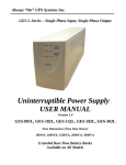
1
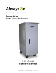
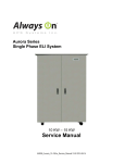
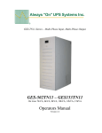
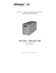
GES-TN31-Series – 3Phase Input, Single Phase Output
GES-103TN31, GES153TN31, GES203TN31
On Line: 10kVA, 15kVA, 20kVA
Operators Manual
Version 2.1
THIS PAGE IS INTENTIONALLY BLANK
Always “On” UPS Systems Inc.
Note
The instructions contained in this manual are not intended to cover all of the details or
variations in equipment, or to provide for every possible contingency to be met in connection
with installation, operation, or maintenance. Should further information be desired or should
particular problems arise which are not covered sufficiently for the purchaser’s purposes, the
matter should be referred directly to Always On UPS Systems Inc.
Any electrical or mechanical modifications to this equipment, without prior written consent of
Always On UPS Systems Inc, will void all warranties and may void UL/cUL listing.
Unauthorized modifications also can result in personal injury, death, or destruction or the
equipment.
Uninterruptible Power Supply
Please complete the Warranty Card supplied with this UPS and return it by mail to Always On
UPS Systems Inc. This activates the warranty.
If additional information or technical assistance is required call:
Always On UPS Systems Inc Sales and Technical Support Line
Toll free at 1 -877-259-2976 Ext. 451 or (250) 491-9777 Ext . 451 or Fax (250) 491-9775
Or E -mail at [email protected] or visit our web site at www.alwaysonups.com
Or write to
Always “On” UPS Systems Inc.
Bldg 1 – 150 Campion Road,
Kelowna, BC,
V1X 7S8,
Canada
Please complete the following information for your records and to remain within this equipment
manual.
Model Number:
Serial Number:
Date of Installation:
Inspected By:
i
Always “On” UPS Systems Inc.
THIS PAGE IS INTENTIONALLY BLANK
ii
Always “On” UPS Systems Inc.
IMPORTANT SAFETY INSTRUCTIONS
•
•
•
•
•
•
•
•
•
•
THIS MANUAL CONTAINS IMPORTANT INSTRUCTIONS THAT SHOULD BE
FOLLOWED DURING INSTALLATION AND MAINTENANCE OF THE UPS AND
BATTERIES.
THE UPS SYSTEM IS NOT INTENDED FOR EXTERNAL USE UNLESS
SPECIFICALLY DESIGNED FOR IT.
ALL SERVI CING MUST BE DONE BY QUALIFIED PERSONNEL. DO NOT
ATTEMPT TO SERVICE THIS EQUIPMENT YOURSELF.
OPENING OR
REMOVING COVERS WILL RISK EXPOSURE TO DANGEROUS VOLTAGES. DO
NOT LOCATE UPS IN AN AREA WHERE UNAUTORIZED PERSONNEL HAVE
ACCESS.
THE POWER SUPPLY FOR THIS UNIT MUST BE SINGLE PHASE RATED IN
ACCORDANCE WITH THE EQUIPMENT DATA PLATE. IT MUST BE SUITABLY
GROUNDED.
DO NOT STAND BEVERAGE CONTAINERS ON THE UNIT.
EXTERNAL LOUVRES AND OPENINGS IN THE CABINET ARE PROVIDED FOR
VENTILATION. TO ENSURE RELIABLE OPERATION OF THE PRODUCT AND
TO PROTECT FROM OVERHEATING, THESE OPENINGS MUST NOT BE
BLOCKED OR COVERED. OBJECTS MUST NEVER BE INSERTED INTO
VENTILATION HOLES OR OPENINGS.
THE POWER OUTLET ON THE UPS DISTRIBUTION PANEL WILL BE LIVE
WHEN THE UNIT’S POWER SWITCH IS ON, WHETHER OR NOT THE UNIT AC
SUPPLY IS PRESENT.
QUALIFIED PERSONNEL SHOULD BE CONSULTED WHEN:
1.
THE POWER CABLE HAS BEEN DAMAGED
2.
LIQUID HAS BEEN SPILLED INTO THE UNIT
3.
THE UNIT DOES NOT OPERATE NORMALLY EVEN THOUGH THE
OPERATING INSTRUCTIONS HAVE BEEN FOLLOWED
DO NOT PLACE MAGNETIC STORAGE MEDIA ON TOP OF THE UNIT, AS THIS
CAN RESULT IN DATA CORRUPTION.
THIS UPS WAS DESIGNED TO POWER ALL MODERN COMPUTER LOADS AND
ASSOCIATED PERIPHERAL DEVICES, SUCH AS MONITORS, MODEMS,
CARTRIDGE TAPE DRIVES, EXTERNAL FLOPPY DRIVES, ETC. DO NOT USE
IT FOR PURE INDUCTIVE OR CAPACITIVE LOADS. IT IS NOT RATED TO
POWER LIFE SUPPORT EQUIPMENT.
WARNING: ALL RECORDED MEDIA, SUCH AS DISKETTES, TAPES AND
CARTRIDGES, SHOULD BE KEPT A MINIMUM OF 60CM FROM THE UPS. THE
MAGNETIC FIELD CREATED BY OPERATION OF THE UPS MAY ERASE DATA
ON THOSE DEVICES.
WARNING: INSTALL THE ON-LINE UPS IN A WELL-VENTILATED AREA,
AWAY FROM FLAMMABLE LIQUIDS, GASES, OR EXPLOSIVES. DO NOT LET
THE UNIT COME INTO CONTACT WITH WATER. POTENTIALLY LETHAL
VOLTAGES EXIST WITHIN THIS UNIT AS LONG AS THE BATTERIES ARE
CONNECTED. DO NOT TOUCH ELECTRICAL CIRCUITS WHEN POWER IS
CONNECTED TO THE UPS. TURN THE UPS “OFF” AND DISCONNECT THE UNIT
FROM THE POWER SOURCE BEFORE REMOVING THE COVER PLATES. ALL
REPAIRS SHOULD BE PERFORMED BY A QUALIFIED SERVICE PERSONNEL.
READ THIS MANUAL CAREFULLY BEFORE INSTALLING OR USING THE UNIT.
FOLLOW ALL PROCEDURES, AS DESCRIBED, TO INSURE SAFE, RELIABLE
OPERATION OF THE UPS.
SAVE THESE INSTRUCTIONS
iii
Always “On” UPS Systems Inc.
MORE SAFETY INSTRUCTIONS
•
•
•
•
•
•
•
•
•
•
•
•
•
•
•
•
•
DO NOT USE THIS EQUIPMENT FOR ANY PURPOSE OTHER THAN THE
INTENDED USE.
EXAMINE THE PACKAGING CONTAINER FOR DAMAGE. NOTIFY THE
CARRIER IMMEDIATELY IF DAMAGE IS PRESENT.
DO NOT DISASSEMBLE THE UPS.
DO NOT OPERATE OR LOCATE NEAR WATER OR EXCESSIVE HUMIDITY.
DO NOT USE OTHER MANUFACTURERS ACCESSORIES. MAY CAUSE DAMAGE
OR UNSAFE CONDITIONS
KEEP LIQUID AND FOREIGN OBJECTS FROM GETTING INSIDE THE UPS.
DO NOT BLOCK AIR VENTS IN THE FRONT OF THE UPS OR AIR EXHAUSTS IN
THE BACK.
DO NOT PLACE OR OPERATE CLOSE TO GAS, HEATERS OR FIRE.
DO NOT LET POWER CORDS CONTACT HOT SURFACES
DO NOT PLUG APPLIANCES, SUCH AS HALF BRIDGE RECTIFIED LOADS, INTO
THE UPS.
USE CAUTION WHEN SERVICING BATTERIES. BATTERY ACID CAN CAUSE
BURNS TO SKIN AND EYES. IF ACID IS SPILLED ON SKIN OR IN EYES, FLUSH
ACID WITH FRESH WATER AND CONTACT A PHYSICIAN IMMEDIATELY.
DO NOT OPERATE IF THE UNIT IS LEAKING LIQUID OR IF A WHITE POWDERY
RESIDUE IS PRESENT.
BATTERIES MAY CONTAIN METALS AND OTHER CHEMICAL HAZARDOUS
WASTE. FOR PROPER DISPOSAL, CONSULT YOUR LOCAL STATE AND
FEDERAL EPA AND OTHER ENVIRONMENTAL LAWS AND REGULATIONS.
USE ONLY THE POWER SUPPLY CORD PROVIDED WITH THIS UNIT. THE
POWER CORD FOR UPS IS WIRED IN ACCORDANCE WITH NATIONAL
ELECTRICAL CODE (NEC) SPECIFICATIONS. BE SURE THAT THE WALL
OUTLET IS ALSO WIRED TO THESE SPECIFICATIONS.
THE UPS CONTAINS ITS OWN ENERGY SOURCE (BATTERY). THE OUTPUT
RECEPTACLES MAY BE LIVE EVEN WHEN THE UPS IS NOT CONNECTED TO
AN AC SUPPLY.
ONCE YOU HAVE CONNECTED THE BATTERY CONNECTORS, DO NOT
ATTEMPT TO LIFT THE CABINETS.
DO NOT CONNECT OR DISCONNECT BATTERY CABINETS WHILE THE UPS IS
OPERATING FROM BATTERY.
SYMBOLS
Protective grounding terminal; a terminal which must be connected to ground prior to
making any other connection to the equipment.
A terminal to which or from which an alternating (sine wave) current or voltage may be
applied or supplied.
A terminal to which or from which a direct current or voltage may be applied or supplied.
This symbol indicates the word “phase”.
May be used in lieu of the wording “caution, risk of electric shock” for any cautionary
marking.
iv
Always “On” UPS Systems Inc.
Table of Contents
1.
INTRODUCTION ...........................................................................................................................1
2.
PRODUCT DESCRIPTION ........................................................................................................3
2.1. BLOCK D IAGRAM OF THE TN31.......................................................................................................3
2.2. THEORY OF O PERATION .....................................................................................................................4
2.3. D ESCRIPTION OF S IGNIFICANT B LOCKS ..........................................................................................4
3.
HANDLING.......................................................................................................................................5
3.1. D ELIVERY .............................................................................................................................................5
3.2. INITIAL INSPECTION ............................................................................................................................5
3.3. STORAGE...............................................................................................................................................5
4.
INSTALLATION ............................................................................................................................7
4.1. L OCATION.............................................................................................................................................7
4.2. E LECTRICAL CONSIDERATIONS ........................................................................................................9
4.3. D IAGRAM OF FRONT COVER O PEN F OR 20 KVA .......................................................................10
4.4. D IAGRAM OF REAR VIEW FOR 10 K VA & 15 K VA ..................................................................11
4.5. INPUT , O UTPUT AND E XTERNAL BATTERY CONNECTION ........................................................12
5.
START-UP/SHUTDOWN ..........................................................................................................13
5.1. TURN O N P ROCEDURE: ....................................................................................................................13
5.2. TURN O FF / SHUTDOWN P ROCEDURE: ..........................................................................................13
6.
FRONT CONTROL PANEL ....................................................................................................15
6.1. CONTROL PANEL OPERATION ............................................................................................15
6.2. CONTROL P ANEL INDICATION TRUTH T ABLE .............................................................................16
7.
AUDIBLE ALARM......................................................................................................................17
7.1. BACKUP MODE ...................................................................................................................................17
7.2. L OW BATTERY ...................................................................................................................................17
7.3. FAULT ..................................................................................................................................................17
8.
MAINTENANCE BYPASS O PERATION ..........................................................................19
8.1. TO PUT THE UPS INTO “ MANUAL BYPASS ” MODE:...................................................................19
8.2. TO RESTORE THE UPS TO NORMAL OPERATION: ........................................................................20
9.
BATTERY MAINTENANCE...................................................................................................21
10.
ENVIRONMENTAL PROTECTION ...................................................................................21
11.
BATTERY REPLACEMENT ..................................................................................................23
12.
STANDARD SOFTWARE ........................................................................................................25
12.1. A BOUT THE SOFTWARE ............................................................................................................25
12.2. INSTALLATION OF THE S OFTWARE ........................................................................................25
12.3. RS-232 I NTERFACE ..................................................................................................................26
12.4. D RY CONTACT...........................................................................................................................27
13.
OPTIONAL EXTRAS .................................................................................................................29
13.1. INSTALLATION P ROCEDURE FOR (OPTIONAL) E XTENDED BATTERY CABINETS .........29
13.2. AS-400 AND D RY CONTACT (OPTIONAL) ...........................................................................31
13.3. SNMP (W EB A CCESSIBLE MONITORING) A DAPTER ........................................................32
14.
TROUBLESHOOTING..............................................................................................................33
15.
TECHNICAL DATA ....................................................................................................................34
16.
CONTACT INFORMATION ...................................................................................................37
16.1. A DDITIONAL P URCHASES OR U PGRADES .............................................................................37
16.2. QA / W ARRANTY Q UESTIONS ................................................................................................37
16.3. SOFTWARE Q UESTIONS ............................................................................................................37
v
Always “On” UPS Systems Inc.
THIS PAGE IS INTENTIONALLY BLANK
vi
Always “On” UPS Systems Inc.
1.
Introduction
Congratulations on your choice of the Always “On” TN31 Series On-Line Uninterruptible
Power System (UPS). The TN31 Series features the very latest, top of the line, microprocessor
technology and IGBT transistors for clean, highly regulated, PWM (Pulse Width Modulated)
power. Also included within our high quality engineering is an output isolation transformer to
provide the final touch to complete power conditioning and noise attenuation, even during
bypass operation.
Powerful standard features such as the ability to operate on wide input voltages allow use with
generators, offers reduced discharges of the batteries and higher reliability of the UPS.
For ease of use, the TN 31 Series utilizes a simple to read LED display to indicate load
percentage, battery capacity and the mode of operation at a glance. The TN31 series micro
processing technology operates self-diagnostic algorithms and provides a fault indicator to aid
in troubleshooting. The On and Off/Bypass selection buttons are conveniently located with the
display.
The TN31 Series incorporates an interface port for communications between the UPS and a
LAN server or other computer system with various operating systems installed. This port
provides detailed operating information including voltages, currents, and alarm status to the
host system when used in conjunction with the shutdown software. Also available are the
optional SNMP Adapter to permit remote monitoring and n otification of UPS conditions via a
network or the Internet, and an AS-400 interface to allow for relay communications in PLC or
contact environments.
1.1
Modes of Operation
The TN Series UPS is designed to operate as a continuously on-line dual conversion
system in the following modes:
Normal - The critical AC load is continuously supplied by the UPS Inverter. The
input Rectifier derives power from a utility AC source and supplies power to the
Inverter while simultaneously float-charging the batteries.
Emergency - Upon failure of AC utility, the Inverter obtains power from the batteries
without interruption. There are no interruptions in power to the critical load upon
failure or restoration of the AC utility source.
Recharge - Upon restoration of AC utility, the Rectifier will automatically restart and
supply DC power to the inverter and battery charger.
Automatic Restart - Upon restoration of AC utility, after an extended utility and
complete battery discharge, the UPS will automatically restart and resume supplying
power to the critical load. Also the battery charger will automatically start and
recharge the batteries. [This feature is enabled in the factory and is capable of being
disabled (consult factory).]
Static Bypass - The bypass will provide an alternate path for power to the critical
load that is capable of operating in the following manner:
Automatic - In the event of the inverter overload capacity be exceeded or
should an internal failure occur, the UPS will perform an automatic transfer of
the critical AC load from the inverter to the bypass source.
Manual - Should the UPS need to be taken out of service for limited
maintenance or repair, manual activation of the bypass will cause an
immediate transfer of the critical AC load from the inverter to the bypass
source. The input rectifier, inverter, and battery charging operations will be
inhibited until the user transfers the UPS back to normal operation.
Maintenance Bypass – All TN Series units include provisions to allow for
maintenance of the unit or replacement of batteries without interruption of power to
the load. This will be done with the manually operated bypass switch included.
1
Always “On” UPS Systems Inc.
THIS PAGE IS INTENTIONALLY BLANK
2
Always “On” UPS Systems Inc.
2.
Product Description
2.1. Block Diagram of the TN31
Figure 2.1.1
Block Diagram of TN Series
3
Always “On” UPS Systems Inc.
2.2. Theory of Operation
The UPS (Uninterruptible Power Supply) is designed for installation between the
utility (commercial supplied power) and your load. It is designed to protect your load
from experiencing any power fluctuations like blackouts, brownouts and over-voltage
conditions. The UPS supplies sufficient amounts of steady, constant AC power
during these power fluctuations. Thus, you are empowered to shut down your load
properly, preventing possible damage to both hardware and software.
2.3. Description of Significant Blocks
Input Breaker:Prevents the main distribution panel breaker from tripping when a
UPS fault or over-current condition occurs.
Surge Protection: Provides protection to UPS and equipment from power surges
such as lighting and phase-to-phase faults.
Input EMI/RFI Filter: This filter attenuates the electrical noise associated with the
polluted utility power to the UPS or noise (THD) generated by the UPS.
Rectifier : Incoming AC power is converted to DC by the rectifier. The rectifier
supplies DC power to the i nverter.
Internal Charger: Charges the included battery pack. A quick charge is
approximately 6hrs duration and a slow charge is approximately 10 hrs duration.
Float operation is also included.
Batteries: Sizes will vary in series and series-parallel configurations. Batteries are
sealed lead-acid valve regulated gel cells. Extra External Battery Cabinets may be
added in parallel to provide extra runtime.
Inverter: The inverter is the solid-state equipment and controls used to convert DC
from the rectifier or batteries to AC power for the load. The inverter will produce 50
or 60Hz (auto-selectable) using Insulated Gate Bipolar Transistors (IGBT’s) that
switch at ~ 18kHz. This is above the audible frequency range and does not generate
low frequency magnetic components. The inverter uses pulse width modulation
(PWM) to generate and regulate the AC output with a very small tolerance (±2%).
CPU/Control Panel/Communications : The CPU controller monitors and maintains
all systems within the UPS while permi tting communication between the UPS, user
and peripheral devices.
Static Bypass: A static transfer switch and bypass circuit is integrated into the UPS.
This provides an automatic bypass of the UPS if there is a problem. The CPU
controller controls the automatic bypass by sensing the status of the inverter logic
signals, operating and alarm conditions. This control circuit will provide an
uninterrupted transfer of the load to a normal input source (or alternate bypass
source). Transfers are made when an overload or malfunction occurs within the UPS,
without exceeding the transient limits specified herein.
Maintenance Bypass: Allows for power wrap-around from input directly to output,
while still utilizing the output isolation transformer. This provides a convenient way
to permit maintenance of the UPS system.
Transformer: An output isolation transformer is included. The output transformer is
factory installed inside the UPS module cabinet. The transformer features tap
selection to serve any input and o utput voltage configurations in the UPS module.
4
Always “On” UPS Systems Inc.
3.
Handling
3.1. Delivery
Check condition of equipment on delivery. Contact the carrier and supplier
immediately if the packaging or unit is damaged.
3.2. Initial Inspection
Unpack the UPS carefully, notice the packing method, and retain the box and packing
material. If you must return the UPS at any time, you must repack it the way it was
originally shipped. Visually inspect the UPS for damage that may have occurred
during shipment. If there is damage, or anything is missing, contact the dealer from
whom you purchased the unit, and save the packaging for future shipment. When the
unit has passed the initial inspection, record the Installation date on the back panel of
the unit and in the space provided towards the front of this manual.
Included with UPS System:
1. User manual
2. Communication cable
3. Software package
4. AS400 cable (when optional AS400 included)
3.3. Storage
1. If the on-line UPS is to be stored prior to installation, it should be placed in a dry,
well-ventilated area where it will not be exposed to dirt, moisture or other
contaminants.
2. Extreme storage temperatures are:
i. -30ºC to +60ºC without battery
ii. -20ºC to +45ºC with battery for a short period
3. Maximum storage period for battery is 6 months at 20ºC or 3 months at 30ºC.
IMPORTANT:
1.
When the UPS and/or battery banks are to be stored for longer
than 3 months, it is recommended the batteries are recharged
every 3 months.
2.
Do not stack these units.
3.
Once the unit is taken out of storage for a long period, it is
recommended that the batteries be charged before putting the
UPS into full service. Refer to start up procedure 5.1 and follow
the steps for turning the UPS on. Leave the unit running for at
least 8 hours, preferably unloaded, so that the batteries may
charge.
5
Always “On” UPS Systems Inc.
THIS PAGE IS INTENTIONALLY BLANK
6
Always “On” UPS Systems Inc.
4.
Installation
4.1. Location
The TN31 Series UPS is intended for installation in a controlled indoor environment
where temperature and humidity levels are maintained, free of conductive
contaminants with unrestricted airflow. Ambient temperature must not exceed 40ºC
(104ºF).
IMPORTANT: Maximum battery life is obtained by placing the battery in a room at
an ambient temperature of 15ºC to 25ºC. Battery life decreases by half for every
10ºC above 25ºC.
The unit is fitted with castor wheels for moving it over a short distance.
Figure 4.1.1
Front View 20 kVA
7
Always “On” UPS Systems Inc.
Figure 4.1.2
Front View 10 kVA & 15 kVA
8
Always “On” UPS Systems Inc.
Air vents are located on the rear and sides of the UPS system. Do not position the
UPS in an enclosed area with restricted airflow. Allow a minimum of 100mm (4
inches) around the UPS, with a minimum of 300mm (12 inches) at the rear for easy
operator access to the connections and the rear panel mounted
input/output/battery/maintenance breakers. (Figure 4.1.2)
Maintenance/Servicing of the TN31 Series requires access to all side of the UPS
system and battery banks. Provide the necessary free space and flexible wiring to
allow complete access to the UPS.
Figure 4.1.3
Top View
4.2. Electrical Considerations
WARNING: The UPS shall be installed by a qualified technician and wired
in accordance with local and national electrical codes.
The following information is for recommendation only.
Input
The commercial supply input cable shall be connected to the UPS via a
dedicated 3-pole circuit breaker rated for operation and protection of the
UPS branch circuit. The breaker is to be mounted within two meters (six
feet) of the UPS and be readily accessible to the operator.
Output
Provide adequately sized cabling, distribution panel and circuit breakers to
supply the critical loads with the power available.
Optional Battery Bank AC Supply
If battery banks have been purchased, ensure a separate double pole breaker
is available to connect to the battery bank chargers. One 15A double pole
breaker will power three battery bank chargers.
9
Always “On” UPS Systems Inc.
4.3. Diagram of Front Cover Open For 20 kVA
The 20 kVA unit has the terminations and switches behind the front door.
Figure 4.3.1
Front View 20 kVA With Door Open
10
Always “On” UPS Systems Inc.
4.4. Diagram of Rear View For 10 kVA & 15 kVA
Figure 4.4.1
Rear view of the TN31 10 kVA & 15 kVA
11
Always “On” UPS Systems Inc.
4.5. Input, Output and External Battery
Connection
The UPS is supplied with an input, output and battery terminal block assembly
located on the rear of the UPS system.
The cable sizes and distribution methods used during installation are subject to the
local and national electrical codes of practice, therefore are not detailed here.
Permanent wiring must be routed to the terminal block using appropriate materials as
required by local and national codes.
External battery bank connections are described later in this manual.
Ensure UPS is provided with an adequate ground (earth).
Figure 4.5.1
Rear view of the TN31 10 kVA & 15 kVA
12
Always “On” UPS Systems Inc.
5.
Start-up/Shutdown
Once the UPS is installed, make sure it is located on a sturdy, well-ventilated surface, and that
the exhaust fans and ventilation grills are not obstructed.
5.1. Turn On From Shutdown Procedure:
1. Switch the “BATTERY” Breaker to the “ON” position.
(Wait 10 seconds)
2. Switch the “INPUT” Breaker to the “ON” position.
Control Panel LED Display will light up, fans will start, etc.
(Wait 25 seconds) Refer to Figure 6.1.1.
“INVERTER” indicator on the mimic diagram will light up.
The “BYPASS” indicator will turn off after 25 seconds.
The UPS inverter will automatically produce a voltage at the output once the
bypass indicator turns off.
WARNING: If there is utility voltage present at the input of the UPS during
startup, there will be a voltage at the output immediately after the input
breaker is turned on. This is because the unit is temporarily in “BYPASS”
mode for 25 seconds prior to the UPS inverter taking over.
5.2. Turn Off / Shutdown Procedure:
1. Press and hold the Front Panel “OFF” button for one (1) second.
The UPS is now in Bypass Mode and the UPS inverter is shut down. The
“BYPASS” indicator will turn on. (The unit can be turned on again from this
point by pressing and holding the “ON” button for one (1) second).
WARNING: If there is utility voltage present at the input of the UPS and the
input breaker is on, there will still be a voltage at the output after the “OFF”
switch is pushed. This is because the unit is in “BYPASS” mode.
2. Switch the “INPUT” Breaker to the “OFF” position.
The UPS will do a Power Down sequence.
Front Panel Display LEDs will not be on.
Fans will stop.
(Wait 10 seconds)
3. Switch the “BATTERY” Breaker to the “OFF” position.
4. The UPS is now fully shut down.
13
Always “On” UPS Systems Inc.
THIS PAGE IS INTENTIONALLY BLANK
14
Always “On” UPS Systems Inc.
6.
Front Control Panel
6.1. CONTROL PANEL OPERATION
Figure 6.1.1
Front Control Panel
FRONT CONTROL PANEL FUNCTIONS
FUNCTION
PROPERTIES
A
LINE (UTILITY ON)
B
INVERTER ON
C
BYPASS
MIMIC DIAGRAM: INDICATES UTILITY IS ON
MIMIC DIAGRAM: INDICATES INVERTER IS
OPERATING
MIMIC DIAGRAM: INDICATES UPS IS IN BYPASS
MODE
D
FAULT
INDICATES SELF DIAGNOSTICS HAS FOUND A
PROBLEM IN THE UPS OR BATTERIES
E
LOAD LEVEL
BAR GRAPH INDICATION OF LOAD LEVEL FROM
0 TO 150%
F
BATTERY CHARGE
LEVEL
BAR GRAPH INDICATION OF BATTERY CHARGE
LEVEL FROM 0 TO 100%
G
UPS ON BUTTON
H
UPS OFF BUTTON/
BYPASS MODE
ON BUTTON TO TURN UPS ON TO DUAL
CONVERSION OR INVERTER MODE
TO TURN UPS OFF DUAL CONVERSION OR
INVERTER MODE, PUTS INTO BYPASS MODE
Figure 6.1.2
Front Control Panel Functions List
15
Always “On” UPS Systems Inc.
6.2. Control Panel Indication Truth Table
LED STATUS
LINE
(A)
INVERTER
(B)
BYPASS
(C)
FAULT
(D)
ALARM
STATUS
ON
ON
OFF
OFF
NO ALARM
NORMAL
OFF
ON
OFF
OFF
ON
OFF
ON
OFF
ON
OFF
ON
OFF
CONTINUOUS
ALARM
OVERLOAD
OFF
ON
OFF
OFF
RAPID
BEEPING
EVERY 0.5
SECONDS
BATTERY LOW
ON
OFF
OFF
OFF
CONTINUOUS
BEEPING
BATTERY DEAD
& UTILITY
FAILURE
ON
ON
DELAYED
OFF
DELAYED
OFF
CONTINUOUS
ALARM
MAIN POWER
SWITCH ON.
ON
OFF
ON
ON
CONTINUOUS
BEEPING
INVERTER
FAULT OR
OVERLOAD
ON
ON
OFF
OFF
EVERY 4
SECONDS
UPS FAULT
BEEP EVERY 4
SECONDS
Figure 6.2.1
Control Panel & Alarm Indication Truth Table
16
UTILITY POWER
FAILURE/
MAIN POWER
SWITCH OFF.
Always “On” UPS Systems Inc.
7.
Audible Alarm
Please refer to Control Panel Indication Truth Table for Alarm Status and Indication.
7.1. Backup mode
The UPS will beep once every four (4) seconds when the unit is in back-up mode.
(beep - - - beep - - - beep) [Slow beep]
NOTE: The UPS incorporates a mute function. When the UPS is beeping
press the “ON” button on the front display to mute. Press the “ON” button
again to reactivate.
7.2. Low Battery
The UPS will beep at 2 Hz or every 0.5seconds when the batteries are almost
depleted.
(beep - beep - beep) [Fast beep]
NOTE: When a low battery condition occurs, the Audible Alarm cannot be
reset and silenced.
7.3. Fault
The UPS will sound a continuous beep and the fault light indicator will illuminate.
(beeeeep) [Continuous beep]
7.4. Silencing the Audible Alarm
To silence the audible alarm in battery backup mode, push the alarm-reset button,
located on the front panel.
17
Always “On” UPS Systems Inc.
THIS PAGE IS INTENTIONALLY BLANK
18
Always “On” UPS Systems Inc.
8.
Maintenance Bypass Operation
(Qualified Technicians or Service Personnel Only)
The purpose of the Maintenance Bypass Switch and Inverter Switch is to provide a “Manual
Bypass” function. This function allows electrical removal of the UPS from the load. Thus
maintenance may be perfo rmed on the UPS without disturbing the load. This is an important
feature for mission critical load applications. On the 10 & 15 kVA UPS systems, the switch is
located under a removable cover plate to prevent accidental operation. On the 20 kVA system,
the switch is located behind the front door.
Figure 8.1
20 kVA Manual Bypass Switch Location
Figure 8.2
10 kVA & 15 kVA Manual Bypass
Switch Location
During normal operation the Inverter Switch is in the “ON” position, and the Maintenance
Switch is in the “OFF” position.
WARNING: Utility power will be fed directly into the inverter output if
both the Inverter and the Maintenance Switches are “ON” during normal
operation. This may damage the UPS.
8.1. To put the UPS into “Manual Bypass” mode:
(a)
P u s h “ OFF” button (green one on front display panel) and the BYPASS LED
will light if using manual bypass mode.
(b) Open the metal cover of the MANUAL BYPASS SWITCH CB3. Switch on the
MANUAL BYPASS SWITCH CB3.
(c) Switch off CB2
(d) Turn off the input circuit breaker.
The UPS electronics are now shut down and you may begin maintenance work.
19
Always “On” UPS Systems Inc.
8.2. To restore the UPS to normal operation:
(a) Turn on the input circuit breaker.
(b) Switch on CB1 and push the “OFF” button on the control panel. The BYPASS
indicator on the control panel should light up.
(c) Switch on CB2.
(d) Switch off MANUAL BYPASS SWITCH CB3.
(e) Push “ON” button on the control panel. The INVERTER indicator on the
control panel should light. The BYPASS indicator turns off after a delay of 25
seconds and the UPS inverter shall be supplying power to the load.
(f) Replace the metal cover over the MANUAL BYPASS SWITCH CB3.
20
Always “On” UPS Systems Inc.
9.
Battery Maintenance
•
•
•
•
•
•
On initial start-up it is recommended the batteries have a minimum of eight (8) hours of
charging to ensure proper operation.
During normal operation of the UPS, the charge level of the batteries will be maintained
automatically.
The typical recharge time to 90% from 0% charge level is 6 -8 hours
Under normal operating conditions, the supplied batteries are expected to last
approximately five (5) years, o r 200 discharges, from date of receipt.
Refer to the purchase date you recorded in this manual if you suspect that the batteries
have been exhausted.
If the UPS is to remain in storage for an extended period of time, it is strongly
recommended that the UPS be powered up every three (3) months for a period of twentyfour (24) hours to recharge the batteries and prevent premature failure.
10. Environmental Protection
The UPS incorporates sealed maintenance free lead-acid batteries. When replacing the batteries,
the defective batteries must be disposed of carefully to prevent any risk of environmental
pollution by the harmful products they contain (lead and acid). Please refer to local and regional
environmental codes when disposing of the batteries.
21
Always “On” UPS Systems Inc.
THIS PAGE IS INTENTIONALLY BLANK
22
Always “On” UPS Systems Inc.
11. Battery Replacement
When replacing batteries, use the same number and following types of batteries:
UPS Rating
10kVA
15kVA
20kVA
Number of Batteries
16
16
30
Type of Batteries
12VDC – 7Ah
12VDC – 26Ah
12VDC – 26Ah
Combined Voltage
192VDC
192VDC
360VDC
Table 11.1
Battery Types and Quantities
WARNING: Potentially lethal voltage exists within this unit as long as
the battery supply is connected.
During any service work, the battery should be disconnected from the
UPS by turning off the battery breaker. The battery cabinet assembly
is heavy. Use suitable lifting equipment.
WARNING: Servicing of the batteries should be performed or
supervised by personnel knowledgeable of batteries and the
required precautions.
•
Keep unauthorized personnel away from the batteries.
•
Do not dispose of batteries in a fire. They may explode.
•
Do not open or mutilate the battery or batteries. Released
electrolyte is harmful to the skin and eyes. It may be toxic.
•
A battery can present a risk of electrical shock and high
short circuit current. The following precautions should be
observed when working on batteries:
o
o
o
o
o
o
o
Remove watches, rings, and other metal objects.
Use tools with insulated handles.
Wear rubber gloves and boots.
Do not lay tools or metal parts on top of
batteries.
Disconnect charging source prior to connecting
or disconnecting battery terminals.
Determine whether the battery is grounded. If
grounded, remove the source of the ground
connection.
Contact with any part of a grounded ba ttery can
result in electrical shock. The likelihood of such
a shock is reduced if grounding is removed
during installation and maintenance. This is
applicable to a UPS with a remote battery
supply not having a grounded supply circuit.
23
Always “On” UPS Systems Inc.
THIS PAGE IS INTENTIONALLY BLANK
24
Always “On” UPS Systems Inc.
12. Standard Software
12.1. About the Software
UPSilon 2000 offers powerful features such as the ability to monitor local UPS's, as
well as remote units by TCP/IP, from your central location. Also UPSilon 2000 can
notify you of any problems automatically by sending email or dialing your pager
through a modem when an event occurs such as a power outage. UPSilon 2000 can
also broadcast messages to remote computers and even send them commands to
shutdown with the included software package ClientMate.
The UPSilon 2000 GUI is a real time graphical display of UPS status including
input/output voltage, frequency, load, temperature, and capacity. It also has a datalogging feature.
For battery management, UPSilon 2000 will shutdown the system in a safe fa shion
before the batteries run out.
NOTE: The UPS can run without the software.
12.2. Installation of the Software
1.
2.
3.
Install Software package included with the UPS and follow software instruction
included with CD.
Connect the UPS to the computer via the RS-232 cable included with the software
package.
Start software.
NOTE: Use the connecting cord supplied by the manufacturer or the
monitoring software will not work.
Follow the “read me” file on the disk to run the setup.
25
Always “On” UPS Systems Inc.
12.3. RS-232 Interface
A 9-pin female SUB-D connector is located on the UPS rear panel to provide a
communications link between the UPS and the computer. The software package and
interface allows the user to monitor the operating status of the UPS system.
UPS Port
Computer Port
Pin
Assignment
Pin
Asssignment
6
Transmit Data (TXD)
2
Receive Data (RXD)
7
Receive Data (RXD)
3
Transmit Data (TXD)
9
Signal Ground (GND)
5
Signal Ground (GND)
Table 12.3.1
Battery Types and Quantities
Figure 12.3.1
Pin Configuration of RS-232 port on the UPS
26
Always “On” UPS Systems Inc.
12.4. Dry Contact
Dry Contact outputs and Photo Diode-Coupled inputs are provided through the RS232 port located at the back of the UPS. Each output contact provides status
information of the UPS operation.
These statuses enable the UPS to notify an unattended computer or automation device
being supported by the UPS of a power anomaly. The connected device may then be
programmed to recognize these signals and initiate a shutdown sequence.
The UPS reads the input signals through a photo-coupled diode-transistor pair, so
your control equipment remains electrically isolated.
Maximum conduction levels are 40VDC at 40mA.
Pin
2
4
5
Function
Power Fail
Reference Ground
Battery Low
6
Remote Shutdown
of UPS
7
Reference Ground
Operation/Explanation
Normally Open (N/O)
Reference GND for Pins 2, 5
Normally Open (N/O)
Maintain pulse of +5VDC to
+12VDC for 500ms to
shutdown the UPS.
Available When System is in
Battery Mode.
Reference GND for Pin 6
Table 12.4.1
Pin Assignment
Figure 12.4.1
Photo-Coupled Transistor
27
I/O
OUTPUT
OUTPUT
OUTPUT
INPUT
INPUT
Always “On” UPS Systems Inc.
THIS PAGE IS INTENTIONALLY BLANK
28
Always “On” UPS Systems Inc.
13. Optional Extras
13.1. Installation Procedure for (Optional) Extended
Battery Cabinets
WARNING: It is important to follow the correct procedures for connecting
the battery packs. If the procedures are not followed properly, it will increase
the chance of electrical shock, damage or death. Follow the procedure to
avoid any possible danger.
WARNING: Observe the appropriate federal and local electrical regulations
at all times. Using cables of improper size may dama ge your equipment and
cause fire hazards. Also, make sure the UPS and the load equipment are
grounded to a common point to prevent ground current loops.
1)
Battery Cabinet(s) should be installed as close as possible to the UPS system.
The cable from the Battery Cabinet to the UPS should be as short as possible.
WARNING: Choose the correct battery pack voltage according to the UPS
rated capacity. Do not connect too few or too many batteries, as this could
cause electrical shock, damage or death.
2)
The DC Voltage of the Battery Cabinet must be the same as the DC Voltage of
the UPS system. Battery Bank Voltage is 240VDC nominal.
3)
Before connecting the Battery Cabinet to the UPS:
i) You Must Power down the UPS and remove input AC supply.
ii) Battery Breaker MUST BE in the “Off” position on the UPS system and
Battery Bank.
The battery cable that is supplied shall be hardwired to the Battery Cabinet and
the UPS without connectors.
4)
WARNING: Ensure correct battery bank voltage and polarity before
connecting. Ensure UPS is “OFF” and battery breakers are “OFF”. Do not
connect the wires to the UPS first, electrical shock will occur.
5)
If multiple battery banks have been purchased connect all batteries banks
together in a parallel fashion. Refer to figure 13.1.1 for a parallel connection.
Ensure batteries are connected with the proper polarities before connecting the
battery cable to the UPS. It is also recommended to test the cable voltage with a
Digital Voltmeter and compare with the battery voltage in Table 11.1 before
connecting the batteries to the UPS.
29
Always “On” UPS Systems Inc.
6)
Connect the battery leads to the UPS terminal block with the proper polarities.
The positive battery cable connects to B+ and the negative battery cable
connects to B-
7)
The minimum tightening torque shall be no less than 35 ft lb/in.
8)
Additional Battery Cabinets for the TN31 series UPS require a 208VAC to
240VAC two-wire supply to power the additional charger that is provided with
the Battery Cabinet. Refer to Figure 13.1.1. The cable is not supplied for the
additional charger.
Start-up Procedure
1) Install the UPS system and Battery Cabinets(s) as per recommendations in
above procedure.
2) Once all connections are secure, turn all the Battery Breaker(s) “On”,
starting from farthest away from the UPS.
3) Perform the Turn On / Start-up Procedure for the UPS (Section 5.1).
Figure 13.1.1
Battery Bank and UPS Connections
30
Always “On” UPS Systems Inc.
13.2. AS-400 and Dry Contact (Optional)
An AS-400 25-Pin Connector is located on the rear panel of the UPS. This provides status
information through relay contacts and control by photo-coupled inputs.
Input Signal Pin Assignment:
Pins
Function
Explanation
Remote
24 & 25
Emergency
Shutdown
22 & 23
Remote Back-Up
Mode Shutdown
Output Signal Pin
Assignment:
Pins
UPS shuts down immediately when these 2 pins are
connected together.
UPS shuts down after a 40 second delay if VPin22 >
VPin23 by 5 to 12 VDC.
Function
1, 2 &3
Fault
4, 5 & 6
On Battery
7&8
Battery Low
9 & 10
On Bypass
11 & 12
On Inverter
Dry Contact Capacity:
Total maximum power rating is
30W
Maximum voltage rating is
250VAC
Maximum current rating is 3A
Optional:
Instrumentation Terminal Strip
Allow for easy connection of
wires if 25pin connector is not
available
Table 13.2.1
Pin Assignments
Figure 3.2.1
Line Drawing of AS-400 Communications Interface
Output Truth Table
State
Pin 1, 2
Pin
2,3
Closed
Open
Closed
Closed
Pin
4,5
Open
*1
Closed
Closed
Pin 5,6
Normal
Open
Closed
Fault
Closed
*1
On Battery
Open
Open
Battery
Open
Open
Low
On Bypass
*1
*1
*1
*1
On Inverter
Open
Closed
*1
*1
*1 = Inactive. State may be “open” or “closed” condition
Table 13.2.2
Output Truth Table
31
Pin 7,8
Open
*1
*1
Closed
Pin
9,10
Open
Closed
Open
Open
Pin
11,12
Closed
Open
Closed
Closed
*1
*1
Closed
Open
Open
Closed
Always “On” UPS Systems Inc.
13.3. SNMP (Web Accessible Monitoring) Adapter
The Always “On” Simple Network Management Protocol (SNMP) adapter is a webbased management product that uses multiple, open standards such as Telnet, HTTP,
and SNMP to provide full management of supported devices.
The SNMP Adapter is designed to connect directly to the network and allow for
network broadcasting of UPS conditions. Also, the SNMP Adapter empowers you to
have remote access to the UPS system to monitor parameters and displays.
For set-up instructions view the READ ME fi le provided with the set-up disk.
32
Always “On” UPS Systems Inc.
14. TROUBLESHOOTING
NOTE: Please check the following fundamental items if the UPS does not
function, before calling your authorized service center:
1.
Is the UPS connected to the power source?
2.
Is the input voltage and frequency within operating
parameters?
NOTE: When you contact Always On for service, please provide the
following information:
1.
UPS model name and serial number.
2.
Date the problem occurred.
3.
Complete description of the problem.
Table 14.1 is a troubleshooting chart for diagnosing abnormal and unusual situations. It includes
some possible problems and solutions occurring under daily operation.
TROUBLESHOOTING CHART
Problem
UPS will not operate,
or no lights or warning
sounds appear after
pressing On/Off
switches.
Possible Reasons
Input power source failure
Breaker switch on rear panel has been
opened
Time of pressing “On” button is too
short
Output short circuit or UPS overload
Indicates no utility and
warns every several
seconds
Fault light ON and
buzzer keeps beeping
Buzzer keeps beeping
No power source input
Utility indicating light
is flashing
Voltage of utility is exceeding UPS
input range
Battery backup time is
too short
UPS Input Breaker switch has opened
UPS has failed
Overload
Batteries have not been charged; UPS
overload; Batteries are aged and
cannot be charged fully
The charger has failed
The battery light is
flashing when utility is
supplying power to the
UPS
Battery voltage is too low or batteries
have not been connected
Table 14.1
Troubleshooting Chart
33
Solutions
Check power source
Press breaker switch to “On”
position
Press “On” button longer than 1
second
Turn off UPS, remove all load to
test for internal short circuit.
Press “On” button longer than 1
second
Check power source input
Turn breaker switch to the “On”
position
Contact dealer or service center
for help
Remove some of the load
Save digital data and shutdown.
Refer to the application program
to ensure utility is not within UPS
range
Keep UPS “On” for over 8 hours
to recharge the batteries. Check
the load and remove any noncritical equipment
Contact dealer or service center
for help
Check that UPS batteries are well
connected. Replace any damaged
battery packs immediately.
Always “On” UPS Systems Inc.
THIS PAGE IS INTENTIONALLY BLANK
34
Always “On” UPS Systems Inc.
15. TECHNICAL DATA
Standard Models (Isolation XFM Included)
TN31 SERIES
MODEL NO.
CAPACITY
INPUT
GES-103TN11
GES-153TN11
GES-203TN11
10kVA/8.0kW
15kVA/12kW
20kVA/16kW
PHASE / FREQUENCY
RATED VOLTAGE
(Nominal)
VOLTAGE RANGE
3-Ø (4 Wire +GND)
VOLTAGE / PHASE
120, 120/208, 120/240, 110/220VAC (3 WIRE + G)
170 - 276VAC
VOLTAGE REGULATION
OUTPUT
± 2%
TOTAL CURRENT
50A
62.5A
FREQUENCY ACCURACY
THD
50Hz / 60Hz ± 0.5%
< 3% LINEAR LOAD; < 5% RECTIFIED LOAD
0.7
SLEW RA TE
TRANSIENT RESPONSE
1Hz / SECOND
± 4% (100% LOAD CHANGE)
OVERLOAD CAPACITY
105% - 150% FOR 20 SECONDS
3:1
> 85%
TRANSFER TIME
0ms
OUTLETS
HARD -WIRED
BATTERY TYPE
VOLTAGE
RECHARGE TIME
CHARGING VOLTAGE
BACKUP POWER FULL LOAD
TIME
HALF LOAD
SEALED LEAD ACID - MAINTENANCE FREE
192VDC
5 - 8 HOURS;
210VDC
10 MIN.
8 MIN.
25 MIN.
20 MIN.
18 MIN.
AVAILABLE - CONSULT BATTERY BANKS
OUTPUT SHORT
YES
COMMON & NORMAL MODE NOISE SUPPRESSION
I/O SPIKE & TRANSIENT
PROTECTION
YES
SAFETY
APPROVAL
RS 232 / DRY CONTACT / (OPTIONAL SNMP OR AS400)
DISPLAY
AUDIBLE ALARMS
ENVIRONMENT
YES
ABNORMAL VOLTAGE
I/O NOISE PROTECTION
COMMUNICATION
INTERFACE
LED INDICATOR STATUS PANEL
ON BATTERY, LOW BATTERY, OVERLOAD, FAULT
OPERATING
TEMPERATURE
0-40°C
HUMIDITY
AUDIBLE NOISE
0% - 90% (NON-CONDENSING)
≥ 55 dBA AT 1 METER FROM UNIT
SAFETY
UL1778, CSA C22.2
EMI / RFI
FCC CLASS A
SURGE / TRANSIENT
PHYSICAL DATA
192VDC
360VDC
RECOVERY = 90%, TYPICAL
210VDC
410VDC
10 MIN.
EXTENDED RUN
TIME
PROTECTION
83.3A
LOAD POWER FACTOR
CREST FACTOR
EFFICIENCY (AC-AC)
BATTERY
50/60Hz
208VAC
IEEE C62.41 CAT.A
WxDxH in mm
340x640x980
340x760x1160
340x760x1160
WEIGHT in kg
250
255
265
35
Always “On” UPS Systems Inc.
THIS PAGE IS INTENTIONALLY BLANK
36
Always “On” UPS Systems Inc.
16. CONTACT INFORMATION
16.1. Additional Purchases or Upgrades
Always “On” UPS Systems Inc.
Bldg 1 – 150 Campion Road,
Kelowna, BC, Canada, V1X 7S8
Phone: (250) 491-9777 Ext 451
Fax:
(250) 491-9775
Email: [email protected]
Website: www.alwaysonups.com
16.2. QA / Warranty Questions
Always “On” UPS Systems Inc.
Bldg 1 – 150 Campion Road,
Kelowna, BC, Canada, V1X 7S8
Phone: (250) 491-9777 Ext 209
Fax:
(250) 491-9775
Email: [email protected]
Website: www.alwaysonups.com
16.3. Software Questions
Always “On” UPS Systems Inc.
Bldg 1 – 150 Campion Road,
Kelowna, BC, Canada, V1X 7S8
Phone: (250) 491-9777 Ext 204
Fax:
(250) 491-9775
Email: [email protected]
Website: www.alwaysonups.com
37