1
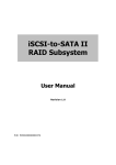
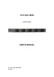
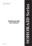
GR/iR2880-8S-U5 User Manual v.1.2 (February, 2011) Introduction About this Manual Thank you for using products of the RAIDON Technology Inc. This manual introduces the RAIDON GR/iR2880 SAS series products and briefs you about the operations of disk array (RAID) systems. Actual specifications of your products are subject to the physical ones shipped to you in spite of that contents of the Manual have been thoroughly reviewed before release. Updates of products specifications and/or any products related information may be made at any time without notice. Please visit our web site at www.raidon.com.tw or contact with local sales representatives for latest information. If you have any question with products of the RAIDON Technology Inc. or you need the latest product information, user’s manual and firmware please contact us at [email protected]. We’ll reply you as soon and fast as possible. NOTE: the RAIDON Technology Inc. only provides technical support and services to direct customers. For consumers and/or customers who bought our products at retailers or our dealers please contact them for better supports and faster services. If your products are not purchased directly from the RAIDON Technology Inc. please do not contact us for supports as you may get no response from us. Related product information in this Manual is copyright © RAIDON Technology Inc. All rights reserved. Contents Chapter 1 Introduction to disk array (RAID).......................................... 5 1.1 1.2 1.3 Chapter 2 2.1 2.1.1 2.1.2 2.1.3 2.2 2.2.1 2.2.2 2.2.3 2.3 2.3.1 2.3.2 2.3.3 2.4 2.4.1 2.4.2 2.4.3 Chapter 3 3.1 3.2 3.3 3.4 3.4.1 3.4.2 3.4.3 3.4.4 3.4.5 3.5 3.5.1 Disk array (RAID)........................................................................... 5 Functions of disk array.................................................................... 5 Terminology.................................................................................... 5 Installation................................................................................... 7 Pre-cautions................................................................................... 7 Features of the RAIDON SAS series products............................... 7 Confirmation of related items......................................................... 7 Inside the box................................................................................. 8 Installation...................................................................................... 8 Hardware........................................................................................ 8 LED indications.............................................................................. 9 Hardware installation...................................................................... 10 Log into the administration interface.............................................. 11 Web GUI........................................................................................ 12 RS232 (Super Terminal)................................................................. 13 Secure Shell................................................................................... 15 Embedded controlse...................................................................... 16 LCM................................................................................................ 16 System buzzer................................................................................ 18 LED................................................................................................ 18 Introduction to the GUI............................................................ 19 Structure of the GUI....................................................................... 19 Login............................................................................................... 20 Quick installation............................................................................ 21 System configuration...................................................................... 22 System setting................................................................................ 23 IP address...................................................................................... 23 Login setting................................................................................... 24 Mail setting..................................................................................... 25 Notification setting.......................................................................... 25 Disk drive configuration.................................................................. 26 Volume creation wizard.................................................................. 26 3.5.2 3.5.3 3.5.4 3.5.5 3.5.6 3.6 3.6.1 3.6.2 3.6.3 3.6.4 3.7 3.7.1 3.7.2 3.7.3 3.7.4 3.7.5 3.7.6 3.7.7 3.8 Physical disk................................................................................... RAID group..................................................................................... Virtual disk...................................................................................... Snapshot........................................................................................ Logical unit..................................................................................... Enclosure management................................................................. SES configuration.......................................................................... Hardware monitor........................................................................... S.M.A.R.T....................................................................................... UPS................................................................................................ System maintenance...................................................................... System information......................................................................... Upgrade.......................................................................................... SAS................................................................................................ Reset to factory default.................................................................. Import and export........................................................................... Event log........................................................................................ Reboot and shutdown.................................................................... Logout............................................................................................ 27 29 31 35 37 37 37 38 38 38 39 39 40 40 40 41 41 41 41 Chapter 1 Introduction to disk array (RAID) 1.1 Disk array (RAID) Individual hard disk, either SCSI or IDE type, is subject to the matching problems between revolution speed of driving motor and transmission interface. Transmission speed of an Ultra 160 SCSI or ATA100 IDE hard disk may have a limit of 30MB/Sec at the bandwidth of 100MHz. With limited lifespan any disk failure may lead to the disaster of system broken and data loss. Both are critical to any network environment. A new device, the so called Redundant Arrays of Inexpensive / Independent Disks (RAID) is then created by combining several independent disks into a hard disk group for better transmission and storage performance. A disk array combines two or more than two physical disk drives into a virtual/logical disk system with on-line, fast access, large capacity and fault tolerant features by Striping, Mirroring and Parity Checking mechanism. A disk array then may continue its normal operation without causing any system failure or data loss when any one drive in the array is out of work. In short the RAID technique improves efficiency and data integrity for any network configuration. 1.2 Functions of disk array • Enhance storage capacity • Improve data access speed • Reduce cost • Inherent fault tolerance • Hot swap • Auto data rebuilding • Hot spare • On-line capacity expansion 1.3 Terminology The following terms are used in this Manual: RAID Redundant Array of Independent Disks PD Physical Disk RG Raid Group VD Virtual Disk LUN Logical Unit Number GUI Graphic User Interface WT Write-Through Introduction to disk array (RAID) 5 WB Write-Back RO Read-Only DS Dedicated Spare disks GS Global Spare disks DC Dedicated Cache GC Global Cache DG DeGrade mode S.M.A.R.T. WWN Self-Monitoring Analysis and Reporting Technology. World Wide Name HBA Host Bus Adapter MPIO Multi-Path Input/Output 6 Introduction to disk array (RAID) Chapter 2 Installation 2.1 Pre-cautions 2.1.1 Features of the RAIDON SAS series products Features of the RAIDON SAS series products: • Employs 2.5” SATA HDD • Dual SAS tunnel • Support RAID 6 • Support hot swap • N-way mirroring • Snapshot function • GUI • Volume based share/exclusive cache configuration • Support S.M.A.R.T • Support SAF-TE • Disk roaming The RAIDON SAS series products may provide non-stop services with high fault tolerance when installed properly. The RAIDON SAS series products connect to related system via the SAS interface and can be configured at any RAID level for reliable data protection. At RAID 6 level there can be 2 failed disks without damaging existing data. Data stored in the damaged hard disk(s) can be recovered from that kept in the normal running hard disks. The RAIDON SAS series products are the best and most economical data storage backup solution for small and medium enterprise users. 2.1.2 Confirmation of related items Before installing your product please ensure the following items: • When removing objects out of the shipping carton please ensure that all the items are in there and not damaged • Please read the latest release before updating your firmware • Ensure your server is equipped with a SAS HBA card • A piece of CAT 5e or CAT 6 network cable for the GUI administration port • Ready your storage system configuration plan • Network data of the GUI administration port. For fixed IP please make the data of your IP address, sub-network mask and default gateway available in advance. (Contact your MIS personnel for above data.) • Make all the hardware, power and wires for COM port and Administration port (LAN or RS232), ready before powering on your system. Installation 7 2.1.3 Inside the box Items contained in the shipping carton are listed below: Item iR2880-8S-U5 GR2880-8S-U5 Main body • • External RS232 cable • • Internal RS232 cable • ▬ MiniSAS cable (MiniSAS to MiniSAS) ▬ • AC Power cable ▬ • Quick installation guide • • CD (the User’s Manual included) • • Accessory kit • • 2.2 Installation 2.2.1 Hardware 8 Installation 2.2.2 LED indications LED Status Host Access-1/2 Fan Failure Controller Status HDD ▬ Red / Lights On Blue / Lights On Red / Lights On Blue / Lights On ▬ Blue / Lights On Blue / Blinks Fan Failure Blue / Lights On Red / Lights On & Buzzer Alarm Red / Lights On ▬ Accessing Blue & Purple / Blink Alternatively ▬ Blue / Lights On Blue / Blinks HDD Idling Blue / Lights On ▬ Blue / Lights On ▬ HDD failure Blue / Lights On ▬ Red / Lights On & Buzzer Alarm ▬ Rebuilding Blue / Lights On ▬ Red / Lights On Source : Blue / Blinks Target : Blue & Purple / Blink Alternatively Power on (booting) RAID building Installation 9 2.2.3 Hardware installation Please install your RAIDON SAS series product by following steps listed below: Note : The following steps are for the iR2880-8S-U5 model. For GR2880-8S-U5 model please skip Step 5. Step 1 Open the shipping carton, remove the main body of your product out of the carton and place it on a working bench. (Please make sure that no item is missed or damaged. If there is any doubt please contact with your dealer or sales representative.) Step 2 Unlock the HDD removable tray by pressing the removable tray lock leftwards (press left to unlock and right to lock). Press and push the removable tray release button to remove the tray. Step 3 Insert the SATA disk drive in the HDD removable tray and ensure the disk fastening screws are securely locked to prevent disk damage caused by un-intentional movements from happening. 10 Installation Step 4 Insert the disk-installed-tray back in the main body. Make sure that it is inserted completely and press the removable tray lock on top of it to the LOCK position. Step 5 Make sure there is adequate space for three CD-ROM drives inside your computer case. Install the full iR2880 main body within the case and fix it with supplied fastening screws. (You may have to bend the battle between CD-ROM drives to horizontal position for proper iR2880 installation.) Step 6 Insert connecting cables to corresponding connectors respectively. Make sure that the two SAS ports and the four power ports are connected to proper cables and devices. Note: the GR2880 model needs connecting to external power line only. Both the LAN and RS232 ports are for GUI connection. You can select either one for installation. (Check the adequacy of your power supply wattage to ensure successful operation of your iR2880 product.) Step 7 The installation is completed. You may power on your computer system for setup and application. 2.3 Log into the administration interface You may login and manage your RAIDON SAS series products by following three steps described below: Installation 11 2.3.1 Web GUI The RAIDON SAS series products support GUI for system management. Make sure that related LAN port is connected in advance. For network environment with a DHCP server your RAIDON SAS series products can get IP address automatically. You may get the IP address through LCM of the equipment. See Chapter 3 for required settings. For network environment without a DHCP server your RAIDON SAS series products can be connected by specifying an IP address manually. See descriptions below for required settings. (The default IP address of your RAIDON SAS series product is 192.168.0.1.) Step 1 Check for IP address conflict in advance. Please contact your system administrator for confirmation. Step 2 Local area network (LAN) setup. Select the Local Area Connection Status dialog box by click the Control Panel → Network connection → Local Area Connection items. Click the Properties icon to select it. Step 3 Select Internet Protocol (TCP/IP) and click the Properties icon. The Internet Protocol (TCP/IP) setup screen displays. 1 2 12 Installation Step 4 Set up the IP address, Subnet mask, Default gateway and DNS. The IP address and Default gateway must be in the same domain (192.168.0.xxx) of your 2880 series product (Please contact your system administrator for confirmation.) Step 5 Click OK after you have filled in required values. (The IP address of your RAIDON SAS series product must remain in the same segment after any IP address change for successful system operation.) Step 6 Open your web browser and type http://192.168.0.1 in the URL field. You may type in https://192.168.0.1 to connect product in encrypted data transmission mode in the Secure Sockets Layer for better security at the expense of transmission speed. Step 7 A login dialog box displays after successful connection. Please enter your account name and password as required. (The default account/password is: admin / 1234.) Click the Login button to login the system. Refer to Chapter 3 for subsequent setup steps. 2.3.2 RS232 (Super Terminal) You may manage and set up the system with the Super Terminal function by connecting directly to the RS232 COM port. The same function can be used for system setup when the original IP address to your systen is lost. See steps below for operations at the Windows XP environment. Step 1 Connect to your system with the RS232 cable in the accessory kit supplied with your product. Turn on related power supply after successful connection. Step 2 Open your Super Terminal function by clicking the icons of Start → Programs → Accessories → Communication → Super Terminal. Start setting up your Super Terminal. The first step is to name this terminal. Installation 13 Step 3 Select COM port. (The COM port being connected.) Step 4 Type in required settings. Bits per second: 115200 Data bits: 8 Parity: None Stop bits: 1 Flow control: None Step 5 Select terminal type by clicking at File → Properties → Setup. Select type “VT100”. Select OK to finish setup operation. 14 Installation Step 6 Type in your account/password to log in your terminal after connection. Please refer to Chapter 3 for operation in similar web GUI mode. (The default account/password is: admin / 1234.) 2.3.3 Secure Shell Your RAIDON SAS series product may be connected by way of Secure Shell (SSH) for better data transmission security. The SSH client software can be downloaded at the following web sites: SSH Win Client WWW: http://www.ssh.com/ Putty WWW: http://www.chiark.greenend.org.uk/ The default IP address: 192.168.0.1 (Type in your new IP address if you have made changes to it.) User name: admin Default password: 1234 Type in account/password to log in your terminal after connection. Please refer to Chapter 3 for operation in similar web GUI mode. Installation 15 2.4 Embedded controls 2.4.1 LCM You may control the LCD Control Module (LCM) by pressing the four function keys of ▲ (up), ▼(down), ESC (exit) and ENT (select). A screen as shown below displays after the system is turned on: XXX . XXX . XXX . XXX RAIDON GR2880U5 Press the ENT (select) key then press the ▲ (up) and ▼(down) keys to select the LCM functions. When there is any warning or error encountered a proper screen message is displayed by the LCM for providing more information to its users. The LCM functions are summarized below: Alarm Mute Turn off the alarm sound when there is error encountered Reset/Shutdown Reset or shutdown the controller Quick Install Fast set up a volume in three steps. See Paragraph 3.3 for operation in web GUI mode. View IP Setting Display existing IP address, Subnet mask and Default gateway. Change IP Config Set up the IP address, Subnet mask and Default gateway. You may choose to use DHCP, get IP address from your DHCP server) or specify fixed IP address. Reset to Default Reset to factory default values. Default password: 1234 Default IP address: 192.168.0.1 Default Subnet mask: 255.255.255.0 Default gateway: 192.168.0.254 LCM configuration reference table RAIDON GR/iR2880U5 ▲▼ 16 Installation [System Info.] [Alarm Mute] [Reset/Shutdown] [Firmware Version x.x.x] [RAM Size xxx MB] [▲Yes No▼] [Reset] [▲Yes No▼] [Shutdown] [▲Yes No▼] RAID 0 RAID 1 RAID 3 [Quick Install] RAID 5 [Apply The Config] [▲Yes No▼] [Use default [Volume Size] algorithm] xxx BG RAID 6 RAID 0+1 xxx GB [Local] RAID 0 RAID 1 RAID 3 RAID 5 [Apply The Config] [▲Yes No▼] RAID 6 [Volume Wizard] RAID 0+1 [JBOD x]▲ ▼ RAID 0 RAID 1 RAID 3 RAID 5 [new x disk]▲ ▼ Adjust xxx BG Volume Size [Apply The Config] [▲Yes No▼] RAID 6 RAIDON RAID 0+1 GR/iR2880U5 [IP Config] ▲▼ [Static IP] [IP Address] [View IP Setting] [192.168.010.050] [IP Subnet Mask] [255.255.255.0] [IP Gateway] [192.168.010.254] [DHCP] [▲Yes No▼] [IP Address] [Change IP Config] [Static IP] [IP Subnet Mask] [IP Gateway] [Apply IP Setting] [Reset to Default] address Adjust Submask IP Adjust Gateway IP [▲Yes No▼] [▲Yes No▼] [Phy. Disk Temp.] [Enc. Management] Adjust IP [Cooling] [Power Supply] [Slot X : XX(°C)] NONE FAN X:XXXXRPM NONE Installation 17 Note : Please proceed "Shutdown" to erase the cache memory in the physical hard disk for better data protection. 2.4.2 System buzzer Functions of the system buzzer are: 1. Beep for one second after successful system power on. 2. Beep continuously when there is any system failure or error encountered. You may turn off the alarm sound by selecting the Alarm Mute option. 3. The alarm sound turns off automatically when the system failure or error is solved. 2.4.3 LED Your RAIDON SAS series product is featured with LED indicators for system status. You may check system status by viewing indicator lights. 18 Installation Chapter 3 Introduction to the GUI 3.1 Structure of the GUI The GUI is described below: Quick Install → Step 1 / Step 2 / Confirm System setting → System name / Date and time / System indication IP address → MAC address / Address / DNS / Port Login setting → Login configuration / Admin password / User password Mail setting → Mail Notification Setting → SNMP / Messenger / System log server / Event log filter / Buzzer Volume creation wizard → Step 1 / Step 2 / Step 3 / Step 4 / Confirm Physical disk → Set Free disk / Set Global spare / Set Dedicated spare / Upgrade / Turn on the indication LED / More information RAID group → Migrate / Activate / Deactivate / Parity check / Delete / Set disk property / More information Virtual disk → Create / Extend / Parity check / Delete / Set property / Attach LUN / Detach LUN / List LUN / Set Clone / Set snapshot space / Cleanup snapshot / Take snapshot / Auto snapshot / List snapshot / More information Snapshot → Cleanup / Auto snapshot / Take snapshot Logical unit → Attach / Detach SES configuration → Enable / Disable Hardware monitor → Auto shutdown S.M.A.R.T. → S.M.A.R.T. for physical disks UPS → UPS type / Shutdown battery level / Shutdown delay / Shutdown UPS / Status / Battery level System information → System information / CPU type / Installed system memory / Controller serial no. / Backplane ID Upgrade → Browse the firmware to upgrade SAS → SAS topology Reset to factory default → Reset to factory default Import and export → Import / Export Event log → Show system events (Info / Warning / Error) System Configuration Volume configuration Enclosure management Maintenance Introduction to the GUI 19 Reboot and shutdown → Reboot / Shutdown Logout 3.2 Login Your RAIDON SAS series product supports a GUI operation mode. Please connect your network cable and make sure it is in the same network segment of other related devices. Please refer to Chapter 2 for required setup. Illustration below shows you how to log in the iR2880-8S-U5 model with default IP address. (The operation screens for the GR2880-8S-U5 model are the same as that of the iR28808S-U5 one except the model number shown at the upper left corner.) Open up your browser and type the following address in the URL field: http://192.168.0.1 A login dialog box prompts for input of account ID and password. The default ones are admin and 1234. Select menu items in left panel of the screen for system setup after successful login. Figure 3.2.1 There are 8 instruction icons at the upper right corner of your screen as described below: 1. Home: back to the home page 2. Logout: log out the system 3. Mute: mute the beeper 4. RAID: the RAID is in normal operation when it is in green color and failed when in red. 20 Introduction to the GUI 5. Temperature: the system temperature is normal when it is in green color and abnormal when in red. 6. Voltage: the system voltage is normal when it is in green color and abnormal when in red. Please refer to Paragraph 3.6.2 for more details. 7. UPS: the UPS is in normal operation when it is in green color and failed when in red. (The icon is in green color when no UPS is installed.) 8. FAN: the cooling fan is in normal operation when it is in green color and failed when in red. 3.3 Quick installation The Quick installation function assists you in creating a disk volume quickly. You are limited to specify the RAID level to 0, 1, 3, 5, 6 and 0+1 and to use volumes detected by the system automatically instead of adjusting volumes manually. The detected volume depends upon the number of drives and capacity of each drive installed earlier. The Quick installation function is an intelligent software program that lists out all the available RAID levels (0, 1, 3, 5, 6 and 0+1) and capacities. The Quick installation function uses all the available disk space based on your RAID selections automatically. You may learn that some hard disks are not utilized (free disk) caused by policies of the Quick installation function: 1. Provide the maximum capacity based on user specified RAID level. 2. Select the least number of disk drives based on the RAID level or volume size. The Quick installation function is exemplified below with the iR2880-8S-U5 model: Step 1: Select RAID level after the Quick installation function is selected. Please refer to the figure below. Click the Confirm button after choosing the RAID level to enter the next page. Figure 3.3.1 Introduction to the GUI 21 Step 2: Confirm the selected RAID level and capacity by clicking at the Confirm button if the selections are correct. The setup process is completed after confirmation. Figure 3.3.2 Step 3: The screen of Virtual disk options displays afterwards and the preliminary hardware setup is now completed. You may start using the system now. Figure 3.3.3 Note : 1.You can only select volume sizes provided by the system rather than adjusting volumes manually when configure the system with the Quick installation wizard. 2. For the RAID5 / RAID6 setup the advanced system configuration and use can be started only after successful system initialization. 3. You may set up the RAID10, 30, 50 and 60 in the Volume Configuration rather than selecting from the Quick installation function. 3.4 System configuration The System configuration option lets you configure the following settings: System setting, IP address, Login setting, Mail setting and Notification setting. 22 Introduction to the GUI Figure 3.4.1 3.4.1 System setting You may change the name of your system in the System name field. Figure 3.4.1.1 You may set up the system related time in the Date and time field. Type in the name of your NTP server if the Network Time Protocol (NTP) function has been selected. Figure 3.4.1.2 The System indication function assists you to find the desired equipment location by the LED indicator of itself when there are multiple RAIDON SAS series products installed in your system. The LED indicator lights (LED of Controller Status) can be found at the far right of the front of your product. Figure 3.4.1.3 3.4.2 IP address You may get the system MAC address and change related network setting in the IP address option. The default address is DHCP. You may change it to Static. Please validate related settings to prevent connection failure from happening. Introduction to the GUI 23 Figure 3.4.2.1 3.4.3 Login setting The Login setting option lets you set up system login related options including automatic logout time, login restrictions and login password. 1. Auto logout: available options are Disable, 5 min, 30 min and 1 hour. The user of the system is logged out by the system when no action has been taken by the user in given time span such that other users may log in the system. 2. Login lock: available options are Disable and Enable. Only one user can log in the system for changing system settings when the Disable option is selected. Figure 3.4.3.1 You may set up another login password with an account ID “user”. Users log in with the “user” account may be unable to change certain system settings as the corresponding functions are hidden with respect to these users. 24 Introduction to the GUI 3.4.4 Mail setting You may specify up to 3 email accounts for receiving notices of system events by selecting the Mail option. Some email servers may filter “Mail-from address” to block spam mails. Please fill in related data in the required fields and click the “Send test mail” option to validate email usage. You may need to get help from your system administrator for proper settings of related system setup. You may select types of events that need to be informed. The default event types are the Error and Warning ones. You are required to set up the SMTP reply option if the notice emails are to send to external email boxes via SMTP. You need the account ID and password of your SMTP server to do proper setups. Figure 3.4.4.1 3.4.5 Notification setting You may set up the Simple Network Management Protocol (SNMP) of your system in the SNMP field. You may specify up to 3 SNMP address with default community of “public”. You may select pattern of event log. The default SNMP keeps message log only. Select “Download” to download the MIB file. You may need to get help from your system administrator for proper settings of related system setup. Figure 3.4.5.1 You may send related messages directly to specified computers with instant messaging systems . (The IM function of the computer must be ready in advance. This function is supported by Windows XP SP2 or earlier versions.) Introduction to the GUI 25 Figure 3.4.5.2 You may send the related log files to a log server if you have installed one. Required setup values can be provided in the System log server screen. Figure 3.4.5.3 You may select to display desired information with the Event log filter function. Figure 3.4.5.4 You may turn on and off the beeper of your system with the Buzzer function. Figure 3.4.5.5 3.5 Disk drive configuration Options available in the Volume configuration menu are: Volume creation wizard, Physical Disk, RAID group, Virtual disk, Snapshot and Logical unit. Figure 3.5.1 3.5.1 Volume creation wizard The Volume creation wizard assists you to set up the system easily. Its function is similar to that of the Quick installation one. However you can select desired disk drive combinations with the Wizard. Step 1: Select desired RAID levels of 0, 1, 3, 5, 6 and 0+1. 26 Introduction to the GUI Figure 3.5.1.1 Step 2: Select to accept one of the pre-defined disk drive combinations or to configure a new one by yourself. Figure 3.5.1.2 Step 3: Setup capacity of disk volume. (The default size is the whole available space.) Figure 3.5.1.3 Step 4: Confirm settings given by you. Figure 3.5.1.4 Select Confirm and the Virtual disk menu appear with the newly set up disk drive. Figure 3.5.1.5 3.5.2 Physical disk The Physical disk function helps you to view status of hard disks now installed in your system. Figure 3.5.2.1 Introduction to the GUI 27 For hard disk being set up as a RAID drive the text “RAID disk” may show up in the Usage field or the “Free disk” message is display instead. See Figure3.5.2.1 for illustration. You may click buttons below the slot numbers to give instructions to individual hard disk. The Status and Usage fields display related information afterwards (see Figure3.5.2.2). 1. Set Free Disk This function can be used only for disks that have been set to certain RAID level. The RAID that contains the released disk will downgrade automatically. If you have chosen Global / Dedicated spare function the Rebuilding operation will be initiated automatically. 2. Set Global Spare You may set up hard disks at status of Free disk to be a Global spare one. If one of the disk drives in the RAID fails the RAID system will be rebuilt with the Global spare disk. 3. Set Dedicated Spare You may set up hard disks at status of Free disk to be a Dedicated spare one for specific RAID level. If one of the disk drives in the RAID fails the RAID system will be rebuilt with the Dedicated spare disk at top priority. 4. Upgrade This function upgrades the firmware of hard disks directly. For disks in the process of rebuilding or other operations the upgrade process takes place only after the in-process operations are completed. (This function supports the WD and Seagate drives now.) 5. Turn on the Indication LED You may use function to identify the actual location of failed hard disks if the existing LED indicator light fails to do so. 6. More Information This function assists you to get more details about individual hard disks as shown in Figure3.5.2.3. Figure 3.5.2.2 Figure 3.5.2.3 28 Introduction to the GUI Field descriptions for physical hard disks: Slot The hard disk ID. Click the blue button below individual number to display details about given disks. Size Change the unit of disk volume to GB or MB. RG Name of the RAID Group. Status Current hard disk status. “Online” → the hard drive is online. “Rebuilding” → the hard drive is being rebuilt. “Transition” → the hard drive is being migrated or is replaced by another disk when rebuilding occurs. Health Health status of hard disks. “Good” → the hard drive is good. “Failed” → the hard drive is failed. “Error Alert” → S.M.A.R.T. error alert. “Read Errors” → the hard drive has unrecoverable read errors. Usage Current hard disk settings. “RAID disk” → This hard drive has been set to a RAID group. “Free disk” → This hard drive is free for use. “Dedicated spare” → This hard drive has been set as dedicated spare of a RG. “Global spare” → This hard drive has been set as global spare of all RGs. Vendor Name of hard disk supplier. Serial Serial number of hard disk. Type Interface specification of hard disk. Write cache With or without write cache. Default is “Enabled”. Standby Set a hard disk into sleep mode and stops revolving the drive for energy saving after it is idle (without any read and write activity) for predefined period of time. Default is “Disabled”. Readahead The “readahead” function pre-reads segment data potentially required in the future into system buffer to speed up reading activities. Default is “Enabled”. Command queuing This is the so-called NCQ function. It optimizes a series of read and writes instructions in advance to speed up their executions. Default is “Enabled”. 3.5.3 RAID group The RAID group function lets you view, manage and create RAID group. Click the Create icon to create a group of new RAID settings. You can select hard disks used by the RAID group with the Select PD option. Introduction to the GUI 29 Figure 3.5.3.1 Click Confirm and settings of the newly created RAID group displays. Figure 3.5.3.2 You may set up additional Migrate, Move, Active, Deactivate, Parity check, Delete, Set disk property and More information options for the newly set up RAID group. Figure 3.5.3.3 Select the Migrate function to expand the existing RAID group or change the RAID level settings. Figure 3.5.3.4 Select the Move function to move the existing RAID group or change the RAID level to other disks. (Disk volume after movement must be no less than its current one or the movement fails.) Figure 3.5.3.5 For RAID group at Offline state you may select Active to activate it or Deactivate and Delete to disable and delete it respectively. 30 Introduction to the GUI Figure 3.5.3.6 The Set disk property function can be used to change settings of given RAID group including: Write cache, Standby, Readahead and Command queuing. Figure 3.5.3.7 The More information option displays detailed information of given RAID group. Figure 3.5.3.8 3.5.4 Virtual disk You may view status of each virtual disk with the Virtual disk function. At the host system end what the device administrator can see are virtual disks set up previously. If no virtual disk has been set up then there will be no available you can find at the host end. Click Create to set up a new RAID group then click Select PD to select hard disk for it. Figure 3.5.4.1 Field description: No. Virtual disk ID. Click the button below individual ID for detailed setups. Name Name of current disk drive. Size Capacity of the virtual disk. Can be expressed in unit of GB or MB. Introduction to the GUI 31 Write WT = Write-through cache WB = Write-back cache RO = Read-only Priority High / Middle / Low priorities between virtual disks. Bg rate 0~4, with default at 4. The bigger the number the higher performance ratio for its background jobs (like Rebuilding). Status Status of virtual disk. “Online” → The virtual disk is online. “Offline” → The virtual disk is offline. “Initiating” → The virtual disk is being initialized. “Rebuild” → The virtual disk is being rebuilt. “Migrate” → The virtual disk is being migrated. “Rollback” → The virtual disk is being rolled back. “Parity checking” → The virtual disk is being parity Clone VD Backup Schedule Scheduled Backup Type States being set up. “RAID” → the virtual disk is normal. “BACKUP” → the virtual disk is for clone usage. Health Health status of virtual disk. “Optimal” → the virtual disk is working well and there is no failed disk in the RG. “Degraded” → At least one disk from the RG of the Virtual disk is failed or plugged out. “Failed” → the RAID group disk of the VD has single or multiple failed disks than its RAID level can recover from data loss. “Partially optimal” → the virtual disk has experienced recoverable read errors. After passing parity check, the health will become “Optimal”. R% Progress % of rebuilding. RAID RAID level. #LUN Number of LUN. Snapshot space Space reserved for Snapshot. The number means “Used snapshot space” / “Total snapshot space”. #Snapshot Number of snapshot. RG name Name of the attached RAID group. 32 Introduction to the GUI Click the button below each number to do detailed setup as described below. Figure 3.5.4.2 1. Extend This option lets you expand capacities with space not used by RG. 2. Parity check This option lets you do parity check against selected disk. This option is available to redundant RAID level 3, 5, 6, 30, 50 and 60 only. Figure 3.5.4.3 3. Delete Delete selected virtual disk. (Data stored in the disk is erased at the same time.) 4. Set property Set up properties for virtual disks (like accessing limits). Figure 3.5.4.4 AV-media mode: this is a special function for AV editing and monitoring systems to avoid instantaneous video frame losses by regulating the I/O bandwidth effectively. 5. Attach / Detach LUN Add or remove selected LUN. 6. List LUN Display related LUNs. Introduction to the GUI 33 7. Set clone Set dedicated VD for backup, please select the type as “Backup” when creating VD, so that the VD can be designated for Clone, and it only workable when the volume size of VD is equal to or bigger than the VD which it will backup from. Additional instructions will appear after setting as the followings: Start clone: Clone operation begins Stop clone: Clone operation stops Schedule clone: Clone auto-activation scheduling 8. Set snapshot space Setup the size of Snapshot. (Please refer to paragraph 3.5.5 Snapshot for description.) 9. Cleanup snapshot Erase all the Snapshots in given virtual disk. 10. Take snapshot Create new Snapshot immediately. 11. Auto snapshot Set up automatic and regular execution of the Snapshot function. (Please refer to paragraph 3.5.5 Snapshot for description.) 12. List snapshot Display all the Snapshot data. 13. More information Display complete information of the entire virtual disk. Figure 3.5.4.5 Under the options of Virtual disk, click on “Configuration” to setup the Clone Configuration, if Snapshot has not been setup at this point, system will follow the Clone settings to create Snapshot, and if Snapshot has already been setup, then system will correspond to the configured settings of Snapshot. (Please refer to Paragraph 3.5.5 for Snapshot) Figure 3.5.4.6 Figure 3.5.4.7 34 Introduction to the GUI Snapshot space: there are six options from selection of 0.5, 1, 1.5, 2, 2.5 and 3 (default is at 2), these numbers representing the multiple ratios for the VD., For example, when multiple ratio is at "2" and VD is 100GB, system will create a volume of 200GB for Snapshot space. Threshold: there are three options in percentage from Snapshot space usage of 40%, 50% and 60%. When Snapshot space usage exceeding selected percentage, system will take one snapshot automatically. Restart the task an hour later if failed: When a Snapshot failed, system will delete all existing Snapshot and auto-create new Snapshots after one hour. Note : These functions only for the Snapshot which be created from Clone, it will not be functional by manual setting Snapshot. 3.5.5 Snapshot The Snapshot function stores current data and settings with a recover point such that system can be restored to selected recovery status for the prevention of virus attack, system failure and human errors. It is recommended to reserve as large as possible from the VG space for Snapshot storage and the minimum requirement of snapshot space is 1GB. More of Snapshot settings can be configured under “Snapshot option”. Figure 3.5.5.1 1. Cleanup snapshot Erase all the Snapshot data in given virtual disk. 2. Auto snapshot Set up the system to run Snapshot function regularly and automatically. Figure 3.5.5.2 Introduction to the GUI 35 3. Take snapshot Create new Snapshot immediately. Note : Snapshot function is not as creating identical data for backup, it is based on existing database recovering to different Snapshot stages, if the database is damaged or formatted, it may not be workable for system recovery. Also if the changes of data volume is over the configured Snapshot volume, then the entire Snapshots will be failed, therefore, it is highly recommended that user should aware of total available volume of snapshot while using this function. Snapshot field description: No. Snapshot ID. Click the button below individual ID for detailed setups. Name Name of Snapshot. Used Capacity of the Snapshot. Can be expressed in unit of GB or MB. Status Status of Snapshot. “N/A” → The snapshot is normal. “Replicated” → The snapshot is for clone usage. “Abort” → The snapshot is over space and abort. Health Health status of Snapshot. “Good” → The snapshot is good. “Failed” → The snapshot fails. Exposure To display Snapshot VD exposures Snapshot or not Right Default is “Read-only” #LUN Number of LUN. Created time Creation time of Snapshot. Click the button below individual ID for detailed setups as described below. Figure 3.5.5.3 1. Expose / Unexpose To display Snapshot VD 2. Rollback Restore the system back to state of given Snapshot. 3. Delete Delete Snapshot. 4. Attach (appear only after being exposed) Assign LUN for given Snapshot. 36 Introduction to the GUI 5. Detach (appear only after being exposed) Remove LUN for given Snapshot. 6. List LUN (appear only after being exposed) Display list of all the connected LUN. 3.5.6 Logical unit Entering the Logical unit function to view/add logical units attached to each virtual hard disk. Figure 3.5.6.1 Click the button below Host ID to delete given LUN. Each virtual disk must have one dedicated LUN attached to it. Without this the selected volume is unusable 3.6 Enclosure management The Enclosure management option lets you set up and manage the SES configuration, Hardware monitor, S.M.A.R.T. and UPS related functions. Figure 3.6.1 3.6.1 SES configuration Switch on and off the SES connection between selected Host and LUN. The SCSI Enclosure Services (SES) enable you to access data of power, temperature and other hardware monitoring inside the cabinet with SCSI commands from the host end. Extra third-party software is required at the host end for this. Please refer to the SANtools documents available at http://www.santools.com/. Figure 3.6.1.1 Introduction to the GUI 37 3.6.2 Hardware monitor Select the Hardware monitor function to view current voltage and temperature. Figure 3.6.2.1 Please check the Auto shutdown option to shut down your system when the voltage and temperature are over the normal operational range for better data protection. 3.6.3 S.M.A.R.T. The Self-Monitoring Analysis and Reporting Technology (S.M.A.R.T.) is a hard disk diagnostic tool that alerts you of disk failure in advance. This gives you an opportunity to take preventative actions before the disk is failed. The S.M.A.R.T. function keeps on monitoring various properties of your hard disk and alerts you when specific disk is reaching its capacity. The pre-set disk failure notice helps you replace or backup it in advance. This is better than left with a failed disk or having to rebuild a new one. Select the S.M.A.R.T. option to display the S.M.A.R.T. data of your hard disk. Number in front of the parenthesis represents current value while within it for default value. Default values differ among brands of disks. Please refer to the user manual for detailed specification of your disks. Figure 3.6.3.1 3.6.4 UPS Select the UPS option to set up your Uninterruptible Power Supply (UPS). Figure 3.6.4.1 38 Introduction to the GUI The system now supports the smart-UPS function provided by the American Power Conversion Corp. (APC) UPS of other suppliers are acceptable but without the related setup function. UPS Type Select types of UPS. For APC UPS please select Smart-UPS or None for any other one. Shutdown Battery Level (%) The system shuts down automatically when battery capacity is lower than given limits. Set the limit value to zero to shut down your UPS. Shutdown Delay (s) In case of power failure and it lasts longer than the delay seconds of power off the system shuts down automatically. Set the value to zero to turn off this function. Shutdown UPS Select ON to power off your UPS after successful system shut down in case of power failure. After the power supply resumes the system will be turn on after the UPS is initiated. Select OFF to stop all the above actions. Status Status of UPS: “Detecting…” “Running” “Unable to detect UPS” “Communication lost” “UPS reboot in progress” “UPS shutdown in progress” “Batteries failed. Please change them NOW! ” Battery Level (%) Remaining battery power in percentage. 3.7 System maintenance The Maintenance function helps you do preliminary troubleshooting with simple viewing and operation in case of system failure. Available functions are: System information, Upgrade, SAS, Reset to factory default, Import and export, Event log and Reboot and shutdown. Figure 3.7.1 3.7.1 System information Select System information for viewing current system information including: Model No., CPU Type, Installed system memory, Controller serial no. and Backplane ID. Introduction to the GUI 39 Figure 3.7.1.1 3.7.2 Upgrade Select the Upgrade function for firmware upgrade. Get the new firmware version (with name in format of xxxx.bin). Click Browse to scroll and select the file. Click Confirm and the upgrade will complete automatically. Figure 3.7.2.1 There will be a progress bar displayed during firmware upgrading. Please re-start your system after firmware upgrade. Note : You don’t need to upgrade your firmware if your hardware is functioning normally. This frees you from operation abnormality after upgrade. Upgrading firmware carelessly may void settings of the whole system or even lead to data loss. Under no circumstances will RAIDON Technology Inc. be liable in any way for this kind of damage. Should you have any firmware upgrade requirements please contact [email protected] for latest firmware version. Select the Export configuration option to enter the Import and export function. 3.7.3 SAS Select the SAS option to access related data of SAS devices currently connected to the system. Figure 3.7.3.1 3.7.4 Reset to factory default Select the Reset to default option to restore your system to its factory default state. Figure 3.7.4.1 40 Introduction to the GUI 3.7.5 Import and export Select the Import and export option to import and export setup related values. Figure 3.7.5.1 3.7.6 Event log Select the Event log option to view the log of events starting from system creation to this moment. You may select “Download” to download related log file, “Mute” to turn off alarm sounds caused by events and “Clear” to erase existing entries. Figure 3.7.6.1 3.7.7 Reboot and shutdown Select the Reboot and shutdown option and both Reboot and Shutdown buttons appears. Please click the Shutdown button to erase the cache memory in the physical hard disk for better data protection. Figure 3.7.7.1 3.8 Logout Select the Logout option to log out your system directly. Type in your user name and password to login the system again. Introduction to the GUI 41