1
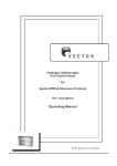
EasySun Pump Kit 1 Operating and Installation Manual EasySun Pump Kit Direct PV Pump Operating and Installation Manual Connection and Control Variable frequency drive MU-75-H 2 EasySun Pump Kit Operating and Installation Manual MU-75-H EasySun Pump Kit 3 Operating and Installation Manual Introduction As manufacturer of this electronic pump equipment, Atersa would like to thank you for choosing the EasySun Pump direct solar pump system. The EasySun Pump has been built and designed to guarantee a long life and reliability, allowing you to get the best performance from your pump system. Atersa has a wealth of experience in solar pump systems. In 1992, we designed and built the first pump devices for photovoltaic systems, which has allowed us to develop a series of alternatives and accessories to complement our main line of equipment and help obtain the best design and installation for individual applications. The company is ISO-9001 quality certified (ER-0979/1/97), issued and audited by the Spanish Association for Standardisation and Certification (AENOR), for the full product cycle, all the way from design through to the production and distribution of manufactured equipment. At Atersa, we welcome your comments as part of our process of continuous improvement. KEEP THIS MANUAL This manual contains important instructions for the EasySun Pump Model, which must be followed during installation and maintenance of the equipment. MU-75-H 4 EasySun Pump Kit Operating and Installation Manual MU-75-H EasySun Pump Kit 5 Operating and Installation Manual Contents Introduction ................................................................................... 3 Contents ......................................................................................... 5 Symbols Used ................................................................................. 6 Glossary of Technical Terms and Abbreviations .............................. 7 Regulatory Compliance ................................................................... 7 Safety Instructions ......................................................................... 8 Package Contents Inspection Sheet .............................................. 11 A. Delivery Company Receipt ..................................................... 11 B. Package Contents ................................................................. 11 Description of the Device .............................................................. 12 A. Overview of the Device .......................................................... 13 B. Installation Overview ............................................................ 14 C. Physical Properties ESP-3L / ESP-5L ........................................ 15 D. Inputs and Outputs (IO) ........................................................ 17 E. Electrical characteristics ........................................................ 19 F. Monitoring of Data ................................................................ 20 G. Pump Controller Block Diagram .............................................. 22 H. START/STOP Switch .............................................................. 22 Installation of the Equipment ....................................................... 23 A. Photovoltaic generator........................................................... 23 B. Location of the EasySun Pump (Controller and Variable Frequency Drive) with Respect to the Pump. ............................... 23 C. Mounting of the EasySun Pump .............................................. 25 D. Mounting the Pump: Motor ..................................................... 26 E. ESP Pump Controller Cable Inputs........................................... 26 F. Cable Routing....................................................................... 27 G. Earth Connections ................................................................. 27 H. Electrical Connection Properties .............................................. 28 I. Connection Diagrams ............................................................ 31 J. EasySun Pump Connection and Commissioning......................... 38 K. Removal .............................................................................. 41 Advanced Options for Technical Servicing..................................... 42 A. Problems When Commissioning the Installation ........................ 42 B. Supervision of Installation...................................................... 42 EasySun Pump Technical Specifications ........................................ 43 Maintenance ................................................................................. 45 Guarantee Terms and Conditions .................................................. 46 Trademarks ................................................................................... 47 Modifications ................................................................................ 47 MU-75-H EasySun Pump Kit 6 Operating and Installation Manual Symbols Used This manual makes use of graphic symbols to warn or inform the user of various situations of special importance. The symbols and their meanings are shown below. LIST OF SYMBOLS: Symbol: Description: INFORMATION: Additional information to be kept in mind. Used for important notes and reminders. WARNING: Situation that may result in serious damage to equipment and minor harm to people. DANGER: Instructions that must be observed. Failure to observe the instructions appearing alongside this symbol may result in an accident with serious consequences. INSPECTION ON RECEIPT: Indicates the steps to be followed when opening the packaging upon receipt of the equipment. USER: User manual. Using the equipment, menus, alerts and other functions. Installation and commissioning. INSTALLER: Maintenance and supervision manual. Advanced menu options. MU-75-H EasySun Pump Kit 7 Operating and Installation Manual Glossary of Technical Terms and Abbreviations Term Description PV AC Alternating current Photovoltaic DC Direct current DC line ER Line running from the solar modules to the panel Earth connection. Regulatory Compliance (Note: more information on certifications at www.atersa.com) • European Electromagnetic Compatibility Directive 2004/108/EC o EN 61000-6-2:2005. Immunity Industrial environment for industrial environments. o EN 61000-6-4:2007. Electromagnetic Compatibility. Industrial environments. • CE Marking Directive 93/68/EEC • Low-Voltage Electro-Technical Regulations (Royal Decree 842/2002) MU-75-H EasySun Pump Kit 8 Operating and Installation Manual Safety Instructions It is extremely important to read this section. The voltages present in the pump control panel are extremely dangerous to people. This equipment uses dangerous voltages. It is extremely important to carefully read and follow the instructions in this manual. Failure to follow these instructions may result in severe consequences, such as the destruction of the equipment, personal injury or even death by electrocution. CAUTION Do not open cover, danger of electric shock. There are no useraccessible parts inside. Maintenance must only be carried out by qualified technicians. A photovoltaic installation is a restricted area and must only be accessed by qualified technicians. The EasySun Pump must only be installed or opened by trained and qualified technicians approved by the supplier. Do not use the product if any of the mechanical or electrical components are defective. CAUTION: When the series of solar panels are exposed to light, they supply the equipment with DC power. CAUTION: Use resources and tools with sufficient insulation to protect against the working voltage of 1 kV DC when removing and inserting fuses and the cartridges included in the fuse carriers. NEVER OPEN FUSE CARRIERS WHEN THERE IS POWER IN THE SYSTEM, WITH THE PUMP OPERATING (with the exception of the START/STOP fuse carrier switch). CAUTION: NEVER OPEN FUSE CARRIERS without first opening the START/STOP fuse carrier for the pump and waiting a few seconds for the system to stop. Start/Stop switch MU-75-H EasySun Pump Kit 9 Operating and Installation Manual This process is required for: Handling fuses. Connecting or disconnecting the cables of the DC line both for the series of panels and the variable frequency drive output. Before connecting or disconnecting the DC line cables, it is essential to open all the fuse carriers in the pump control panel, starting with the START/STOP carrier, followed by the panel inputs and then the variable frequency drive outputs (ESP-3L only), removing the fuses from the panel series. To power down the variable frequency drive, first open all the fuse carriers in the pump control panel then use a volt meter to check the input voltage to the variable frequency drive is below 24 V DC to be able to handle the variable frequency drive (discharge of internal capacitors). CAUTION: To protect against the risk of fire, if necessary, all fuses must be replaced by identical models. CAUTION: DANGER OF ELECTRIC SHOCK. THE DC CONDUCTORS OF THE PHOTOVOLTAIC SYSTEM ARE NOT EARTHED AND MAY BE ENERGISED. CAUTION: NON-METAL HOUSINGS DO NOT PROVIDE AN EARTH CONNECTION BETWEEN CONDUITS FOR CONNECTIONS. BUSES AND CABLES MUST BE USED FOR THIS PURPOSE. Caution: Ensure the installation instructions provided in this document are followed. Guarantees or claims will not be accepted if the described process has not been followed. The tools used to install the PV generator must be approved for working at the voltages present in the system. Any conductors used must have the correct cross section and resistant coverings for outdoor installation with the possibility of direct exposure to sunlight. During the installation, the ends of conductors must be protected to prevent accidental contact with dangerous voltages. For installation and maintenance of the equipment, it is necessary to use tools and protective equipment that provide protection against direct and indirect contact (e.g. safety boots, gloves for working at 1 kV DC). Ensure communications, control and sensor cables are isolated from power cables, without any physical contact, to ensure the electrical safety of people, running cables along separate routes. IMPORTANT: The input and output circuits are isolated from the housing and earth system, if required, under NEC ANSI/NFPA 70 section 250. This is the responsibility of the installer. IMPORTANT: The earthing of the photovoltaic system must be installed in line with the requirements of sections 690.41–47 of NEC, ANSI/NFPA 70. This is the responsibility of the installer. • Do not store flammable liquids and materials close to the equipment. The temperature of the equipment may cause a fire. MU-75-H EasySun Pump Kit 10 Operating and Installation Manual • Cables must be protected against rodents that can damage electrical insulation and cause a danger to people or a fire hazard. Cover any unused cable glands and holes to ensure a watertight seal and prevent the entry of undesired fauna. • To avoid direct and indirect contacts, it is important to check the cabinet is correctly closed. • To protect against indirect contacts, all metal parts of the equipment are earthed and all active parts are protected by the cabinet. • The basic configuration of the equipment using the pump control processor keypad is a maintenance operation that requires the pump control panel to be opened and must be carried out by a qualified technician taking the safety measures defined in this section. • Cable routes must provide mechanical support to conductors and have the appropriate protection. Once the installation has been commissioned, the installed equipment and cables must not be moved. The must be installed in such a way that they cannot be accidentally moved by other people. MU-75-H EasySun Pump Kit 11 Operating and Installation Manual Package Contents Inspection Sheet A. Delivery Company Receipt Inspect the condition of the product packaging before opening it, checking it is in good condition. If any damage has occurred, please inform the delivery company and your equipment supplier within 24 hours. Important: Please note that the delivery company must be notified of damages in writing. For deliveries paid for by Atersa, complaints for damage during delivery must be submitted to the Atersa SAT department ([email protected]) within 24 hours from receipt. If any signs of damage are observed on the packaging, this must be noted on the delivery company delivery note at the time of delivery and a copy must be attached to the complaint. B. Package Contents Check the contents of the packaging of your pump system. It should contain the following components: • • • • • • 1 x pump controller, model ESP-3L (3 series) or ESP-5L (5 series). 1 x EasySun Pump Operating and Installation Manual. 1 x variable frequency drive. 1 x specific manual for the variable frequency drive. 1 x kit with the following components: 15 A 1 kV fuses. 6 x for Mod ESP-3L / 10 x for Mod ESP-5L (factory assembled). 3 x bridge cartridge (factory assembled). M20 cable glands. 6 x for Mod ESP-3L / 10 x for Mod ESP-5L. 3 x M25 cable gland. 4 square plugs for wall-mount holes. IP communications connection system between the variable frequency drive and the ESP panel. Mod ESP-5L PUMP CONTROLLER Mod ESP-3L VARIABLE FREQUENCY Y DRIVE Figure 1 Variable frequency drive (*) filter (*) IMPORTANT: The variable frequency drive filter is NOT INCLUDED and must be bought separately since it is determined by the distance between the variable frequency drive and the pump and depends on the power of the variable frequency drive. Installation of the filter is essential when the distance between the variable frequency drive and the pump is over 45 m (25 m if the cable is shielded). Installation is also recommended for smaller distances to extend the life of the pump and the variable frequency drive. MU-75-H EasySun Pump Kit 12 Operating and Installation Manual Description of the Device Atersa’s EasySun Pump electronic solar-powered direct water pumping equipment makes it possible to directly connect a solar generator to three-phase motors for water pumping applications (e.g. extracting underground water, irrigation systems) managed by an electronic control system. The EasySun Pump has a pump control panel (ESP) and a variable frequency drive that provides three-phase AC power to the pump motor via a three-phase filter. The output of the variable frequency drive must be connected to the pump via a three-phase filter. This filter is NOT INCLUDED and must be purchased separately since it is determined by the distance between the variable frequency drive and the pump and depends on the model of the variable frequency drive. Installation of the filter is essential when the distance between the variable frequency drive and the pump is over 45 m (25 m if the cable is shielded). Installation is also recommended for smaller distances to extend the life of the pump and the variable frequency drive. Atersa technical service will advise on the best filter model based on the distance of the cable between the variable frequency drive and the pump for a specific installation, together with the model of the pump that has been purchased. The pump control panel facilitates the grouping and connection of a maximum of five series of panels rated up to 10 A and 1 kV DC, with protection via fuses and varistors, It also includes an electronic control model (pump controller processor), which controls the process and manages the monitoring of the maximum power point of the solar system. The isolatable fuse carrier input terminals facilitate installation, verification and commissioning by making it possible to check the series of panels are correctly connected. Two isolatable fuse carrier terminals allow the solar panels to be isolated from the rest of the equipment for installation and maintenance work. An isolatable START/STOP fuse carrier ensures the pump is started and stopped smoothly, avoiding high pressures in the installation. The pump control processor has a backlit display that indicates the status of the equipment. It has a keypad and Bluetooth connectivity for configuring, controlling and monitoring the system. See the initial section “Safety Instructions” for details of accessing the keypad. Similarly, there are data logger functions to record the status of the system and data can be dumped via email or from the cloud server. There is an Android app available for data logger management, monitoring and controlling the system. The control panel is located in a plastic housing with a transparent door. The most important component of the EasySun Pump is the control module, which can manage the pump autonomously. The controller intelligently adapts to its environment to ensure the optimal performance of the installation. It has all the protective mechanisms required to adapt to the real conditions of a solar installation and ensure the best energy efficiency using algorithms such as maximum power point tracking for the panels. This circuit allows the system to act on a three-phase adjustable speed drive to change the operating point of the pump in accordance with the energy available. The EasySun Pump tracking algorithm ensures the system works optimally at all times, regulating the power absorbed by the pump based on the incident solar radiation and available energy. The main goal of the system is to make optimal use of the daily energy supplied by the panels. The system regulates the operating point of the panels to deliver the maximum possible power at all times. MU-75-H EasySun Pump Kit 13 Operating and Installation Manual The solar pump installations do not have batteries, meaning that the installation will stop at night. If storage is required, water not electricity is stored. This is an important point when it comes to choosing the best equipment to meet the requirements of the installation. A. Overview of the Device Parallel connection of up to 5 series (Mod ESP-5L) and 3 series (Mod ESP-3L), rated at 10 A per series and 1kV DC. DIN rail with isolatable fuse carrier terminals, allowing all series to be isolated for individual verification, together with the variable frequency drive output for maintenance tasks. Protection of each series of panels via 15 A 1 kV DC fuses for positive and negative (*). Protection against short-circuits. Protection against over-voltage through varistors, positive-earth and negative-earth. Pump control processor with backlit LCD screen powered by the variable frequency drive. Keypad for basic system configuration. Monitoring and control of the system via Bluetooth, using the Android app. Optional monitoring and remote control of the system using an RS-485 bus. Data Logger function that stores the panel voltage, variable frequency drive frequency and solar radiation. Dumping of Data Logger records by email or using the cloud server. Optional input for the Atersa compensated calibrated cell for measuring and recording solar radiation. Quick and easy IP connection for communication between the variable frequency drive and the ESP pump control panel. Plastic cabinet with transparent door. IP-20 protection grade. Variable frequency drive with protections against overload, variable frequency drive over-temperature, current limit, fan failure, stalled motor, short-circuit and over-voltage. Double acceleration ramp. (*) Note: The EasySun Pump control panel provides a means of combining multiple series of photovoltaic panels (a PV array) in a single DC source. Each individual series is protected by two fuses, in line with the requirements of the National Electric Code® (NEC®). MU-75-H EasySun Pump Kit 14 Operating and Installation Manual B. Installation Overview The EasySun Pump receives DC power directly from the photovoltaic generator. It groups the series of panels into a single DC series that is connected to the variable frequency drive. The variable frequency drive then moves the water pump based on the available energy, using the algorithm established by the pump controller processor to obtain the maximum performance from the system. The following diagram provides an overview of the installation with three series of solar panels as an example. INSTALLATION DIAGRAM EasySun Pump PV Generator WATER PUMP Series of panels PV Generator Series of panels PV Generator Series of panels PUMP CONTROLLER VARIABLE FREQUENCY DRIVE Figure 2 MU-75-H VARIABLE FREQUENCY DRIVE FILTER EasySun Pump Kit 15 Operating and Installation Manual C. Physical Properties ESP-3L / ESP-5L Model ESP-3L VARIABLE FREQUENCY DRIVE PUMP CONTROLLER 3L + EasySun Pump Code Variable Frequency Drive Voltage No. of series Variable Frequency Drive Power kW Panels Voc Min / Max @25 °C Pump Controller Housing Type Variable Frequency Drive Housing Type Variable Frequency Drive Code ESP-2/230 ESP-4/230 ESP-5/230 ESP-5/400 ESP-11/400 230 V AC 1 2.2 2 4.0 3 5.5 345 / 385 VDC 3L Size 3 SD25212 SD25217 ESP-15/400 400 V AC 1 5.5 Size 4 Size 4 SD25224 SD25312 3L Pump Controller 2 11.0 3 15.0 740 / 780 VDC 3L Size 5 SD25324 SD25330 Table 1 • Light grey plastic housing (RAL 7035). • Green transparent door. • IP20 protection rating. • Pump control panel dimensions: 448x280x160 mm. Weight: 2 kg. Wall-mount system with four pre-cut holes inside the housing with watertight seal. Cabinet can be mounted to a wall or metal structure using M5 or larger bolts. Bottom of the cabinet comes with pre-cut holes for cable glands for entry of the following cables: - 6 x M20 glands for panel input cables (3 series). - 2 x M25 glands for positive (+Var) and negative (-Var) power output to the variable frequency drive. - 1 x M25 gland for the installation earth cable. - 1 x pre-installed connector for communications with the variable frequency drive. PUMP CONTROLLER – 3L HOUSING MEASUREMENTS (mm) A B C 280 118 81 Figure 3 Variable frequency drive ESP-3L See specific user manual for the model in question. MU-75-H EasySun Pump Kit 16 Operating and Installation Manual Model ESP-5L VARIABLE FREQUENCY DRIVE 5L PUMP CONTROLLER + EasySun Pump Code ESP-7/230 Variable Frequency Drive Voltage No. of series Variable Frequency Drive Power kW Panels Voc Min / Max @25 °C Pump Control Panel Housing Type Variable Frequency Drive Housing Type Variable Frequency Drive Code ESP-11/230 ESP-18/400 230 V AC 4 5 7.5 11.0 345 / 385 VDC 5L Size 4 Size 5 SD25232 SD25246 ESP-22/400 400 V AC 4 5 18.5 22.0 740 / 780 VDC 5L Size 6 SD25339 SD25345 Table 2 5L Pump Controller • Light grey plastic housing (RAL 7035). • Green transparent door. • IP20 protection rating. • Pump control panel dimensions: 448x460x160 mm. • Weight: 5 kg. Wall-mount system with four pre-cut holes inside the housing with watertight seal. Cabinet can be mounted to a wall or metal structure using M5 or larger bolts. Bottom of the cabinet comes with pre-cut holes for cable glands for entry of the following cables: - 10 x M20 glands for panel input cables (5 series). - 2 x M25 glands for positive (+Var) and negative (-Var) power output to the variable frequency drive. - 1 x M25 gland for the installation earth cable. - 1 x pre-installed connector for communications with the variable frequency drive. PUMP CONTROLLER – 5L HOUSING MEASUREMENTS (mm) A B C 460 251 104.5 Figure 4 Variable frequency drive ESP-5L See specific user manual for the model in question. MU-75-H EasySun Pump Kit 17 Operating and Installation Manual D. Inputs and Outputs (IO) Pump Control Panel IO Cables must enter the EasySun Pump control panel through the cable glands supplied in the bottom for this purpose and the IP Communications connector. The layout of the input cables for the pump control panel is shown below in case of further connections. Model ESP-3L Model ESP-5L M20 panel series inputs (positive/negative). Figure 5 M25 installation earthing. Panel–variable frequency drive IP communications cable (pre-installed). M25 positive/negative power output to variable frequency drive. Cable glands M20: 5–10 mm cable diameter. Diameter of pre-cut hole: 20.3 mm. M25: 6–13 mm cable diameter. Diameter of pre-cut hole: 25.3 mm. Panel Series Inputs 4–16 mm2 series input terminals, for copper cables. Outer cable diameter: 5–10 mm. Earth Input 4–16 mm2 installation earth input terminals, for copper cables. Outer cable diameter: 6–13 mm. IP Communications Connector. Locking mechanism. Polarised to prevent incorrect orientation. Easily establishes an immediate connection between the pump panel and the variable frequency drive. Power output to variable frequency drive 4–16 mm2 output terminals to inverter, for copper cables. Outer cable diameter: 6–13 mm. MU-75-H EasySun Pump Kit 18 Operating and Installation Manual VARIABLE FREQUENCY DRIVE IO Power Terminals Variable frequency drive power input that connects to the pump control panel. Variable frequency drive power output that connects to pump. Photograph of power terminals Size 3 variable frequency drive Figure 6 Variable frequency drive communications cable The variable frequency drive is factory-supplied with the cable pre-installed and a connector at one end for connection to the ESP pump control panel IP communications connector. Figure 7 See the section “Variable Frequency Drive Connection Properties” for more details. MU-75-H EasySun Pump Kit 19 Operating and Installation Manual E. Electrical characteristics The pump control panel is divided into different blocks to aid description. Pump Control Panel • • • • • • • Maximum input voltage for panel series: 780 V DC. Maximum current per series: 10 A. No. of panel series inputs: 3 (ESP-3L) / 5 (ESP-5L). Varistor protection: ESP-3L: positive–earth and negative–earth at 6.5 kA 8/20 µs. ESP-5L: positive–earth, negative–earth, and positive–negative at 40 kA 8/20 µs, with pluggable, replaceable modules. 15 A 1 kV fuses for protection of panel series. Easy and instant connection of controller and variable frequency drive via an IP54 connector. START/STOP switch for smooth startup and stopping of the pump. Pump Controller Processor • • • • • • Included in the ESP pump controller. External power supply from the variable frequency drive: 15–30 V DC, consumption 15 mA (max. 25 mA). Variable Frequency Drive – Pump control via RS485 communications. Basic configuration using four keys makes it possible to define the minimum output frequency of the variable frequency drive. See the initial section “Safety Instructions” for details of accessing the keypad. Distance of RS-485 communications cable between pump controller and variable frequency drive: 1 m. Monitoring and control of the system via Bluetooth, using the Android app. Optional monitoring and remote control of the system using an RS-485 bus. Variable frequency drive • • • • Output voltage to pump: Three-phase 0–230 V AC or 0–400 V AC depending on demand. Power: see Tables 1 and 2. Pump motor output frequency: 0–50Hz. Rated voltage of variable DC input of panels to variable frequency drive (V AC) frequency drive Voc Min/Max (V DC) 230 345 / 385 400 740 / 780 Motor protections: Thermal model of motor. Fault to earth. Overload alert. Stall prevention alert. Thermal model of dynamic braking resistance. Torque limit and time limit (configurable). Low voltage. Duty cycle for dynamic braking (20% ED). Input/output phase fault. Imbalance of current between phases. Motor stall protection. Short circuit. Over-voltage. Average braking torque for 100% over 5 secs. Communications error. MU-75-H EasySun Pump Kit 20 Operating and Installation Manual F. Monitoring of Data Pump Controller The display of the pump control processor shows the DC input voltage from the solar panels, the frequency of the output voltage of the variable frequency drive to the pump and the general status of the system. These indicators can be used to monitor operation of the system. Solar panel voltage (V) System status Applied frequency (Hz) Information bar Figure 8 • • • Voltage (V DC) of the input bus to the system from the field of solar panels. Output frequency applied to the pump by the variable frequency drive. System status indicating if the system is stopped (OFF) or running (ON). Two arrows will flash alternately on the display when the system is running. • Information bar providing all the additional information about the operation of the system. When the system is operating, this area displays a progress bar that provides a visual indication of the power delivered to the pump. █████████ If the system is stopped, it will indicate the reason: STOP USER: The installer has stopped the system by pressing the left key on the main screen. The stop can be cancelled by pressing the left key on the screen again. STOP SENSOR 1/2: From external sensors or buoys. One of the external sensors (if these are installed and connected to the variable frequency drive) has caused the stop due to an alarm. The system will automatically restart when the alarm is reset. STOP SWITCH: the START/STOP switch can be opened to stop the system and closed to start it. If the system has not been configured, the error message CONFIGURATION ERROR will appear on the screen. See the section on commissioning to configure the variable frequency drive. If the controller does not detect the variable frequency drive, the message COMMUNICATIONS ERROR will appear on the screen. The system will automatically restart when the installer has resolved the error. Check the cabling, continuity and polarity as these are the most common faults. Variable frequency drive The variable frequency drive display provides a continuous indication of the frequency of the electricity that is supplied to the pump motor. In the event of an operating fault related to the variable frequency drive (e.g. blocked motor, overload, motor short-circuit) the variable frequency drive will indicate a fault code on the equipment display. The full list of fault codes, together with their meaning, is included in the variable frequency drive documentation provided with the equipment. MU-75-H EasySun Pump Kit 21 Operating and Installation Manual ATERSA Android App Android App – Atersa EasySun Pump (OPTIONAL) The Atersa EasySun Pump has been specially developed for monitoring and controlling EasySun Pump systems from Android devices (e.g. mobile phones, tablets) via Bluetooth. The MU-77-A User Manual (Android App – Atersa EasySun Pump) provides details of all the installation properties and functions provided by the Android app for monitoring, controlling and managing data logger information for your EasySun Pump system. MU-75-H EasySun Pump Kit 22 Operating and Installation Manual G. Pump Controller Block Diagram The blocks of the different parts of the pump control panel are shown below. Pump controller processor with display– keypad and Bluetooth ESP-3L Pump controller processor with display– keypad and Bluetooth Varistor ESP-5L Varistor ER ER ER Terminal Output – Var Terminal Output + Var Communications Output terminal – Var Variable frequency drive - Input + Input Terminals Terminals Panels Panels Output terminal + Var - Input + Input Terminals Terminals Panels Panels Protection module Communications Varistors Variable frequency drive Figure 9 H. START/STOP Switch The START/STOP switch on the pump control panel allows the system to be started and stopped with a controlled acceleration/deceleration ramp. Depending on the point of the duty cycle, the operation may take up to 1 minute. This mechanism avoids placing excess stress and pressure on the installation. When the switch is ON (circuit closed), the system will operate normally. When it is OFF (circuit open), the system will stop and the controller processor display will show the message “STOP SWITCH.” The START operation using the switch requires the machine to have been previously stopped. The STOP operation can be used at any time and takes effect immediately. Switch Start/Stop MU-75-H EasySun Pump Kit 23 Operating and Installation Manual Installation of the Equipment The EasySun Pump must only be installed by trained and qualified technicians. It requires special tools that a specialised technician will have as standard. Before starting the installation process for the pump control panel, it is extremely important to plan the work to ensure it is carried out in an organised manner. Follow the instructions below to install the system. A. Photovoltaic generator Warning: Electrical Discharge When photovoltaic modules are exposed to light, electricity will be present in the connections and this may be dangerous due to the serial connection of the modules. Important: Shadows The PV generator must be completely free from shadows. Partial shadows from objects such as chimneys, trees or small obstacles may result in significant losses of power. B. Location of the EasySun Pump (Controller and Variable Frequency Drive) with Respect to the Pump. The most important criteria for choosing the location of the controller and variable frequency drive are the environmental conditions and ensuring the panel series lines are easily connected. The environmental conditions must be suitable for the installation of our IP20 equipment. Points to Consider Safety Carefully read the “Safety Instructions” at the start of this manual before installing the equipment. Mechanical Properties • Install the pump controller in a vertical position. Do not leave objects on the equipment. • Install the variable frequency drive in a vertical position. Do not leave objects on the equipment. • The location must be suitable for the IP20 protection rating of the EasySun Pump. • Position the controller and the variable frequency drive on a stable and strong surface, taking into account the weights indicated in the section “Physical Properties.” MU-75-H EasySun Pump Kit 24 Operating and Installation Manual • The components of the EasySun Pump, controller and variable frequency drive must be installed leaving gaps of at least 1 m between them to be able to connect them with the communications cable that is supplied and minimise interference. • Electrical cables must not pull on the equipment. The cables must be fixed to a firm structure. • Position accessible to the user and out of reach of children and animals. Temperature MU-75-H • Maximum ambient temperature: 50 °C. • Install in a ventilated area to ensure cooling of the equipment. If the equipment is installed inside an enclosed space, ensure there is sufficient ventilation. The air temperature will directly influence the performance and durability of the equipment. • Do not place equipment on flammable surfaces. If equipment must be placed on flammable materials (e.g. wood), a layer of inflammable heat resistant material must be used. • It is recommended to install the equipment at an altitude below 1,000 m. • Install the equipment where it will NOT be exposed to direct sunlight. EasySun Pump Kit 25 Operating and Installation Manual Electrical Properties • To minimise losses in conductors, the EasySun pump should be positioned at a point on the shortest route between the solar generator and the pump. • The installer is responsible for observing low voltage regulations (Spanish Royal Decree 842/2002) for installation of the equipment. • The EasySun Pump must be installed in line with NFPA 70, 690.35 for unearthed panel series. This is the responsibility of the installer. C. Mounting of the EasySun Pump Mounting of the Pump Controller The unit is vertically mounted on the wall by four bolts that pass through the four pre-cut holes inside the housing. Figure 10 Use M5 bolts that are long enough for the type of wall to which the unit is being mounted and its weight, as indicated in the “Physical Properties” section. If the unit will be mounted on masonry walls, suitable plugs for the type of construction material will be required for embedding in the wall. Use the base of the panel as a template or the levels defined for the different models in the section “Physical Properties.” Once the four wall-mount bolts have been inserted, fit the four plugs supplied to preserve the watertight seal of the panel to the pre-cut holes on the base. Figure 11 Mounting the Variable Frequency Drive Mount the variable frequency drive vertically following the mounting instructions provided in the variable frequency drive manual for the model in question. MU-75-H EasySun Pump Kit 26 Operating and Installation Manual D. Mounting the Pump: Motor Although the pump comes with its own installation instructions, it is important to note that it must not be suspended from the connection cables or the discharge pipe. All recommendations for installing the pump provided by the manufacturer in the appropriate user manuals must be followed. E. ESP Pump Controller Cable Inputs The cables must enter the pump control panel through the cable glands provided for this purpose at the bottom. Machine the pre-cut holes based on the number of series installed and then screw in the corresponding cable glands. Use the “Pump Controller Connection Diagram” as a guide for the layout of the required inputs and outputs. M20 cable gland tightening torque: 6 Nm. M25 cable gland tightening torque: 8 Nm. Based on the number of series to be connected to the panel, make the minimum number of holes for the entry of cables using the supplied cable glands. Machine three M25 holes in the positions indicated in the diagram for the appropriate model. For each series installed, machine two M20 holes in the positions indicated in the figure for the corresponding model. When the number of series is less than the maximum allowed value, follow the logical order of machining, based on the layout of the series inputs defined in the section “Pump Controller Connection Diagram.” Model ESP-3L Model ESP-5L M20 panel series inputs (positive/negative). M25 installation earthing. Panel–variable frequency drive IP communications cable (pre-installed). M25 positive/negative power output to variable frequency drive. Figure 12 Note: The installer must ensure the panel is watertight. To do so, avoid machining the unused cable glands or plug them using the corresponding gland and a strip of wood to prevent the entry of undesired fauna. Similarly, the variable frequency drive communications cable must be kept connected with the locking mechanism closed via the IP connector. MU-75-H EasySun Pump Kit 27 Operating and Installation Manual F. Cable Routing The preparation of the routes for conductors will make the installation process easier. Warning: Electrical Discharge Before making holes, ensure there are no routes of pipes or electrical installations that could result in dangerous electrical discharges. The route of conductors must provide them with protection and they must be mechanically fixed to ensure a long useful life. G. Earth Connections Warning: Electrical Discharge The EasySun Pump must be permanently connected to the corresponding earth connections to guarantee the safety of people. The Earth connection system must comply with the corresponding regulations for individual countries. The installation earth connection must be a single point. Combine all the earth conductors at a single point to reduce the risk of damage as a result of overvoltages arising from atmospheric discharges. The section “Earth Connection Diagrams” shows the routes of earth connections for the different elements of the installation. MU-75-H EasySun Pump Kit 28 Operating and Installation Manual H. Electrical Connection Properties This section describes the properties of the cables and terminals for connections for use as a reference in the following section Connection and Commissioning Procedure. General Requirements for Cabling The installer will always be responsible for using the correct cables to meet the required conditions of use. Special attention must be paid to the use of cables with the correct working voltage that can withstand the rated currents of use and the environmental conditions of the site on which they are installed. Similarly, cables for communications, control and sensors must be isolated from power cables to ensure the electrical safety of people. Cables entering panels and any cables exposed to the outside will be weatherproof, protected from UV rays and with a temperature range and cross section suitable for the maximum working current, in line with Low Voltage Regulations for solar installations. It is recommended that all output cables running from the variable frequency drive to the pump controller and the pump are shielded, in line with the variable frequency drive specification. Conductor Cross Section Choosing the correct thickness of conductors is important to avoid any voltage drops that may cause the system to malfunction. As a guide, a voltage drop above 3% of the rated voltage should not be permitted, both on the DC and AC sides, under maximum current conditions. The following expression can be used to calculate the cross section in mm2: Sección = 2 × L × I max 56 × c where 'L' is the length of the line in metres, 'Imax' is the maximum current in Amps and 'c' is the maximum permitted voltage drop in Volts. MU-75-H EasySun Pump Kit 29 Operating and Installation Manual ESP Pump Control Panel Connection Properties Panel Series Input Connections Positive input connections +1, +2 …. Negative input connections –1, –2 …. Tightening torque 18.0–22.0 lb (2.0–2.5 Nm) Cable cross section 4–16 mm² Type of cable Flexible cable Flexible cable with cable-end without plastic sleeve DC Output to Variable Frequency Drive Connection (+Var and –Var) Positive output to variable frequency drive (+Var) and negative output to variable frequency drive (–Var) Tightening torque (ESP-3L) 18.0–22.0 lb (2.0–2.5 Nm) Tightening torque (ESP-5L) 28.3–32.7 lb (3.2–3.7 Nm) Cable cross section 4–16 mm² Type of cable Flexible & rigid cable Earth Connection (ER) Earth Connections Tightening torque (ESP-3L) Tightening torque (ESP-5L) Cable cross section Type of cable 22.0–26.6 lb (2.5–3.0 Nm) 28.3–32.7 lb (3.2–3.7 Nm) 4–16 mm² Flexible & rigid cable IP Communications Connector Factory installed. Locking mechanism. Polarised to prevent incorrect orientation. Easily establishes an instant connection between the pump control panel and the variable frequency drive. MU-75-H EasySun Pump Kit 30 Operating and Installation Manual Variable Frequency Drive Connection Properties Variable frequency drive communications cable Shielded cable factory-connected to the variable frequency drive. Length: 1 m. Connector can be plugged into the pump control panel. Watertight connection. Easily establishes an instant connection between the pump control panel and the variable frequency drive. Figure 13 This cable must not touch the power cables along its path from the variable frequency drive to the pump control panel. This is only permitted in the heat-shrink areas. It must have a locking mechanism at the connection to the ESP panel to preserve the seal. Level Sensor Cables Use 0.5mm2 single-wire cable for the connection of level sensors or buoys. It is necessary to ensure the required isolation of level sensor cables from power cables to ensure electrical safety, in line with the working voltages. Power Cables Depending on the variable frequency drive that is used, the following cross sections are permitted. Voltage Power kW Variable frequency drive Variable frequency drive 230V 400V (*) Bolt Power Input Power Output Cable cross section (mm²) 2.2 M4 2.5 2.5 4.0 M4 4 4 5.5 M5 6 6 7.5 M5 10 10 11.0 M6 14 14 5.5 M5 4 4 11.0 M5 6 6 15.0 M5 14 6 18.5 M6 14 6 22.0 M6 22* 4 Although the variable frequency drive input can handle up to 22 mm2, cables of up to 16mm2 should be used as indicated in the previous section as this is the maximum output cross section of the pump control panel. MU-75-H EasySun Pump Kit 31 Operating and Installation Manual I. Connection Diagrams EXTREMELY IMPORTANT: The order of the cabling, connection of the system and commissioning described in the next section “EasySun Pump Connection and Commissioning” must be strictly observed. This section only provides the connection diagrams for the finished system, which should be used as a reference in the following section Connection and Commissioning Procedure. MU-75-H EasySun Pump Kit 32 Operating and Installation Manual Earth Connection Diagram INSTALLATION EARTH CONNECTION DIAGRAM PANEL SERIES PUMP CONTROL VARIABLE FREQUENCY DRIVE PUMP PV Generator (1) (2) MAIN EARTH CONNECTION FOR INSTALLATION (2) ESP PANEL EARTH CONNECTION 3L PANEL (1) VARIABLE FREQUENCY DRIVE TERMINALS EARTH CONNECTION See details of the shield and power cables in the variable frequency drive manual 5L PANEL Figure 14 EARTH CONNECTION The pump earth connection will be specified in the pump manual. The input for the variable frequency drive earth connection is located at the bottom of the equipment, with tightening on the front. Figure 15 Earth Input Located beside the symbol MU-75-H EasySun Pump Kit 33 Operating and Installation Manual Power and Control Connection Diagram POWER AND CONTROL CONNECTION DIAGRAM PANEL SERIES VARIABLE FREQUENCY DRIVE PUMP CONTROL CABLE COMs PV Generator (5) - DC + (6) (3) (2) (1) + PUMP - + - DC + (4) Three-phase - R S T Figure 16 The communications cable must run along a different path from the power cables. (1) PANEL SERIES INPUT TO THE ESP PUMP CONTROL PANEL ESP-3L PANEL ESP-5L PANEL Input – Panels Input + Panels Three panel series inputs -1…-3, +1…+3 Input + Panels Input – Panels Five panel series inputs -1…-5, +1…+5 Figure 17 (2) OUTPUT OF ESP PUMP CONTROL PANEL TO INVERTER ESP-3L PANEL +Var + Output to Variable Frequency Drive Figure 18 ESP-5L PANEL –Var – Output to Variable Frequency Drive +Var + Output to Variable Frequency Drive –Var – Output to Variable Frequency Drive MU-75-H EasySun Pump Kit 34 Operating and Installation Manual (3) POWER INPUT TO VARIABLE FREQUENCY DRIVE (4) THREE-PHASE POWER OUTPUT FROM VARIABLE FREQUENCY DRIVE TO PUMP PUMP CONTROLLER 3L/5L to Variable – Var, – Output Frequency Drive +Var, + Output to Variable Frequency Drive VARIABLE FREQUENCY DRIVE R DC T VARIABLE FREQUENCY DRIVE POWER TERMINALS Earth Connection Three-phase Figure 19 PUMP IMPORTANT The positive output to the variable frequency drive (+Var) of the pump Control Panel is connected to the R input of the variable frequency drive. The negative output to the variable frequency drive (–Var) of the pump Control Panel is connected to the S input of the variable frequency drive. See the variable frequency drive user manual for details. (5) CONNECTOR FOR THE RS-485 COMMUNICATIONS CABLE BETWEEN THE VARIABLE FREQUENCY DRIVE AND THE ESP PANEL The system has a factory installed connection system between the variable frequency drive and the ESP panel via a sealed and easily connectable IP connector with locking mechanism. Variable frequency drive ESP Pump Control Panel It is important to close the locking mechanism to preserve the seal. MU-75-H EasySun Pump Kit 35 Operating and Installation Manual (6) INPUT OF RS-485 CABLE TO VARIABLE FREQUENCY DRIVE (factory installed). b VARIABLE FREQUENCY Variable frequency drive control terminals 4 3 a 2 Connection No. cable – Terminal block 1 2 3 4 5 6 7 - CM 24 SS+ V1 AM P7 7 5 6 COMMS CABLE + Connector Variable frequency drive – 1m 1 VARIABLE FREQUENCY DRIVE EARTH CONNECTION Shield + earth cable Figure 20 EXTREMELY IMPORTANT: (a) Bridge between MG and CM terminals (lower). Always connected. (b) Bridge between MG and P2 terminals. Remove connection to P2 and isolate end if connecting the Level 2 Sensor (see following section). Level Sensor Connection Diagram (Optional) Connection of External Sensors to the Variable Frequency Drive (Optional) The system allows the connection of two external process control sensors. The sensors are volt-free, meaning no external power supply is required to allow or interrupt a conductor between the appropriate terminals. These level sensors allow the process to be stopped and are directly connected to the variable frequency drive control terminals. The level sensors or buoys are used to stop the system when one of them is activated. The sensors have opposite logic. Level Sensor 1 Level Sensor 2 Open “Start command” STOP SENSOR 2 Closed STOP SENSOR 1 “Start command” The “Start command” indicates the pump will be started when the radiation conditions allow. MU-75-H EasySun Pump Kit 36 Operating and Installation Manual Level sensor 1 is wired between P1–CM (upper). When the sensor is activated (short-circuited), the alarm is activated for sensor 1 and the system will stop. The message STOP SENSOR 1 will appear on the screen. When the sensor is deactivated (the circuit is opened) the system will enter the “Start command” state. LEVEL SENSOR 1 S CM P1 Figure 21 Control terminals Variable frequency drive VARIABLE FREQUENCY Level sensor 2 is wired between P2–CM (upper). It is first necessary to disconnect the bridge (b) in Figure 20 by disconnecting the cable-end connected to P2 and isolating it. Reconnect the isolated end to P2 if level sensor 2 is not being used to allow the pump to start. When the sensor is activated (the circuit is opened), the alarm is activated for sensor 2 and the system will stop. The message STOP SENSOR 2 will appear on the screen. When the sensor is deactivated (short-circuited), the system will enter the “Start command” state. Note that this logic is the inverse of sensor 1. LEVEL SENSOR 2 S P2 CM Figure 22 Control terminals Variable frequency drive VARIABLE FREQUENCY Single-wire 0.5mm2 cable is recommended for the sensors/switch. MU-75-H EasySun Pump Kit 37 Operating and Installation Manual 3L/5L ESP Pump Control Panel Connection Diagrams 3L ESP PUMP CONTROL PANEL START/STOP SWITCH KEYPAD ER +Var +1 +2 KEYPAD +3 Input + Panels + Output to Variable Frequency Drive Earth connection LED Communications activity Figure 25 -1 -2 -3 – Var ER Input – Panels – Output to Variable Frequency Drive Earth connection See the initial section “Safety Instructions” for accessing the keypad. 5L ESP PUMP CONTROL PANEL START/STOP SWITCH KEYPAD LED Communications activity +1 Earth connection +2 +3 +4 +5 Input + Panels +Var + Output to Variable Frequency Drive -1 -2 -3 -4 -5 Input – Panels Figure 26 –Var – Output to Variable Frequency Drive MU-75-H EasySun Pump Kit 38 Operating and Installation Manual J. EasySun Pump Connection and Commissioning Only Qualified Technicians DANGER OF ELECTRIC SHOCK. THE DC CONDUCTORS OF THE PHOTOVOLTAIC SYSTEM ARE NOT EARTHED AND MAY BE ENERGISED TO 1 KV DC. Before taking any action, it is important to: - Follow the safety instructions indicated at the start of this manual. - Take safety precautions for handling voltages of 1 kV in all parts of the installation. - Make the earth connections in line with the Earth Connection Diagram for all the equipment of the system and metal elements of the installation. - Open ALL fuse carriers in the pump control panel (following the steps described at the start of the manual). Figure 27 - Check there are NO fuses and if there are, remove them. Fuses are only present in the fuse carrier terminals numbered +1…+3/+5 and –1…–3/–5 (depending on the model 3L/5L). The rest are not fuses and should NOT be removed. - Identify the polarity of the series. - Protect the panel series cables to avoid accidental contacts. The commissioning is carried out in three phases: • • • Phase A: Connection of the components: earths, cabling of the variable frequency drive components, sensors, pump and communications connection with the pump control panel. Phase B: Connection of panel series. Phase C: Programming and verification of the system. Refer to all the information described in the previous section “Electrical Connection Properties” and “Connection Diagrams” for the connection and commissioning described below. Phase A: Connection of Elements The steps for electrically connecting the equipment are as follows: 1. Connect the earth connections in line with the Earth Connection Diagram. MU-75-H EasySun Pump Kit 39 Operating and Installation Manual 2. If applicable, connect the well and tank level sensors to the variable frequency drive. These inputs do not have polarity as they are volt-free contacts. The maximum distance between the equipment and the level sensors is 500 m. See “Level Sensors Connection Diagram (Optional)” in the previous section (Figures 21–24). 3. Connect the power cables between the controller, variable frequency drive and pump, referring to the previous section “Power and Control Connection Diagram” (Figure 19). Also refer to the installation manual for the variable frequency drive and the pump. Do not forget to connect the pump earth connection. If required, insert the filter between the variable frequency drive and the pump, in line with the connection diagram supplied with the filter. Installation of the filter is essential when the distance between the variable frequency drive and the pump is over 45 m (25 m if the cable is shielded). Installation is also recommended for smaller distances to extend the life of the pump and the variable frequency drive. A shielded hose must be used to connect the pump and the sensors to avoid electrical noise that may cause the system to malfunction. The shields for all hoses must be connected to the earth connection of the installation at a single point for each hose. Phase B: Connecting the Solar Panel Series 4. Commissioning must take place when the cells of the solar panels are receiving direct sunlight. 5. Open ALL the isolatable fuse carriers in the pump control panel, including the START/STOP switch. 6. Insert the fuses +1…+3/+5 and –1…–3/–5 (model 3L/5L), keeping the fuse carriers open. 7. Panel series input connection. Identify the lines of the panels and number them from 1 to 3 or 5, depending on the model. Do not invert the polarities. Respect the numbering. Incorrect connection may cause a fault in the equipment. To connect the ends of the cables to the inputs of the fuse carriers, appropriate cable-ends for the cross section of the chosen cable must be used. Connect the input lines of the solar panels in pairs, with all the fuse carriers open, following the “Power and Control Connection Diagram” described in the previous section (Figures 17, 25 and 26). Figure 29 Connect the negative cable of the first input line referring to the equipment connection diagram (–1). Connect the positive cable of the second input line referring to the equipment connection diagram (+1). Check the voltage between the positive and negative to ensure they correspond to the same series and verify their polarity. If the input line has been connected with its polarity inverted, swap the input cable connections for this line. Repeat this process for each of the input lines, from 2 up to 3 or 5, always keeping the fuse carriers open. MU-75-H EasySun Pump Kit 40 Operating and Installation Manual 8. Once all the series have been correctly connected, close all the fuse carriers of the panel inputs. First close the negative carriers then the positive ones. 9. Only ESP-3L: Close the two fuse carriers +Var and –Var for the output of the pump control panel. 10. Check the displays of the pump control panel and variable frequency drive are working. If the displays do not come on, this may be caused by a problem in the cabling of the installation panels. Check. 11. Close the START/STOP switch fuse carrier in the pump control panel. 12. Close and fully screw down the pump control panel with the front cover of the panel. Fit the dummy covers between the components of the panel and close the transparent front. Phase C: Verification of the System 13. The variable frequency drive configuration process will begin automatically when the control is receiving power. 14. If everything has been done correctly, the system will attempt to start-up. If there is sufficient solar radiation, the pump will begin to operate, initiating a startup ramp as described in the description of the system operation. 15. The main screen of the controller will show the voltage generated by the field of solar panels and the output frequency of the pump, as described under Pump Controller Monitored Data Voltage generated by the field of solar panels (V) System status Frequency applied to the pump (Hz) Information bar Figure 30 16. Commissioning is complete. The system is now operating correctly. Additional Checks Checking the Direction of Rotation of the Pump When connecting the pump to the equipment, it is difficult to determine the order in which the motor cables should be connected to ensure the pump turns in the correct direction. For this reason, once the pump has been connected to the equipment, the procedure described below can be used to check the pump turns in the right direction. 1. When the system is operating with sufficient power, note the working frequency of the pump, as indicated on the display of the variable frequency drive, and check the flow of water that is extracted from the pump. 2. Stop the pump using the START/STOP switch and wait until it stops. Open the fuse carriers for the panel inputs (for the ESP-3L also open +Var and – Var) and use a volt meter to check there are no dangerous voltages present in the pump cables (wait 20 seconds). MU-75-H EasySun Pump Kit 41 Operating and Installation Manual 3. Swap the two phases of the connections between the pump motor and the variable frequency drive (take the necessary precautions for working with dangerous voltages). 4. Close the fuse carriers of the panel inputs (for the ESP-3L also close +Var and –Var) and immediately start the pump using the START/STOP switch. 5. When the variable frequency drive shows the same frequency that was noted on the first reading, check the flow of water being extracted. Compare the results. The connection that gives the highest flow of water with the same operating frequency is the correct connection of the phases of the motor and means the pump is turning in the right direction. Starting/Stopping the Pump After closing all the fuse carriers for the panel inputs (as well as +Var and –Var for the ESP-3L) and starting the pump by setting the START/STOP switch to the START position (fuse carrier closed), if the panels are supplying sufficient energy, the pump will start automatically and keep operating while there is sufficient energy for extracting water. In this position, the operation of the system is fully automatic and does not require any manual action. If it is necessary to bring the pump to a forced stop during operation, or the user wishes to stop it operating when there is sufficient energy available, this can be done by setting the START/STOP switch to the STOP position (fuse carrier open) then opening the fuse carriers of the panel inputs (and +Var and – Var for the ESP3L) of the pump control panel. K. Removal DANGER OF ELECTRIC SHOCK. THE DC CONDUCTORS OF THE PHOTOVOLTAIC SYSTEM ARE NOT EARTHED AND MAY BE ENERGISED TO 1 KV DC. Follow the SAFETY instructions indicated at the start of this manual. Follow the installation procedure in reverse. Use the “Pump Control Panel Connection Diagrams” for the ESP-3L/5L (Figures 25 and 26) to identify the indicated elements. 1. Set the START/STOP switch to the STOP position (fuse carrier open). Wait for the pump to stop. 2. Only ESP-3L: Open the +Var and –Var fuse carriers in the pump panel. 3. Open and remove all the fuses +1…+3/+5 and –1…–3/–5 (model 3L/5L). 4. Disconnected the series, cable by cable, isolating the active parts. 5. Disconnect the general DC output of the pump control panel (“+Var, positive output to variable frequency drive” and “–Var, negative output to variable frequency drive”) 6. Disconnect the RS-485 communications connector between the variable frequency drive and the pump control panel. 7. Disconnect the earth connection. MU-75-H EasySun Pump Kit 42 Operating and Installation Manual Advanced Options for Technical Servicing This section describes the advanced functions of the system. These functions must only be used by authorised technicians. Incorrect use may cause the EasySun Pump system to malfunction. ONLY QUALIFIED TECHNICIANS A. Problems When Commissioning the Installation The Pump Controller Processor and the Variable Frequency Drive Do Not Start Possible Causes - Only ESP-3L: +Var and –Var fuse carriers are open. START/STOP switch is in STOP position. Not enough solar radiation. Check the condition of the fuses for the panel series. Check the cabling of the panel series and their polarity. If only the processor NOT the variable frequency drive starts, check the DC output cables between the pump controller and the variable frequency drive. Pump Does Not Start Assuming the pump control processor and variable frequency drive have started: - Check the connector and cable between the pump control panel and the variable frequency drive. Check the cabling between the variable frequency drive and the pump via the filter (if installed). Check the condition of the three-phase filter. Check the pump is not mechanically blocked. If the pump control processor and/or the variable frequency drive give an error code, write this down and contact Atersa technical service. B. Supervision of Installation Pump Controller Processor Maintenance is carried out from the main screen with the variable frequency drive and pump operating. On a sunny day, check the voltage of the bus is in line with the voltage for the installation. The output frequency for pumping will depend on the incident radiation. This value will fluctuate in line with the incident solar radiation. Voltage generated by the field of solar panels (V) System status Frequency applied to the pump (Hz) Information bar Figure 31 Pump Pump supervision should be carried out in line with the pump manual provided by the manufacturer. Variable frequency drive Supervision of the variable frequency drive should be carried out in line with the variable frequency drive manual. MU-75-H EasySun Pump Kit 43 Operating and Installation Manual EasySun Pump Technical Specifications Description ESP-3L ESP-5L Maximum input current 3 series x 10 A/series Panel input voltage range, Voc @STC 345–385 V DC (230 V AC variable frequency drive) 740–780 V DC (400 V AC variable frequency drive) Max. output current Rated short-circuit current 5 series x 10 A/series 30A 125A 27A (3 series x 9 A/series) 45A (5 series x 9 A/series) IO–Earth–Communications terminal connection Screw Ambient working temperature –10 °C to +50 °C Storage temperature –20 °C to +65 °C Max. altitude 1,000 m Protection rating (Pump controller + variable frequency drive) Mount system Requirements of cables for output to inverter Earth cable requirements Panel series cable requirements RS-485 communications cable (panel–variable frequency drive) IP connection system with locking mechanism (supplied with equipment) IP-20 Wall-mounted using screws Pump control panel + variable frequency drive Cross section 4–16 mm2 Outer diameter ≤ 13 mm Outdoor UV protection (only outside) Working voltage 1 kV Cross section 4–16 mm2 Outer diameter ≤ 13 mm Outdoor UV protection (only outside) Working voltage 1 kV Cross section 4–16 mm2 Outer diameter ≤ 10 mm Outdoor UV protection Working voltage 1 kV Shielded (shield earthed in variable frequency drive) 7 x 0.5 mm2 – inside use, dry and wet Working voltage 1 kV Must not touch power cables except in the heat shrink zone. Panel–variable frequency drive cable length 1 m Tightening torque for earth 2.5–3.0 Nm 3.2–3.7 Nm Tightening torque for panel outputs to variable frequency drive 2.0–2.5 Nm 3.2–3.7 Nm Tightening torque for panel series inputs 2.0–2.5 Nm Tightening torque for communications cable (pump panel) 0.5–0.6 Nm Protections ESP-3L ESP-5L 6.5 kA 8/20 µs 40 kA 8/20 µs --- Thermal disconnection of protector Over-voltages between +ve and earth Over-voltages between –ve and earth Over-voltages between +ve and –ve Over-current in varistors +ve and earth Over-current in varistors –ve and earth Over-current in varistors +ve and –ve Over-current in each series +ve lines 15 A 1 kV fuses Over-current in each series –ve lines 15 A 1 kV fuses Over-voltage protection VARISTORS Modular, replaceable with visuals status indicator (*) (*) The varistor over-voltage protection module allows visual status verification (black=OK, red=replace). It is a modular system and the elements can be replaced individually in the event of lightning. See section “Maintenance”. MU-75-H EasySun Pump Kit 44 Operating and Installation Manual Pump Control Processor Display Statuses BAR – power provided to the pump STOP USER STOP SENSOR 1 STOP SENSOR 2 STOP SWITCH CONFIGURATION ERROR COMMUNICATIONS ERROR Measurement refresh time 1 sec. Error in DC voltage measurement 1% of bottom of scale Error in frequency measurement ± 0.1 Hz Pump Control Panel Packaging Outer dimensions of packaging (mm) Total weight including packaging Variable Frequency Drive Packaging ESP-3L ESP-5L 465x340x180 510x475x180 2 kg 5 kg Weight (kg) Size 3 1.9 Size 4 3.7 Size 5 9.0 Size 6 13.3 EasySun Pump Power Input Electrical Specifications External power supply input voltage 15–30 V DC Power supply current in stand-by mode 15 mA normal 25 mA max. Power supply current during communications transmission 80 mA peak over 50 ms Consumption of pump control processor on variable frequency drive providing the power supply. EasySun Accessories Available on Request RS-485 communications port available Atersa compensated calibrated cell input MU-75-H Communications Solar radiation measurement EasySun Pump Kit 45 Operating and Installation Manual Maintenance Maintenance of the equipment must only be carried out by trained and qualified technicians. It requires special tools that a specialised technician will have as standard. Preventive maintenance for the equipment is carried out one year from installation and then every three years. The points to be followed for correct maintenance are: • Check all the mechanical connections of the equipment are correctly adjusted. If they are not, tighten them using the correct tools. • Check the tightness of all the terminals for the DC lines input and AC output, and that the locking mechanism of the IP communications connector is closed. • Check for the presence of animals or insects inside the equipment and remove them if necessary. Cover any holes where they can enter. • Check the status of the over-voltage protection per varistor. ESP-3L Visually check the two varistors are intact. High-energy atmospheric discharges may cause damage to the varistors. To do so, open the pump control panel, taking the necessary safety precautions for working with 1 kV DC. Varistors OK Figure 32 ESP-5L The status of each element of the varistor over-voltage protection module can be checked visually by examining the colour of the window for each module. The modules correspond to the protection for positive–negative, positive–earth and negative–earth of the DC bus. If any of the modules shows signs of a fault, it can be replaced individually, removing it by pulling it out, without the need to open the pump control panel. Contact Atersa technical service to obtain the replacement part. OK OK NOT OK Varistor protection module Figure 33 Pump Pump maintenance should be carried out in line with the pump manual provided by the manufacturer. Variable frequency drive Maintenance of the variable frequency drive should be carried out in line with the variable frequency drive manual. MU-75-H EasySun Pump Kit 46 Operating and Installation Manual Guarantee Terms and Conditions Guarantee Duration The guarantee period lasts for 2 years from the date on which the device is purchased. Guarantee Conditions The original receipt showing date of purchase is required for all guarantee claims. During the guarantee period, the equipment will be repaired without charges for material and factory labour. The guarantee does not cover assembly, disassembly and transport costs. Approval must be received from Atersa prior to returning the equipment. To request approval, send a written guarantee claim to Atersa (Valencia) [email protected] with your name, address, telephone number and other contact information. The claim will be authorised upon receipt of the completed error protocol, indicating the fault and the form of processing the guarantee. We cannot accept or process equipment returned to Atersa without previous written communication. Time should be allowed for the rectification of faults. Keep the original packaging, even after the guarantee period. The transport provider is only authorised to accept the device in its original packaging to ensure its protection during transportation. Please contact us before the uplift if you have lost the original packaging. We can provide you with new packaging, although you will be billed for the cost. Limitation of Liability No claims or liability are accepted for the following: • • • • Damage caused by incorrect use of the equipment. Constant use under loads whose powers exceed the rated maximum. Use in unsuitable environmental conditions (see “Location” section). Equipment that shows signs of impact and has been disassembled or repaired by an unauthorised technical service. • Atmospheric discharges, accidents, water, fire and other circumstances beyond the control of the manufacturer. Any consequent or separate claims are excluded in the event of direct and indirect damages, especially related to compensation for damages, including confirmed breach of contract, except where these are provided for the by law. MU-75-H EasySun Pump Kit 47 Operating and Installation Manual Trademarks © 2003 Atersa, SL. All rights reserved. The products specified in the title of this document are under copyright and distributed under license. Full or partial reproduction of this document is prohibited. Atersa EasySun Pump, ESP-3L and ESP-5L and the Atersa logo are registered trademarks of Aplicaciones Técnicas de la Energía, S.L. Modifications The contents of this document may be modified without prior notice. Atersa has taken care to ensure the accuracy of the information contained in this manual, however it cannot accept any responsibility in the event of errors or omissions in the information contained herein or its interpretation. Atersa reserves the right to modify the product without informing users based on its own criteria. *Note: Dispose of the device at an environmental disposal point at the end of its useful life. DISTRIBUTOR APLICACIONES TECNICAS DE LA ENERGIA (www.atersa.com) ATERSA MADRID C/ Embajadores, 187-3º 28 045 Madrid - España tel. +34 915 178 452 f ax. + 34 914 747 467 Printed using recycled paper. ATERSA VALENCIA P.Industri al Juan carlos I Avda. de la Foia, 14 46440 Almussafes Valenci a - España tel. 902 545 111 fax. 9 02 503 355 e-mai l: [email protected] ATERSA ITALIA Centro Direzion ale Colleoni Palazzo Liocorno - ingresso 1 Via Paracelso n. 2 20864 Agrate Bri anza (MB) - Italia tel. +39 039 2262482 fax. +39 039 9160 546 Last updated: May 2014 MU-75-H