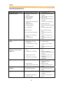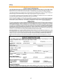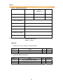
1
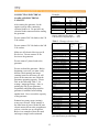
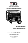
OWNER’S MANUAL
Air-cooled gasoline engine generator set
TG-2500 / TG-3000 / TG-5000
PREFACE
Thank you for purchasing products from EASTERN TOOLS & EQUIPMENT, INC. We
appreciate your business. The following manual is only a guide to assist you and is not a
complete or comprehensive manual of all aspects of maintaining and repairing your
generator. The equipment you have purchased is a complex piece of machinery. We
recommend that that you consult with a dealer if you have doubts or concerns as to your
experience or ability to properly maintain or repair your equipment. You will save time
and the inconvenience of having to go back to the store if you choose to write or call us
concerning missing parts, service questions, operating advice, and/or assembly questions.
Our gasoline generators have some of the following features:
•
•
•
•
•
•
•
•
•
Lightweight construction
Air cooled
Four-stroke gasoline internal combustion engine
Recoil starter
Large fuel tank
Automatic voltage stabilizer
NFB circuit protector
AC and DC outputs
Low oil level sensor
The ETQ air-cooled gasoline generators are widely used when electrical power is scarce.
Our generators provide a portable mobile solution in supplying power for field operations
during project construction.
This manual will explain how to operate and service your generator set.
If you have any questions or suggestions about this manual, please contact your local
dealer or us directly. Consumers should notice that this manual might differ slightly
from the actual product as more improvements are made to our products. Some of the
pictures in this manual may differ slightly from the actual product as well. Eastern
Tools and Equipment, Inc. reserves the right to make changes at any time without
notice and without incurring any obligation.
2
TABLE OF CONTENTS
TECHNICAL SPECIFICATIONS AND DATA
EQUIPMENT DESCRIPTION & KNOWING YOUR GENERATOR
SAFETY PRECAUTIONS
Electric shock and short circuit
Prevention from accidental burns
Refueling precautions
Battery (optional)
Engine safety precautions
Generator safety
PREPARATION BEFORE OPERATION
Engine oil
Air cleaner
Battery (only for electric start models)
GROUNDING THE GENERATOR
OPERATING THE GENERATOR
Starting the engine
Connecting electrical loads and electrical capacity
Stopping the engine
RECEPTACLES
MAINTENANCE
Cleaning the generator
Storage
WIRING DIAGRAMS
PART LISTINGS
Engine
Main components of generator
Fuel tank and system components
Generator head
Generator frame assembly
Electrical panel assembly
TROUBLESHOOTING
LIMITED WARRANTY
PRODUCT REGISTRATION CARD
COMMENT CARD AND APPENDIX
3
Page
4
6
7
7
7
7
8
8
8
9
9
9
10
10
11
11
12
13
13
14
15
15
16
18
18
19
20
21
22
23
24
25
27
28
TECHNICAL SPECIFICATIONS AND DATA
Generator
Technical specifications in SI units
Item
Model
TG-2500
TG-3000
TG-5000
Type
Brushless, revolving magnetic field, self –exciting, 2-pole,
single-phase
Voltage regulator
Capacitor
Frequency (Hz)
60
Rated voltage (V)
Maximum output
(kW)
Rated Output (kW)
Power factor (cos ϕ)
Model
120 / 240
3.0
3.2
6.5
2.7
3.0
5.5
1.0
ETQ168
ETQ200
Unit Set
Gasoline Engine
Engine type
ETQ188
Forced air-cooled, 4-stroke
Displacement (cc)
163
196
389
Max. output
(kW/rpm)
Fuel tank capacity
(L)
Continuous
operating hours
Lube-oil capacity
(L)
Ignition system
4.0 / 3600
4.9 / 3600
2.8 / 3600
12
12
25
7.0
6.8
7.1
.6
.6
1.1
Starting system
Dimensions
(LxWxH) (mm)
Dry weight (kg)
Transistorized ignition (TCI)
Recoil manual start / Electric start (optional)
432x445x597
545x425x440
674x510x530
47
49
83
4
Unit Set
Gasoline Engine
Generator
Technical specifications in English units
Item
Model
TG-2500
TG-3000
TG-5000
Type
Brushless, revolving magnetic field, self –exciting, 2-pole,
single-phase
Voltage regulator
Capacitor
Frequency (Hz)
60
Rated voltage (V)
120 / 240
Maximum output
4.02
4.29
8.71
(HP)
Rated Output (HP)
3.75
4.02
7.37
1.0
Power factor (cos ϕ)
Model
Engine type
Displacement (cu.
in)
Max. output
(HP/rpm)
Fuel tank capacity
(US gal)
Continuous
operating hours
Lube-oil capacity
(oz.)
Ignition system
Starting system
Dimensions
(LxWxH) (in)
Dry weight (lb)
ETQ168
ETQ200
ETQ188
Forced air-cooled, 4-stroke
11.96
23.74
9.95
5.5 / 3600
6.5 / 3600
13 / 3600
3.0
3.17
6.61
7.0
6.8
7.1
20.3
22.3
37.17
Transistorized ignition (TCI)
Recoil manual start / Electric start (optional)
21.46x6.73x17.32 17x17.5x23.5
26.54x20.08x20.87
95
103.6
5
183
EQUIPMENT DESCRIPTION & KNOWING YOUR GENERATOR
Please read this manual and follow the procedures covered in this manual. Become
familiar with the generators functions, applications, and limitations.
Below is a diagram of the locations of the various controls and functions of the generator
WARNING: DO NOT exceed the generator’s wattage / amperage capacity. Our
products are continuously being changed and improved. Every effort has been made to
ensure that information in the manual is accurate and up to date. However, we reserve
the right to change, alter or otherwise improve the product and this manual at any time
without prior notice.
6
ELECTRIC SHOCK AND SHORT
CIRCUIT
SAFETY PRECAUTIONS
In order to ensure safety for the
consumer, please carefully follow
instructions on being careful with the
generators.
Be sure to notify the utility company
when using the generator for backup
power. Use approved transfer
equipment to isolate the generator from
electric utility. In highly conductive
area such as metal decking or steel work,
use a ground circuit fault interrupter.
Never touch the generator if the
generator is wet. Also, never touch the
generator if your hand is wet. Never
operate your generator if the weather
conditions call for any type of
precipitation such as rain, snow, or fog.
Operate the generator ONLY outdoors.
Never run the generator indoors as the
engine gives off poisonous carbon
monoxide, an odorless, and colorless
gas. Inhaling carbon monoxide will
cause nausea, fainting or death. Also,
keep the generator at least 3 feet away
from flammable matter for adequate
ventilation.
PREVENTION FROM ACCIDENTAL
BURNS
Never touch the muffler and its cover
when the engine is running. Never touch
the muffler and cover after the engine
has been used, as the muffler remains
hot for a good period of time.
DANGER
Always properly ground the generator.
Failing to do so can result in
electrocution, particularly if the
generator is equipped with a wheel kit.
REFUELING PRECAUTIONS
Gasoline and its vapors are extremely
flammable. Do not smoke near gasoline
and keep gasoline away from generator
while the generator is running. When
adding fuel, turn the generator off and let
it cool at least 2 minutes before
removing the gas cap. Loosen gas cap
slowly to relieve the pressure in the tank.
Fill fuel tank outdoors and never overfill
the tank.
7
ENGINE SAFETY PRECAUTIONS
Do not touch hot surfaces. Allow
equipment to fully cool down before
touching.
When storing gasoline or equipment
with fuel in tank.
After the generator has been run, the
engine produces heat. The temperatures
of the muffler and nearby areas can
reach or exceed 1600 F. Severe burns
will occur on contact with skin.
Store away from appliances or
equipment that have a pilot light or other
ignition sources because they can ignite
gasoline vapors.
Do not modify the generator in any way.
The generator supplies the rated voltage
and rated frequency at its governed
speed.
GENERATOR SAFETY
BATTERY (optional: for electric start
units only)
Never overload your generator as this
can damage your generator or the
electrical devices connected to it.
Batteries contain electrolyte fluid or
battery acid. Batteries emit hydrogen
gases as battery is being charged. The
slightest spark will ignite hydrogen and
cause and explosion.
Do not start generator with electrical
devices connected to it. Start the
generator first and after the speed of the
generator stabilizes, electrical loads can
be applied to it.
Note: Our units come shipped with a
dry battery for safety shipping purposes.
Dry batteries need to be filled with
electrolytic solution (battery acid) and
fully charged (trickle charged) before
use. During use, the battery level should
be checked once a month to make sure
they are between the high and low
marks.
When connecting electrical loads, make
sure the devices are “OFF” first before
connecting them. Keep the same
concept when disconnecting electrical
devices, make sure all devices are in the
“OFF” position before disconnecting.
Operate the generator on level surfaces
only. Inclined surfaces reduce the
effective lubrication of the engine.
Do not expose the generator to excessive
moisture, dust, dirt, or corrosive vapors.
8
be sure to install the fuel tank cap
on tight after filling.
PREPARATION BEFORE
OPERATION
Before starting the generator, verify the
following conditions.
ENGINE OIL
•
Fill the engine with SAE 10W-30
engine oil for general use or
follow the table below.
•
•
DO NOT overfill the fuel tank.
Always allow room for fuel
expansion.
Never fill the fuel tank when the
engine is running or hot. Allow
the unit to cool for two minutes
before refueling. DO NOT use
light a cigarette or smoke when
filling the fuel tank.
AIR CLEANER
•
•
•
Make sure the generator is on a
level surface and make sure the
oil dipstick is on tight.
•
GASOLINE
•
Unsnap the air cleaner cover
springs, and remove the air
cleaner cover.
Check the air cleaner element to
be sure they are clean and in
good condition.
Add unleaded gasoline and never
fill the fuel tank indoors. Also,
9
If the air filter is dirty, remove
and clean the element.
o Wash in solvent
o Squeeze
o Soak oil
o Squeeze dry
GROUNDING THE
GENERATOR
The National Electric Code requires that
the frame of the generator and the
external electrically conductive parts of
the generator be connected to an
approved earth ground. Local codes
may differ and require other grounding
specifications. For this purpose, please
use the ground wire that attaches from
the frame to the generator unit.
•
Reinstall the air cleaner element
and secure the cover by setting
the cover spring.
BATTERY (only for electric start
models)
Check to make sure that the battery
acid level in each cell is between the
upper and lower limits.
Using a No. 12 AWG (American Wire
Gauge) stranded copper wire to the
frame and to an earth-driven copper or
brass grounding rod provides sufficient
safety against shock. However, local
codes may differ. Contact a local
electrician to find out specifications for
grounding your generator.
(1) Upper limit
(2) Lower limit
Note: Grounding your generator is
highly recommended. It helps prevent
electrical shock if a ground fault
condition exists in the generator or in
faulty connected electrical devices.
Also, because the generator is rotating at
high speeds, static electricity tends to
buildup within the unit. Grounding
helps dissipate the static electricity
buildup often buildup in ungrounded
devices.
10
OPERATING THE
GENERATOR
CAUTION! NEVER start or stop the
unit with electrical loads connected
AND with the connected devices
turned ON.
STARTING THE ENGINE
Before starting the engine, verify that the
engine oil is full, gasoline is full, and air
Filter is in place. Also, disconnect any
load from the AC receptacle, and turn
the AC circuit breaker OFF (Figure 1).
Figure 4. Engine switch on position
Figure 1. Disconnecting electrical devices
•
•
Turn the fuel valve to the “On”
position (Figure 2).
Figure 2. Fuel Valve
•
Pull the recoil starter grip lightly
until resistance is felt, then pull
hard. Warning: Do not allow the
starter grip to snap back against
the engine. Return it gently
(Figure 5.).
Figure 5. Recoil starting rope
Place the choke lever in the
“CHOKE” position (Figure 3.).
Push the choke rod to the “OPEN”
position a short distance at a time over
several seconds as the engine warms up
(Figure 6).
Figure 3. Choke Positions
Figure 6. Putting choke rod to “OPEN”
•
Turn the engine switch to the
“ON” position (Figure 4).
11
Example:
CONNECTING ELECTRICAL
LOADS AND ELECTRICAL
CAPACITY
Tool or Appliance
Air Conditioner
Refrigerator
Freezer
Television
Light (75 Watt)
Total
After starting the generator, let the
engine warm up after connecting
electrical loads to it. Do not have any
electrical loads connected before starting
the generator.
Rated
(Running)
Watts
1200
800
500
500
75
3075 Total
Running Watts
Total Rated (Running) Watts
Highest Additional Surge Watts
Total Generator Output Required
Do not connect 240 Volt loads to the 120
Volt sockets.
Additional
Surge (Starting)
Watts
1800
1600
500
1800 Highest
Surge Watts
= 3075
= 1800
= 4875
Table 1. Wattage reference chart
Tool or Appliance
Do not connect 120 Volt loads to the 240
Volt sockets.
Essentials
Light Bulb – 75 watt
Freezer
Sump Pump
Refrigerator / Freezer – 18
Cu. Ft.
1/3 HP Water Well Pump
Heating/Cooling
Air condition – 10000 BTU
Window Fan
½ HP Furnace Fan Blower
Kitchen
1000 Watt Microwave Oven
Coffee Maker
Single element electric stove
Hot plate
Family Room
DVD / CD Player
VCR
Stereo Receiver
27 “ Color Television
Personal Computer w/17”
monitor
Other
Security system
AM / FM clock radio
½ HP Garage door opener
40 Gallon electric water
heater
DIY / Job Site
Halogen work light
1/3 HP Airless sprayer
Reciprocating Saw
½ HP Electric Drill
7 ¼ “ Circular saw
10” Miter saw
6” Table Planer
10” Table saw / Radial arm
saw
1 ½ HP air compressor
Make sure all electrical devices are 60
Hz devices. Do not connect 50 Hz
devices to the generator.
Do not connect 3-phase loads to the
generator.
Do not overload the generator. Before
beginning your work, you must verify
that the rated (running) and surge
(starting) watts for the items you will
power at the same time are within the
generators operating capacity. Please
refer to the following Table 1. for
wattage / amperage ratings. Also, to
prolong the life of your generator,
sequentially add loads and permit the
generator to stabilize before adding
another load. Never exceed the capacity
of the generator.
Estimate how many surge (starting)
watts you will need. Surge wattage is
the short burst of power needed to start
electric motor-driven tools or appliances
such as a circular saw or refrigerator.
Below is an example of how the rated
and surge wattage can be estimated.
Rated
(Running)
Watts
Additional
Surge
(Starting)
Watts
75
500
800
800
500
1200
1600
1000
2000
1200
300
800
1800
600
1300
1000
1500
1500
2500
-
100
100
450
500
800
-
180
300
480
4000
520
-
1000
600
960
1000
1500
1800
1800
2000
1200
960
1000
1500
1800
1800
2000
2500
2500
Note: wattages listed are only approximates. Check
your electrical device for actual wattage.
12
STOPPING THE ENGINE
•
RECEPTACLES
Turn the AC circuit breaker to the
“OFF” position (Figure 1.).
Figure 1.
This generator is equipped with the
following receptacles:
120 Volt AC, 20 Amp Duplex
Receptacle
Figure 5. 120 Volt, 20 Amp Duplex
Receptacle
•
Unplug all the electrical loads from
the generator panel (Figure 2.).
Figure 2.
•
Let the engine run at no-load for
several minutes to stabilize the
internal temperatures of engine and
generator.
Turn the engine switch to the “OFF”
position (Figure 3.).
Figure 3.
•
•
Figure 6. 240 Volt, NEMA L14-20
Turn the fuel valve to the “OFF”
position (Figure 4.).
Figure 4.
Note: Please be sure to use electrical
cords that support the amount of wattage
being used. The electrical cords should
be able to handle 20 Amps of current at
125 Volts.
13
MAINTENANCE
Below is a routine maintenance schedule.
14
CLEANING THE GENERATOR
•
Generator maintenance consists of
keeping the unit clean and dry. Be sure
to store the unit in a clean and dry
environment, where it will not be
exposed to excessive dust, dirt, moisture
or any corrosive vapors. Cooling slots
should always be clean and free from
clogs.
Drain the fuel from the carburetor
(Figure 2.).
Figure 2.
•
Remove the oil filter cap and drain
plug to drain the oil (Figure 3.).
Figure 3.
•
Tighten the oil drain plug and fill the
engine with new oil to the filter neck
(Figure 4.).
Figure 4.
•
Pull the starter grip carefully until
resistance is felt (Figure 5.).
Figure 5.
•
Store the generator in a clean area.
Note: Do not use a garden hose to clean
the generator. Water can enter the fuel
and intake system and cause problems.
In addition, if water and dirt buildup on
the generators internal windings, the
resistance of these windings will
decrease.
•
•
•
•
To clean the generator, use a damp
cloth to wipe the exterior surfaces.
Use a soft bristle brush to loosen
caked on dirt of oil.
Use a vacuum cleaner to pick up
loose dirt and debris.
Compressed air (not to exceed 25
psi) may be used to blow away dirt.
STORAGE
The generator should be started at least
once every week. If this cannot be done
and you must store the unit more than 30
days, please follow the following
guidelines.
•
Close the fuel valve; drain the fuel
from the fuel tank (Figure 1).
Figure 1.
15
WIRING DIAGRAMS
16
17
Figure 1. Exploded view of engine assembly
PART LISTINGS
Note: Please refer to the engine owner’s manual for a complete listing of parts
18
Figure 2. Main components of generator
Number
Description
Part Number
1
2
Electrical control panel
ETQ 168 Engine
ETQ2500TG1
ETQ2500TG2
3
Muffler
ETQ2500TG3
4
Generator head
ETQ2500TG4
19
Figure 3. Gas tank assembly
Number
1
2
3
4
5
6
7
8
9
10
11
12
13
14
15
Description
Fuel cap
Rubber sealing ring
Filtering cup
Screw
Fuel level gauge
Bolt
Washer
Fuel tank lining
Shock absorber gasket
M6 nut
Fuel tank
Fuel filter
Nut
Fuel valve
Carburetor
20
Part Number
ETQ2500TG5
ETQ2500TG6
ETQ2500TG7
ETQ2500TG8
ETQ2500TG9
ETQ2500TG10
ETQ2500TG11
ETQ2500TG12
ETQ2500TG13
ETQ2500TG14
ETQ2500TG15
ETQ2500TG16
ETQ2500TG17
ETQ2500TG18
ETQ2500TG19
Figure 4. Generator head assembly
Number
1
2
3
4
5
6
7
8
9
10
11
12
13
14
15
Description
Front end cover
Diode
M4 x 8 Bolt
Fan blade
Bearing
Rotor unit
Center bolt
Generator guard sheet
Stator
Assembly bolt
Capacitor
Wiring circuit
M5 x 15 bolt
Stator unit
Dust Cover
21
Part Number
ETQ2500TG20
ETQ2500TG21
ETQ2500TG22
ETQ2500TG23
ETQ2500TG24
ETQ2500TG25
ETQ2500TG26
ETQ2500TG27
ETQ2500TG28
ETQ2500TG29
ETQ2500TG30
ETQ2500TG31
ETQ2500TG32
ETQ2500TG33
ETQ2500TG34
Figure 5. Generator frame assembly
Number
1
2
3
4
5
6
7
8
9
10
11
12
13
14
15
16
17
Description
Complete frame
Capped nut
Spring washer
Flat washer
Motor mount
Flat washer
Spring washer
M10 nut
Wheel
Cotter pin
Wheel spacer
U bolt
M6 lock nut
Axle
Muffler cover
Lock nut
Lock nut
Part Number
ETQ2500TG35
ETQ2500TG36
ETQ2500TG37
ETQ2500TG38
ETQ2500TG39
ETQ2500TG40
ETQ2500TG41
ETQ2500TG42
ETQ2500TG43
ETQ2500TG44
ETQ2500TG45
ETQ2500TG46
ETQ2500T47
ETQ2500TG48
ETQ2500TG49
ETQ2500TG50
ETQ2500TG51
22
Figure 6. Electrical panel assembly
Number
1
2
3
4
5
6
7
8
9
10
11
12
13
14
15
16
17
Description
DC terminal (DC-)
DC terminal (DC+)
Machine screw
Receptacle
Machine screw
Transformer
Voltmeter
On / Off switch
Machine screw
Ground terminal
DC fuse
Receptacle
Nut
Circuit breaker
Nut
Wiring harness
Electric box
23
Part Number
ETQ2500TG52
ETQ2500TG53
ETQ2500TG54
ETQ2500TG55
ETQ2500TG56
ETQ2500TG57
ETQ2500TG58
ETQ2500TG59
ETQ2500TG60
ETQ2500TG61
ETQ2500TG62
ETQ2500TG63
ETQ2500TG64
ETQ2500TG65
ETQ2500TG66
ETQ2500TG67
ETQ2500TG68
TROUBLESHOOTING
Problem
Engine will not start or runs
rough when started
Cause
1. Engine switch set to “OFF”.
2. Fuel valve is in the “Off”
position.
3. Dirty air cleaner.
4. Out of gasoline.
5. Bad gasoline.
6.
7.
8.
Loose or disconnected spark
plug wire.
Bad spark plug.
Water in gasoline.
9.
Overchoking.
10. Low oil level.
11. Excessive rich fuel mixture.
12. Intake valve stuck open or
closed.
13. No compression
7.
8.
9.
3.
4.
Fault in generator.
4.
1.
1.
2.
Electrical short in connected
load.
Generator is overloaded.
3.
Engine speed too low.
3.
4.
Generator circuit shorted.
4.
1.
Load is too high.
1.
2.
3.
Dirty air filter.
Engine needs to be serviced.
2.
3.
Engine shuts down during
operation.
1.
2.
Out of gasoline
Problem with engine
1.
2.
Engine “hunts” or falters.
1.
Choke is opened too soon.
1.
2.
Carburetor is running too
rich or too lean.
2.
Engine runs good but gets
bogged down when loads are
connected.
Engine lacks power.
24
Replace spark plug.
Drain gas tank: fill with fresh
fuel.
Set choke to Run position.
10. Fill crankcase to proper
level.
11. Contact your local service
dealer
12. Contact your local service
dealer.
13. Contact your local service
dealer.
1. Reset circuit breaker.
2. Check and repair.
Circuit breaker open.
Defective cord or poor
connection.
Connected device is faulty.
Engine running but no AC
output.
1.
2.
Solution
1. Set switch to “On”.
2. Turn fuel valve to the “On’
position.
3. Clean or replace air cleaner.
4. Fill fuel tank.
5. Drain gas tank and fill with
fresh fuel
6. Connect wire to spark plug.
3.
2.
Connect a good condition
device.
Contact your local service
dealer.
Disconnect shorted electrical
load.
Refer to “connecting
electrical loads and electrical
capacity”.
Contact your local service
department
Contact your local service
department
See “connecting electrical
loads and electrical
capacity”.
Replace air filter.
Contact your local service
dealer.
Fill fuel tank
Contact your local service
dealer.
Move choke to halfway
position till engine runs
smoothly.
Contact your local service
dealer.
LIMITED WARRANTY
Eastern Tools & Equipment, Inc. will repair or replace, free of charge, any part or parts of the generator that are
defective in material or workmanship or both. Transportation charges on parts submitted for repair or replacement
under this Warranty must be borne by purchaser. This warranty is effective for the time period and subject to the
conditions provided for in this policy. For warranty service, find the nearest Authorized Service Dealer by contacting
the place of purchase or Eastern Tools & Equipment, Inc. THERE IS NO OTHER EXPRESSED WARRANTY.
IMPLIED WARRANTIES, INCLUDING THOSE OF MERCHANTABILITY AND FITNESS FOR A
PARTICULAR PURPOSE, ARE LIMITED TO ONE YEAR FROM PURCHASE, OR TO THE EXTENT
PERMITED BY LAW ANY AND ALL IMPLIED WARRANTIES ARE EXCLUDED. LIABILITY FOR
CONSEQUENTIAL DAMAGES UNDER ANY AND ALL WARRANTIES ARE EXCLUDED TO THE EXTENT
EXCLUSION IS PERMITTED BY LAW. Some states do not allow limitations on how long an implied warranty lasts,
and some states do not allow the exclusion or limitation of incidental or consequential damages, so the above limitation
and exclusion may not apply to you. This warranty gives you specific legal rights and you may also have other rights,
which vary from state to state.
Eastern Tools & Equipment, Inc.
WARRANTY PERIOD***
ENGINES
GASOLINE
GENERATOR
WITHIN U.S.A AND CANADA
CONSUMER
COMMERCIAL
USE
USA
1 year
1 year
or 1000 hours
or 1000 hours
OUTSIDE U.S.A. AND CANADA
CONSUMER
COMMERCIAL
USE
USE
1 year
1 year
or 1000 hours
or 1000 hours
About Your Product Warranty
Eastern Tools & Equipment, Inc. welcomes warranty repair and apologizes to you for being inconvenienced. Any
Authorized Service Dealer may perform warranty repairs. Most warranty repairs are handled routinely, but sometimes
warranty service may be inappropriate. For example, warranty would not apply if an engine is damaged because of
misuse, lack of routine maintenance, shipping, handling, warehousing and improper installation. Similarly, warranty is
void if the serial number on the engine has been removed or if the engine has been altered or modified. If a customer
differs with the decision of the Service Dealer, an investigation will be made to determine whether the warranty
applies. Ask the Service Dealer to submit all supporting facts to his Distributor or the factory for review. If the
distributor or the factory decides that the claim is justified, the customer will be fully reimbursed for those items that
are defective. To avoid misunderstanding, which might occur between the customer and the dealer, listed below are
some of the causes of engine failure that the warranty does not cover.
Normal wear:
Engines and generators, like all mechanical devices, need periodic parts service and replacement to perform well.
Warranty will not cover repair when normal use has exhausted the life of a part of an engine.
25
Improper maintenance:
The life of an engine or your equipment depends upon the conditions under which it operates, and the care it receives.
Some applications, such as tillers, pumps, and rotary movers, are very often used in dusty or dirty conditions, which
can cause what appears to be premature, wear. Such wear, when caused by dirt, dust, spark pug cleaning grit, or other
abrasive material that has entered the engine because of improper maintenance is is not covered by warranty.
26
27
List for comments from users
Date of
Manufacture
Name of user
Model Number
Address of user
Occupation
Place of purchase
Packaging conditions
Operating conditions
Parts Conditions
Malfunction problem
Opinions or suggestions
Note: Please mail the above card to: Eastern Tools & Equipment, Inc.
12220 Rivera Rd, Suite B
Whittier, CA 90606
Appendix:
1. Attached list of tools, fittings, and subassemblies
Order No.
1
2
Name
Air-cooled generator set
Plug
Qty
1
1
Remarks
2. Attached technical documents
Order No.
1
2
3
Name
Air cooled generator manual
Engine instruction manual
Certificate of Quality
28
Qty
1
1
1
Remarks
EASTERN TOOLS & EQUIPMENT, INC.
TEL: 1-626-960-6299
FAX: 1-626-960-6244
WEB SITE.http://easterntools.com
29