1
Portable Intensive Care System
PIC30
User Instruction Manual
Welch Allyn Part Number 991022 – Revision C
Portable Intensive Care System
USER INSTRUCTION MANUAL
Model: PIC 30
Software Revision W
Medical Research Laboratories, Inc.
a Welch Allyn Company
1000 Asbury Drive, Buffalo Grove, Illinois 60089
847/520-0300 (Telephone)
800/462-0777 (Toll-Free)
847/520-0303 (Fax)
www.welchallyn.com (Internet)
©1998, 1999, 2000, 2001, 2002, 2003, 2004
MRL, Inc., a Welch Allyn Company
All rights reserved. Printed in the U.S.A.
Welch Allyn Part Number 991022 - Revision C
Forward / FDA Medical Device Registration
Foreword
This manual is intended to provide information for the proper operation of the
Welch Allyn PIC 30.
DO NOT ATTEMPT TO USE THIS EQUIPMENT WITHOUT THOROUGHLY
READING AND UNDERSTANDING THESE INSTRUCTIONS.
USER'S RESPONSIBILITY
The user is required to be trained in basic monitoring, vital signs assessment, and
emergency cardiac care. As with all other electronic patient care monitors, good clinical
judgment should be used when operating the Welch Allyn PIC. The user should be
completely knowledgeable of the information in the User Instruction Manual.
User must save all shipping containers and packaging materials. When shipping the PIC
System and accessories for calibration, service, or upgrades, the original shipping
containers and packaging materials must be used.
MANUFACTURER'S RESPONSIBILITY
Welch Allyn is responsible for the safety, reliability, and performance of the Welch Allyn
Portable Intensive Care System only if the following three conditions are met:
• Assembly operations, extensions, readjustments, modifications, or repairs are
carried out by persons authorized by Welch Allyn.
• The electrical installation of the relevant room complies with the appropriate
requirements.
• The PIC equipment is used in accordance with the instructions for use.
To ensure patient safety and proper operation, use only Welch Allyn authorized parts
and accessories.
FDA Medical Device Registration
The FDA Safe Medical Device Act stipulates that each end-user is required under
penalty of law to register with the manufacturer all information pertinent to each
medical device.
Please fill out the attached FDA Medical Device Registration postcard and return it
promptly to Welch Allyn. This card must be filled in and returned within 30 days of
product delivery.
If the medical device is transferred from your possession, you must notify Welch Allyn
of the new registration information.
Please contact Welch Allyn (800/462-0777) if you have any questions regarding this
notice.
Welch Allyn PIC30 Operating Instructions
Declaration of Conformity
Declaration of Conformity
Manufacturer:
Medical Research Laboratories, Inc.
a Welch Allyn Company
1000 Asbury Drive
Buffalo Grove, IL 60089
USA
Phone (847) 520-0300
Fax
(847) 520-0303
Welch Allyn Ireland
Navan Business Park
Dublin Road
Navan, Co. Meath
Republic of Ireland
Phone 011-353-466-7775
Fax
011-353-466-7128
declares that the CE-marked product
Product Name: PIC30 (Portable Intensive Care)
Base Units
972039 — PIC30, BIPHASIC, MONOCHROME DISPLAY
973039 — PIC30, BIPHASIC, COLOR DISPLAY
Options
971029 - Charger
971031 - Pacing
971032 - Advisory
Device Type:
Defibrillator / External Transcutaneous Pacemaker / Multifunction Monitor
complies with Council Directive 93/42/EEC (Medical Device Directive) of 14 June 1993
class IIb Annex II
Standards:
General:
ISP 9001
EN 46001
Safety: IEC 601-1 / EN 60601-1
Class I, Continuous operation
Type BF (with external paddles) or
Type CF (with internal paddles)
IEC 601-1-4 / EN 60601-1-4
IEC 601-2-4 / EN 60601-2-4
IEC 601-2-25 / EN 60601-2-25
EN 475
EMC
EC 601-1-2 / EN 60601-1-2
______________________________________
_______________
Huy Doan
Site Quality Manager
Date
Welch Allyn PIC30 Operating Instructions
Table of Contents
Table of Contents
Intended Use . . . . . . . . . . . . . . . . . . . . . . . . . . . . . . . . . . . . . . . . . . . . . . . . i
Warnings, Cautions, and Notices . . . . . . . . . . . . . . . . . . . . . . . . . . . . . . . . i
Definitions of Symbols Used . . . . . . . . . . . . . . . . . . . . . . . . . . . . . . . . . . vii
Chapter 1
General Information. . . . . . . . . . . . . . . . . . . . . . . . . . . . . . . . . . . 1.1
Accessories. . . . . . . . . . . . . . . . . . . . . . . . . . . . . . . . . . . . . . . . . . . . . . . . . . 1.2
Inspection Upon Delivery. . . . . . . . . . . . . . . . . . . . . . . . . . . . . . . . . . . . . . 1.3
General Description . . . . . . . . . . . . . . . . . . . . . . . . . . . . . . . . . . . . . . . . . . 1.4
Safety Features. . . . . . . . . . . . . . . . . . . . . . . . . . . . . . . . . . . . . . . . . . . . . . . 1.4
Equipment Setup. . . . . . . . . . . . . . . . . . . . . . . . . . . . . . . . . . . . . . . . . . . . . 1.5
Loading Recording Paper . . . . . . . . . . . . . . . . . . . . . . . . . . . . . . . . . . . . . . 1.7
Summary of Operations . . . . . . . . . . . . . . . . . . . . . . . . . . . . . . . . . . . . . . . 1.8
Chapter 2
Control Panel and Display . . . . . . . . . . . . . . . . . . . . . . . . . . . . . 2.1
Overview of Interfaces . . . . . . . . . . . . . . . . . . . . . . . . . . . . . . . . . . . . . . . . 2.2
Overview of Controls and Display . . . . . . . . . . . . . . . . . . . . . . . . . . . . . . 2.3
Understanding ECG Monitoring Controls and Display . . . . . . . . . . . . . 2.4
Understanding the Quick Access Buttons and Features . . . . . . . . . . . . . 2.6
Understanding the Defibrillator Controls and Display . . . . . . . . . . . . . . 2.9
Understanding the Pacer Controls and Display (optional) . . . . . . . . . . . 2.11
Understanding the Menu Controls . . . . . . . . . . . . . . . . . . . . . . . . . . . . . . 2.13
Chapter 3
Program Menu Setup . . . . . . . . . . . . . . . . . . . . . . . . . . . . . . . . . . 3.1
Basic Menu Structure . . . . . . . . . . . . . . . . . . . . . . . . . . . . . . . . . . . . . . . . . 3.2
PIC30 Menu – Heart Rate Alarm . . . . . . . . . . . . . . . . . . . . . . . . . . . . . . . . 3.3
PIC30 Menu – Log Menu, Sample, and Bright Functions . . . . . . . . . . . . 3.5
Setup Menu – ECG Configuration Menus . . . . . . . . . . . . . . . . . . . . . . . . 3.6
Setup Menu – Grid, Time, Date, and Supervisor Code Menus . . . . . . . . 3.8
Overview of Supervisor Menus . . . . . . . . . . . . . . . . . . . . . . . . . . . . . . . . . 3.10
Supervisor – Defibrillator Menu . . . . . . . . . . . . . . . . . . . . . . . . . . . . . . . . 3.11
Supervisor – Pacer Menu (optional) . . . . . . . . . . . . . . . . . . . . . . . . . . . . . 3.12
Supervisor – Diag Menu. . . . . . . . . . . . . . . . . . . . . . . . . . . . . . . . . . . . . . . 3.13
Supervisor – Setup Menu . . . . . . . . . . . . . . . . . . . . . . . . . . . . . . . . . . . . . . 3.14
Supervisor – Upgrade Menu . . . . . . . . . . . . . . . . . . . . . . . . . . . . . . . . . . . 3.16
Chapter 4
Patient Preparation . . . . . . . . . . . . . . . . . . . . . . . . . . . . . . . . . . 4.1
Preparing Patients for ECGs. . . . . . . . . . . . . . . . . . . . . . . . . . . . . . . . . . . . 4.2
Applying ECG Sensors . . . . . . . . . . . . . . . . . . . . . . . . . . . . . . . . . . . . . . . . 4.3
Using Disposable ECG Sensors . . . . . . . . . . . . . . . . . . . . . . . . . . . . . . . . . 4.3
Chapter 5
ECG Monitoring . . . . . . . . . . . . . . . . . . . . . . . . . . . . . . . . . . . . . 5.1
Monitoring with Defibrillator Paddles . . . . . . . . . . . . . . . . . . . . . . . . . . . 5.2
Monitoring with 3-Lead Patient Cable . . . . . . . . . . . . . . . . . . . . . . . . . . . 5.2
Monitoring with 5-Lead Patient Cable . . . . . . . . . . . . . . . . . . . . . . . . . . . 5.3
Monitoring with “Hands-Free” Defibrillation Pads (optional) . . . . . . . . 5.4
Welch Allyn PIC30 Operating Instructions
Table of Contents
Chapter 6
Defibrillation . . . . . . . . . . . . . . . . . . . . . . . . . . . . . . . . . . . . . . . . 6.1
Defibrillation with External Paddles . . . . . . . . . . . . . . . . . . . . . . . . . . . . . 6.2
Defibrillation with Pediatric Adapter . . . . . . . . . . . . . . . . . . . . . . . . . . . . 6.3
Defibrillation with Multipurpose Hands-Free Pads (optional) . . . . . . . . 6.4
Performing Synchronized Cardioversion . . . . . . . . . . . . . . . . . . . . . . . . . 6.5
Chapter 7
External Pacing. . . . . . . . . . . . . . . . . . . . . . . . . . . . . . . . . . . . . . . 7.1
External Pacer Operation Procedures (optional) . . . . . . . . . . . . . . . . . . . 7.2
Chapter 8
Event Documentation. . . . . . . . . . . . . . . . . . . . . . . . . . . . . . . . . . 8.1
Chart Recorder Startup Printout . . . . . . . . . . . . . . . . . . . . . . . . . . . . . . . . 8.2
Turning On/Off the Chart Recorder . . . . . . . . . . . . . . . . . . . . . . . . . . . . . 8.3
Automatic Printing . . . . . . . . . . . . . . . . . . . . . . . . . . . . . . . . . . . . . . . . . . . 8.4
Event Log Summary . . . . . . . . . . . . . . . . . . . . . . . . . . . . . . . . . . . . . . . . . . 8.5
Chapter 9
Power Source . . . . . . . . . . . . . . . . . . . . . . . . . . . . . . . . . . . . . . . . 9.1
General Precautions . . . . . . . . . . . . . . . . . . . . . . . . . . . . . . . . . . . . . . . . . . 9.2
PIC30 Power Supply/Paddle Holder (optional) . . . . . . . . . . . . . . . . . . . 9.2
Battery Operation and Maintenance . . . . . . . . . . . . . . . . . . . . . . . . . . . . . 9.3
Chapter 10
Troubleshooting . . . . . . . . . . . . . . . . . . . . . . . . . . . . . . . . . . . . . 10.1
Troubleshooting Basic Unit Problems . . . . . . . . . . . . . . . . . . . . . . . . . . . 10.2
Troubleshooting Trace Problems . . . . . . . . . . . . . . . . . . . . . . . . . . . . . . . 10.3
Recognizing and Reducing ECG Artifact . . . . . . . . . . . . . . . . . . . . . . . . 10.4
Chapter 11
Maintenance and Service . . . . . . . . . . . . . . . . . . . . . . . . . . . . . . 11.1
Testing Equipment. . . . . . . . . . . . . . . . . . . . . . . . . . . . . . . . . . . . . . . . . . . 11.2
Inspecting for Damage . . . . . . . . . . . . . . . . . . . . . . . . . . . . . . . . . . . . . . . 11.4
Functional Tests . . . . . . . . . . . . . . . . . . . . . . . . . . . . . . . . . . . . . . . . . . . . . 11.5
Cleaning and Disinfecting the PIC30 . . . . . . . . . . . . . . . . . . . . . . . . . . . . 11.9
Chapter 12
Specifications . . . . . . . . . . . . . . . . . . . . . . . . . . . . . . . . . . . . . . . 12.1
Welch Allyn PIC30 Operating Instructions
Intended Use / Warnings, Cautions, and Notices
Intended Use
The Welch Allyn PIC30 is intended for ECG monitoring, defibrillation, and transthoracic
external pacing and can be use by trained, authorized medical personnel who are
familiar with basic monitoring, vital signs assessment, and emergency cardiac care. The
PIC30 is also intended for use by physicians at the scene of an emergency or in a
hospital emergency room.
Federal (USA) law restricts this device to use by or on the order of a physician.
It is highly recommended that any person using the PIC30 should have been trained in
CPR or be ACLS certified, and be completely knowledgeable of the information in this
manual.
Warnings, Cautions, and Notices
WARNINGS
WARNING: If conductive gel forms a continuous path between the defibrillator
electrodes, delivered energy to the heart muscle may be dramatically reduced, resulting
in ineffective defibrillation. In this case, remove the gel by wiping the surface of the
body and reposition the electrodes, to eliminate the shunting path before attempting
additional shocks.
WARNING: The PIC30 can deliver 360 joules of electrical energy. If proper
defibrillation protocol is not followed as described in this manual, the electrical energy
could cause personal injury or death to the operator or a bystander.
WARNING: During defibrillation discharge, the operator and all other people must not
contact the patient, the bed or any other conductive surfaces that are in contact with the
patient. The electrical energy delivered to the patient could also be shunted to any other
person who is in contact with the patient or the conductive surface.
WARNING: Do not use the defibrillator in the presence of oxygen sources (such as
bag-valve-mask devices or ventilators), flammable gases or anesthetics. These
environments can produce fire or explosion hazards. Remove all oxygen sources from
the patient vicinity before discharge.
WARNING: Electrical shock hazard. DO NOT contact the patient during defibrillation.
Otherwise, serious injury or death could result.
WARNING: NEVER position defibrillator paddles very close to or over ECG sensors
or jewelry. Severe burns may result from improper placement of defibrillator paddles
against the body surface.
WARNING: Hazardous voltage. To reduce the risk of electrical shock, DO NOT
attempt to remove the cover of the PIC30 under any circumstances. Refer servicing to a
qualified technician.
WARNING: If safety procedures are not performed, increased risk to patient, operator
and device can occur.
WARNING: Shock hazard. Use of accessories, other than those specified in these
operating instructions, or additional equipment attached to the patient may adversely
affect safe levels of patient leakage currents.
Welch Allyn PIC30 Operating Instructions
i
Warnings, Cautions and Notices
WARNING: Defibrillator paddles should be kept clean and dry when not in use.
When preparing electrodes and during defibrillation procedures, extreme care should be
exercised to prevent gel or any conductive material from forming a pathway between
the operator and metal electrodes of the paddles. Do not allow gel or any other
conductive material to form an electrical bridge between the defibrillator electrodes or
to the monitoring electrodes. Electrical arcing and/or patient burns could occur during
defibrillation. Arcing and patient burns could prevent sufficient defibrillation energy
from being delivered to the patient.
GENERAL CAUTIONS
ACCESSORIES
Use only authorized accessories (listed on page 1.2 of this manual). Use of unauthorized
accessories may cause the device to operate improperly and provide false measurements.
STERILIZATION
Do not attempt to sterilize any accessory or any equipment part.
BATTERY CARE
Proper care and maintenance of the batteries is important to insure continuous
operation during portable use of the PIC30. If the batteries are not maintained properly,
loss of power during portable use could result, affecting patient care.
DROPPED OR DAMAGED
If this device has been dropped or damaged in any way, refer the device to qualified
service personnel for verification of performance and/or servicing.
INGRESS OF LIQUIDS
To achieve the specified level of protection against spilled or splashed liquids,
thoroughly dry all exposed surfaces of this device prior to operation or connection to
mains power.
DISPOSABLE ELECTRODES
When obtaining a new supply of disposable electrodes for monitoring, defibrillation or
pacing, verify that they will properly connect to the existing cables prior to putting in
service. Do not use these electrodes if gel is dry. Always verify expiration dates on dated
items such as disposable defibrillation or pacing pads, monitoring electrodes and
battery packs. If the expiration date has passed, replace the disposable items
immediately.
FERROMAGNETIC EQUIPMENT
Biomedical equipment and accessories, such as ECG electrodes and cables contain
ferromagnetic materials. Ferromagnetic equipment must not be used in the presence of
high magnetic fields created by magnetic resonance imaging (MRI) equipment. The
large magnetic fields generated by an MRI device can move ferromagnetic equipment
with an extremely violent force, which could cause serious personal injury or death to
persons between the equipment and the MRI device.
LABELS
Observe all CAUTION and WARNING labels on the equipment and accessories.
PATIENT OR OPERATOR PHYSICAL HARM
Place the PIC30 System, accessories and cables in a position where they cannot harm the
patient should they fall. Keep all cables away from the patient’s neck and feet to
prevent entanglement.
ii
Welch Allyn PIC30 Operating Instructions
Warnings, Cautions and Notices
PERFORMANCE
The PIC30 may not meet performance specifications if stored, transported or used
outside the specified storage or operating environmental range limits.
EVENT LOG SUMMARY
To prevent incorrect trending data from being printed, clear the Log from the Log menu
prior to use on a new patient.
MONITORING CAUTIONS
CAUTION: Use only PIC30 patient cables. Other cables can produce excessive artifact,
causing an inability to interpret the ECG.
CAUTION: Use only ECG electrodes that meet the AAMI standard for electrode
performance (AAMI EC-12). Use of electrodes not meeting this AAMI standard could
cause the ECG trace recovery after defibrillation to be significantly delayed.
CAUTION: The type of surface ECG electrodes and the technique used in applying the
electrodes are major factors in determining the quality of the signal obtained. Use highquality, silver-silver chloride electrodes. These electrodes are designed to provide
excellent baseline stability, and rapid recovery from defibrillation, and minimize
artifacts from patient movement. Do not use electrodes if gel is dry.
CAUTION: When attempting to interpret subtle ECG changes (ST segments, etc.), use
only the diagnostic frequency response mode. Other frequency response settings may
cause misinterpretation of the patient’s ECG. See Frequency Response section on
page 3.6 for further details.
CAUTION: Excessive artifact can be the result of improper skin preparation of the
electrode sites. Follow skin preparation instructions on page 4.2.
CAUTION: Do not operate the PIC30 in conjunction with electrocautery or diathermy
equipment. Such equipment, as well as equipment that emits strong radio frequency
signals, can cause electrical interference and distort the ECG signal displayed by the
monitor, thereby preventing accurate interpretation of the rhythm.
CAUTION: Do not operate the PIC30 in close proximity to any other monitor with
respiration measurements. The two devices could affect the respiration accuracy.
CAUTION: The following caution is in accordance with the disclosure requirement of
AAMI Standard EC13-1992 section 3.1.2.1m: Certain line-isolation monitors may cause
interference on the ECG display and may inhibit heart rate alarms.
Note: This caution is an AAMI requirement that applies to all ECG monitors,
regardless of make or model.
CAUTION: Do not use the auto gain setting for diagnosing asystole.
CAUTION: Conductive parts of electrodes and conductors, for applied parts, should
not contact other conductive parts including earth. (IEC 601-2-27).
Welch Allyn PIC30 Operating Instructions
iii
Warnings, Cautions and Notices
DEFIBRILLATION CAUTIONS
CAUTION: After a synchronized cardioversion, the SYNC mode can be configured to
be cleared after each shock or disarm. The user may have to reselect (press) the SYNC
switch after each synchronized cardioversion shock performed on a patient. The PIC30
can be configured in the Supervisor-Defibrillation Set-up menu to remain in the SYNC
mode after each synchronized cardioversion.
CAUTION: Synchronized cardioversion can be performed in the paddle monitoring
mode. However, it is possible that artifact can be produced by the moving paddles,
which could cause the defibrillator to trigger on the artifact. It is recommended that
monitoring in leads I, II or III be used during synchronized cardioversion. Paddle
monitoring should not be used for elective cardioversion procedures.
CAUTION: To avoid damage to the defibrillator or the tester, never attempt to
repeatedly charge and discharge the defibrillator in rapid succession. If a need for
repetitive testing arises, allow a waiting period of at least 1 minute for every third discharge.
CAUTION: Monitoring ECG through the paddles may result in inaccurate heart rate
display due to artifact.
CAUTION: In the SYNC mode the defibrillator will not discharge without a command
(R-Wave) signal indicated by a SYNC marker, flashing SYNC indicator and an audible
beep if the R-wave beeper is enabled.
CAUTION: Do not use the defibrillator if excessive condensation is visible on the device.
CAUTION: Use only Welch Allyn approved disposable defibrillation and pacing pads
and cables. Ineffective pacing or defibrillation may result.
CAUTION: Improper defibrillation technique can cause skin burns. To limit possible
skin burns, use only approved defibrillation gel on paddles, insure that the gel covers
the entire paddle surface and press firmly against patient’s bare chest (no electrodes or
foreign objects underneath the paddles).
CAUTION: Disposable defibrillation electrodes must be used in accordance with the
manufacturer’s instructions. Do not use expired, dry electrodes or reuse disposable
electrodes, as improper patient contact may result in patient burns and inability of the
device to function properly and/or ineffective defibrillation..
CAUTION: The device contains an automatic disarm of the stored energy. If the
operator has not delivered the energy to a patient or test load, an internal timer will
disarm the stored energy 1 minute after the charge ready signal occurs. The charge
ready signal is indicated by a continuous audible tone and the energy availability graph
displayed on the monitor. The unit will indicate disarm activate with change in pitch
10 seconds prior to disarm
CAUTION: If a new energy level is selected after the charge button is pushed and while
the defibrillator is charging, defibrillator will automatically charge to the new energy
selection. The CHARGE button need not be pressed again to select the new energy level.
CAUTION: Any medical electronic device that is not labeled “defibrillation
protected”must be disconnected from the patient. Otherwise damage or patient injury
may occur.
CAUTION: Some erythema of the skin and/or minor burns may occur during
defibrillation. Use proper defibrillation techniques, as outlined in this operating
instruction manual, to minimize erythema/burns.
iv
Welch Allyn PIC30 Operating Instructions
Warnings, Cautions and Notices
CAUTION: Decision to shock must be made by qualified medical personnel trained in
CPR and advanced cardiac life support.
PACER CAUTIONS (OPTIONAL FEATURE)
CAUTION: Defibrillation will take priority over external pacing. Should the
defibrillator be charged during the administration of external pacing, the pacer will
automatically be turned off and the defibrillator will charge to the selected energy.
CAUTION: Transcutaneous pacing should not be used to treat V FIB (ventricular
fibrillation). In cases of V FIB, immediate defibrillation is advised.
CAUTION: Transcutaneous pacing may cause discomfort ranging from mild to severe,
depending on the patient’s tolerance level, muscle contractions and electrode placement.
In certain cases, discomfort may be decreased by slightly relocating the pacing pads.
CAUTION: It is important to monitor the patient closely to verify that both mechanical
and electrical capture are occurring. Electrical capture can be verified by observing the
presence of a large ectopic beat after the pacing pulse is delivered. The size and
morphology of the beat are dependent on the patient. In some instances the beat may
appear as a relatively normal looking QRS pulse. Mechanical capture can be verified by
checking for signs of increased blood flow i.e., reddening of the skin, palpable pulses,
increased blood pressure, etc. Continuously observe the patient during pacing
administration to insure capture retention. Do not leave the patient unattended when
administering external pacing therapy.
CAUTION: Some erythema of the skin and/or minor burns may occur under the
pacing electrodes in some patients. For prolonged periods of pacing (>4 hours),
periodically inspecting the skin beneath the electrodes (when patient’s condition allows)
is recommended. Evaluate the patient’s condition and if the skin is degrading
discontinue external pacing if it is not required, repositioning is not possible and/or
another form of pacing is available.
CAUTION: Disposable defibrillation/pacing electrodes must be used in accordance
with the manufacturer’s instructions. Do not use expired, dry electrodes or reuse
disposable electrodes, as improper patient contact may result in patient burns,
ineffective pacing and inability of the device to function properly.
CAUTION: The pacing rate determination can be adversely affected by artifact. If the
patient’s pulse and the heart rate display are significantly different, external pacing
pulses may not be delivered when required. Ensure good ECG electrode contact.
CAUTION: Artifact and ECG noise can make R-wave detection unreliable, affecting the
HR meter and the demand mode pacing rate. Always observe the patient closely
during pacing operations. Consider using asynchronous pacing mode if a reliable ECG
trace is unobtainable.
ADVISORY CAUTIONS (OPTIONAL FEATURE)
CAUTION: Cardiac Pacemakers. The presence of an internal cardiac pacemaker may
adversely affect analysis results. If it is known, or suspected, that the patient is fitted
with a cardiac pacemaker, follow your own locally-established procedure for dealing
with defibrillation of such patients.
CAUTION: The Advisory mode should only be utilized on victims of cardiac arrest
who exhibit unconsciousness, absence of breathing, and absence of pulse.
Welch Allyn PIC30 Operating Instructions
v
Warnings, Cautions and Notices
CAUTION: Excessive motion may affect analysis results. ECG analysis should not be
performed when the patient is being moved. Stop all patient movement and do not
touch patient when the ECG analysis is in process. Take precautions to eliminate sources
of motion or artifact before using the Advisory feature.
BATTERY CAUTIONS
CAUTION: Battery is shipped discharged. Charge fully before use. Charge time to 100%
is approximately 4 hours.
CAUTION: Use only Welch Allyn batteries in the PIC30. Use of any other battery can
damage the PIC30 and/or not provide sufficient power, inhibiting patient care.
CAUTION: Due to the critical dependency on batteries, replacement of the battery is
recommended at 24-month intervals due to self degradation of the battery chemistry.
Periodic maintenance and testing is highly recommended to ensure proper battery
performance.
POWER SOURCE AND INTERNAL PIC30 DEFIB TESTER (OPTIONAL)
CAUTION: When testing the defibrillator, ensure that the paddle surface is positioned
properly in the paddle holder test well. Do not use gel during this test. When
discharging the paddles into the tester, press the paddles firmly onto the test points to
prevent pitting the paddle surfaces.
CAUTION: Do not take the paddle holder apart or attempt to repair it yourself.
CAUTION: The power source should not be used in the presence of flammable
anesthetics or materials.
NOTICES
NOTICE: A battery is not mandatory for operation of the PIC30. The PIC30 will operate
from an optional AC power source alone. Some defibrillation charging times will
increase with no battery installed.
NOTICE: Do not place a used battery pack in your regular trash. The incineration, land
filling, or mixing of NiCad batteries with municipal waste is PROHIBITED BY LAW in
most areas. Return this battery pack to a government-approved battery recycler. Contact
your local waste management officials for more information.
NOTICE: U.S. Federal law restricts this device to use by or on the order of a physician.
NOTICE: If the battery pack is removed for any reason, labeling of the PIC30 is
required indicating out-of-service for battery operation.
vi
Welch Allyn PIC30 Operating Instructions
Definitions of Symbols Used
Definitions of Symbols Used
SAFETY SYMBOLS
Graphical symbols, letter symbols and signs listed below may be found on the PIC30
and accessories. Please note the use of these symbols for safe and proper use of the
equipment.
Alternating current
Negative input terminal
Attention, consult
accompanying documents
Positive input terminal
Auxiliary power operation
Power off
Caution, high voltage
Power on
Dangerous voltage
Recycle battery
Defibrillator protected,
type BF patient connection
Protective earth (ground)
Defibrillator protected,
type CF patient connection
Defibrillator
discharge button
Earth (ground)
Release
CERTIFICATION SYMBOLS
0197
This symbol on the device indicates that the device meets the
requirements of Council Directive 93/42/EEC, MDD, Class IIb.
This symbol on the device indicates that the device meets the
requirements of Council Directive 93/42/EEC, MDD, Class I.
Underwriters Laboratories Listed Device UL 544
Canadian Underwriters Laboratories Listed Device
Welch Allyn PIC30 Operating Instructions
vii
Definitions of Symbols Used
DISPLAY SYMBOLS
Graphical and text icons listed below may be found on the display of the PIC30 during
operation.
Alarm off
Auto heart rate undetermined
Alarm on
Internal log gauge
Alarm lower limit set
Mute
Alarm upper limit set
QRS beeper off
Automatic HR Alarm set
QRS beeper on
Alarm - push to disable
Volume level
Battery full
Supervisor menu locked
Battery low warning
Supervisor menu unlock
Battery (partially depleted)
N
Calibration pulse
Check chart recorder
viii
Welch Allyn PIC30 Operating Instructions
Notch filter On
Brightness
A
Advisory (Optional)
Chapter
1
General Information
Congratulations on your purchase of a top quality Welch Allyn PIC30 defibrillator.
Your business is important to us. If you would like more information or if you have any
questions, contact your local representative or call Welch Allyn, Inc. Technical Service
Department at (800) 462-0777 or (847) 520-0300.
CAUTION: Federal law restricts this device to use by or on the order of a physician.
Accessories. . . . . . . . . . . . . . . . . . . . . . . . . . . . . . . . . . . . . . . . . . . . . . . . . . 1.2
Inspection Upon Delivery. . . . . . . . . . . . . . . . . . . . . . . . . . . . . . . . . . . . . . 1.3
General Description . . . . . . . . . . . . . . . . . . . . . . . . . . . . . . . . . . . . . . . . . . 1.4
Safety Features. . . . . . . . . . . . . . . . . . . . . . . . . . . . . . . . . . . . . . . . . . . . . . . 1.4
Equipment Setup. . . . . . . . . . . . . . . . . . . . . . . . . . . . . . . . . . . . . . . . . . . . . 1.5
Loading Recording Paper . . . . . . . . . . . . . . . . . . . . . . . . . . . . . . . . . . . . . . 1.7
Summary of Operations . . . . . . . . . . . . . . . . . . . . . . . . . . . . . . . . . . . . . . . 1.8
Welch Allyn PIC30 Operating Instruction
1.1
General Information
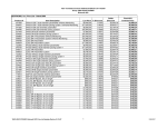
Accessories
INCLUDED
Part No.
Description
001790
3-lead patient cable (AHA)
001647
Super Pac
001725
ECG electrodes
002051
Defibrillator gel (1 tube)
800576
Power cord (country dependent)
001741
ECG chart paper
991022
Operating manual
971106
Standard paddle set
001853
Defibrillation pads, adult
OPTIONAL
Part No.
1.2
Description
971107
Pacing and hands-free adapter
971125
Internal paddle adapter
570310
Internal paddle cable
001517
Internal paddle electrode, adult (set)
001516
Internal paddle electrode, pediatric (set)
001537
Pediatric paddle adapters (set)
980139
3LD Simulator
001795
5 - lead AHA patient cables
001796
5 - lead IEC patient cables
001794
3 - lead IEC patient cables
971108
Deluxe paddle set
971032
Field upgrade, advisory option
971031
Field upgrade, pacer option
001788
Multipurpose electrodes, adult
001781
Multipurpose electrodes, pediatric
001720
Bitrode limb electrodes
002052
KLEAN TRACETM conductive spray
971029
Paddle tray/charger
001638
SmartPak Plus battery
971104
Quick Charger
Welch Allyn PIC30 Operating Instructions
General Information
Inspection Upon Delivery
Your new PIC30 was carefully inspected before shipment. Inspect your unit upon
delivery for any damage which may have occurred in transit. If you notice any damage,
please contact your shipping agent.
If items are missing, contact your local representative or call Welch Allyn, Inc. Technical
Service Department at (800) 462-0777 or (847) 520-0300. To determine the initial
installation condition of the PIC30 after shipment, follow the simple steps below:
1. Open and carefully unpack each carton.
2. Examine the instrument and accessories for signs of damage.
3. Check the packing list to determine that all accessories have been received.
Save all packing materials, invoicing, and any other paperwork in case discrepancies occur.
Power switch
Connect defibrillator paddles or
optional hands-free adapter by
sliding connector on here.
Insert battery on right side of
PIC30.
DETERMINE SOFTWARE SETUP
In order to ensure that the device is running properly after shipping and the proper
features are installed, follow the instructions below:
1. Connect defibrillator paddles or the multipurpose hands-free adapter.
2. Plug the AC power cord into the PIC30 and into a power outlet.
3. Insert a PIC30 battery into the battery slot and charge battery.
4. Press the PIC30 power switch to ON.
5. The PIC30 will perform a series of self-tests and a “Self-Test Passed” message will be
printed on the chart recorder paper.
6. Installed features will appear on the display after the self-tests have been completed.
Standard features are ECG monitor and defibrillator. Optional features are pacer and
advisory function.
If you note any discrepancies, please contact Welch Allyn with your model and serial
number.
ADVISORY OPTION
The PIC30 is available with an advisory ECG analysis option. This option is an effective
way of acquiring a second opinion of a patient’s ECG condition within seconds.
Developed by Medical Research Laboratories, the Advisory option analyzes a patient’s
ECG and displays a “Shock Advised” or “No Shock Advised” prompt within
4 - 16 seconds.
Welch Allyn PIC30 Operating Instructions
1.3
General Information
General Description
FLEXIBLE DESIGN
The PIC30 has been designed to allow additional options to be installed anytime in the
future. This system can grow with your needs.
SMALL, LIGHTWEIGHT
Weighing only 13.5 lb (6 kg), excluding battery, and not much larger than a cardiac
monitor, this full-function intensive care tool is ideal for transport/portable applications.
LARGE, 6.4" (16.2 CM) BRIGHT LCD DISPLAY
A large, bright display allows viewing the critical parameters from significant distance.
Safety Features
WARNING: Electrical shock hazard. DO NOT contact paddle electrodes or
patient during defibrillation. Otherwise, serious injury or death could result.
WARNING: NEVER position defibrillator paddles very close to or over ECG
electrodes. Severe burns may result from improper contact of defibrillator
paddles. Before using defibrillator, consult these operating instructions for
proper procedures.
Includes electrically isolated patient inputs. This conforms to IEC and AAMI/ANSI
requirements.
This symbol next to the patient cable connector indicates this equipment is classified as
defibrillation-protected, Type CF equipment. The patient cable and input circuits are
designed to prevent damage if the unit is connected to a patient during defibrillation.
1.4
Welch Allyn PIC30 Operating Instructions
General Information
Equipment Setup
Note: The battery that is shipped with your new PIC30 is not charged. To charge the
battery and prepare the PIC30 for normal use, follow the instructions below.
INSERTING THE BATTERY INTO THE PIC30
To insert the battery, locate the battery slot on the right side of the PIC30 and slide the
battery in, connectors first. Press the battery firmly back into the slot to assure proper
connection of all 4 contact points on the battery.
CHARGING A BATTERY
If paddle holder/charger is installed, plug the unit's AC power cord into a wall outlet
and insert battery into the PIC30. Otherwise insert the battery into the quick charger.
The yellow “charger” indicator will illuminate, indicating that the battery is being
charged. This light will remain on for the duration of the charging cycle. When the
battery is fully charged, the yellow light will flash to indicate that it is ready for use.
CONNECTING THE PATIENT CABLE
Make sure the connector on the cable is firmly pushed into the patient connector
interface.
CONNECTING THE DEFIBRILLATOR ADAPTER
Slide the adapter inward along the guide plate on the defibrillator interface. Make sure
the adapter is pushed snug against the plastic housing to assure a solid connection.
STANDARD ADULT PADDLES
Sternum Paddle
Discharge button
Apex Paddle
Discharge button
Defibrillator Adapter
Defibrillator adapter release button
DELUXE ADULT PADDLES (optional)
Sternum Paddle
Discharge button
Apex Paddle
Discharge button
Note: When sliding the defibrillator adapter
on, make sure the release button clicks into
place and returns to its up position.
(a)
(b)
Energy selection button
Charge button
Pressing (a) will increase energy selection. Pressing (b) will decrease energy selection.
Welch Allyn PIC30 Operating Instructions
1.5
General Information
Multipurpose Hands-Free Adapter and Electrodes (optional)
1. Multipurpose Pads
2. Pad Connector
Connects to patient connector.
Hands-Free
1
3. Patient Connector
Accepts disposable monitoring / defibrillation /noninvasive pacing pads.
4. Multipurpose Hands-Free Adapter
5. Hands-Free Discharge Button
6. Adapter Release Button
Unlocks the adapter connector from the defibrillator to
allow removal.
2
Note: When sliding the multipurpose hands-free
adapter on make sure the release button clicks
into place and returns to its up position.
3
6
5
4
TURNING THE UNIT ON AND OFF
Press the
switch on the PIC30. The unit performs a
self-test and prints out the strip. To power off the unit press
the
switch on the PIC30.
Name:
SYSTEM ON
01/06/97
12:05:44
SN: xxxx
SW Rev: xx
Test Strip
1.6
Welch Allyn PIC30 Operating Instructions
General Information
Loading Recording Paper
The check recorder icon (
) will appear in the message window of the display when
the chart paper is empty or the chart recorder door is not closed properly.
Swing-door
Release lever
Free end of
paper on top
Roll in chart recorder
with swing-door closed
When inserting the
paper roll, the free
end should be over
the top of the roll.
Note: The low paper indicator is signified by a black or red strip at the top of the
chart recorder paper. When the indicator appears, approximately 8 ft (2.4 m) of
paper is left on the roll.
Note: USE only Welch Allyn approved paper.
1. Open the door by pushing on the release lever located on the side of the chart
recorder.
2. Remove the empty spool core. Place the new roll of ECG paper with the free end of
the paper on top of the roll. Insert the new spool until it snaps onto the spool
retaining arms. The spool should be positioned so the inside or shiny side of the
paper contacts the thermal array print head. The spool should feed paper from the
top.
3. Pull out approximately 2"-3" (5-7 cm) of paper and bring the free end of the paper
around to the front of the swing-out door; then completely close the door.
4. With the power switch on, press the P r i n t button and allow the paper to feed
through the roller automatically. Press P r i n t again to stop paper feed.
Note: If
icon flashes on the display, the paper is probably not moving freely
through the slot in the door or the door is not completely shut. Open the door and
make sure the paper moves freely through the slot after closing the door again.
If the chart recorder runs, but nothing is printed, the paper is in backwards. Rotate the
spool so the inside of the paper contacts the print head.
Welch Allyn PIC30 Operating Instructions
1.7
General Information
Summary of Operations
CAUTION: The Summary of Operations should be used as a reference only by those
who have already read the User Instruction Manual. Please read the User
Instruction Manual completely before using the PIC30.
SYSTEM SET-UP
1.
2.
3.
4.
5.
6.
Press
switch to OFF.
Connect appropriate options and accessory equipment.
Install charged battery or axillary AC power source.
Press
switch to ON.
Clear log if the log gauge indicates a previous patient's events are in the log.
Verify that the configuration menus are set appropriately.
ECG MONITORING
1.
2.
3.
4.
Connect ECG patient cable, multipurpose hands-free adapter or paddles
to the PIC30 System.
Prep patient's skin and connect electrodes to patient.
Select appropriate
.
Adjust
as necessary.
DEFIBRILLATING
1.
2.
3.
4.
5.
6
7.
Monitor patient's ECG on the display using the patient cable, multipurpose
hands-free adapter or paddles.
Apply gel to paddles or apply Multipurpose electrodes to patient.
Select energy by pressing the
up/down buttons.
Press
button on front panel or on apex paddle (deluxe paddles).
After the defibrillator charges to the selected energy (a continuous charge
tone will be heard and the selected energy will be highlighted on the energy
bar graph), visually and verbally clear the patient area.
Place the paddles firmly on the patient's chest at apex and sternum.
To discharge the defibrillator, press both
buttons on the paddles or
press the
button on the multipurpose hands-free adapter .
PACING (NON-INVASIVE PACING) – OPTIONAL
1.
2.
3.
4.
5.
6.
7.
8.
1.8
Monitor patient's ECG using the ECG patient cable and display.
Set lead to I, II or III.
Apply multipurpose pads to patient as illustrated on the package.
Connect multipurpose pads to multipurpose hands-free adapter .
Press pacer Pacer button to turn on pacer.
Press pacer
button to select either DEMAND or ASYNC modes.
Press pacer
button to select the desired rate.
Press pacer
button to initiate pacing.
Press pacer
up arrow to increase the pacing output current, until capture is
obtained. Note: If the defibrillator is charged, the pacer will automatically turn off.
Welch Allyn PIC30 Operating Instructions
Chapter
2
Control Panel and Display
Overview of Interfaces . . . . . . . . . . . . . . . . . . . . . . . . . . . . . . . . . . . . . . . . 2.2
Overview of Controls and Display . . . . . . . . . . . . . . . . . . . . . . . . . . . . . . 2.3
Understanding ECG Monitoring Controls and Display . . . . . . . . . . . . . 2.4
Understanding the Quick Access Buttons and Features . . . . . . . . . . . . . 2.6
Understanding the Defibrillator Controls and Display . . . . . . . . . . . . . . 2.9
Understanding the Pacer Controls and Display (optional) . . . . . . . . . . . 2.11
Understanding the Menu Controls . . . . . . . . . . . . . . . . . . . . . . . . . . . . . . 2.13
Welch Allyn PIC30 Operating Instructions
2.1
Control Panel and Display
Overview of Interfaces
7. Power supply, defib tester and
paddle holder
8. Annotating chart recorder
6. Defibrillator
release button
9. Front panel
1. System
power
switch
5. Defibrillator
connector
2. Display
4. Battery slot
3. ECG patient
cable connector
1. System power switch
Switch for main system power.
2. Display
6.4" (16.2 cm) screen that displays ECG and other parameter information.
3. ECG patient cable connector
Accepts 3-lead or 5-lead PIC30 patient cables.
Note: Only use PIC30 patient cables. Excessive artifact could result from use of
non-approved cables.
4. Battery slot
Accepts PIC30 batteries
5. Defibrillator connector
Allows connection of external paddles, hands-free adapter or internal paddles.
6. Defibrillator release button
Unlocks the defibrillation connector from the defibrillator, to allow removal of external
paddles, hands-free adapter or internal paddles.
Note: When sliding the defibrillation connector on, make sure the release button
clicks into place and returns to its up position.
7. Power supply, defib tester and paddle holder.
8. Annotating chart recorder
Use Welch Allyn approved 50 mm thermal paper.
9. Front panel
Control panel with buttons for PIC30 operation.
2.2
Welch Allyn PIC30 Operating Instructions
Control Panel and Display
Overview of Controls and Display
16. Monitor size
17. Monitor lead
18. Monitor hold
1. Chart recorder
Display
2.Mute
3.
Pacer
4.
on/off Pacer
indicator
6.
Pacer
mode
8.
Pacer
rate
9. Quick Access
10.
Configuration menu
5.
7.
Pacer Pacer
start/stop output
1. Chart recorder print
Activates and deactivates the chart
recorder.
2. Mute
Pressing the MUTE button once causes
all audio alarms and tones to be muted
for 90 seconds (except defibrillator
charge tones).
11.
Defib
energy
select
13. 14.
Defib Defib
disarm sync
12.
Defib
charge
15. Sync indicator
9. Quick access
Initiates menu functions appearing
adjacent to each button on the display
when the PIC30 is on.
10. Configuration menu
Allows documentation of ECG sample
events and access to setup menu
windows.
3. Pacer on/off – optional
Turns on/off pacer circuit.
11. Defib energy select
Select defibrillation energy levels.
4. Pacer indicator – optional
Automatically illuminates during pacing
activity.
12. Defib charge
Initiates defibrillator charge to selected
energy.
5. Pacer start/stop – optional
Delivers pacing stimulus to the patient or
pauses delivering pacing stimulus to the
patient.
13. Defib disarm
Disarms charged defibrillator internally.
6. Pacer mode – optional
Changes pacing mode from DEMAND to
Async.
7. Pacer output – optional
Selects pacing output current.
8. Pacer rate – optional
Selects pacing output rate.
14. Defib sync
Activates the synchronization mode.
15. Sync indicator
Light that indicates sync activation.
16. Size
Selects ECG trace sizes.
17. Lead
Selects ECG input source.
18. Hold
Holds the traces on the display while
pressing.
Welch Allyn PIC30 Operating Instructions
2.3
Control Panel and Display
Understanding ECG Monitoring Controls and Display
Heart rate window
Size
Lead
Quick access controls
and windows
Hold
Waveform window
ECG monitoring functions on the PIC30 are viewed and controlled by the areas
indicated above.
Note: The following description and operation of the ECG monitoring portion of
the PIC30 depict normal factory default settings. Later in this chapter we will
discuss user configurations of the ECG monitoring system.
Heart Rate Display
1. HR Indicates “Heart Rate window.”
2. 78 BPM indicates heart rate, displayed in beats per minute.
(flashing heart rate indicates an alarm limit has been
exceeded)
1
2
HR
78
BPM
ECG
4
3. ECG abbreviation indicates the origin of the heart rate. In this
case, the source of the heart rate is derived from the ECG electrodes.
4. Bell symbols in the “Heart Rate window” indicate the status of the HR alarm:
(alarm off),
(alarm on),
(alarm upper limit set),
(alarm lower
limit set),
(automatic HR alarm set).
Lead Fault Display
The ECG trace will be replaced with a dotted line and the words LEAD FAULT to
indicate a lead fault condition. Lead fault condition may have occurred due to
improper connections on the patient cable lead wires and should be inspected for
proper contact and connection. Replace the electrodes if
necessary. In rare cases, an excessive offset voltage on the ECG
electrodes may cause a lead fault condition. This condition
LEAD FAULT
could result in recovery time up to 20 seconds after
defibrillation.
2.4
Welch Allyn PIC30 Operating Instructions
3
Control Panel and Display
Size
Size
Size Control and Display
Pressing the
button selects ECG trace sizes from 0.125cm/mv to 4cm/mv and
automatic trace sizing. Pressing the up arrow will increase the ECG size. Pressing the
down arrow will decrease the ECG size. The AUTO size setting will automatically
select the proper gain to fit the ECG in the waveform window. When the PIC30 is
turned on, the default setting is AUTO.
CAUTION: Do not use the auto size setting for diagnosing asystole. Set the size to
1cm/mV to maintain a fixed ECG display gain.
example: Auto size is set and 4cm / mV was selected
Manual size set at 2cm / mV
Auto
3 LEAD
Lead
Lead
x
II
4
3 LEAD
II
x
2
Lead Control and Display
Pressing the
button selects the ECG input. Pressing up or down lead arrows will
change the lead selection.
If the 3-lead cable is configured in the “patient cable” menu, leads I, II, III are available :
AUTO
3 LEAD
I
x
2
3 LEAD
II
x
2
3 LEAD
III
x
2
AUTO
AUTO
Lead I selected
Lead II selected
Lead III selected
If the 5-lead cable is configured in the “patient cable” menu, leads aVL, aVF, aVR, and V
leads are available in addition to leads I, II, III:
AUTO
5 LEAD
AVR x 2
5 LEAD
AVL
AUTO
x
2
AUTO
Lead AVR selected
5 LEAD
AVF
x
Lead AVL selected
5 LEAD
V
x
2
AUTO
2
Lead AVF selected
Lead V selected
If a paddle set (PDL) or hands-free adapter (PAD) is connected, either PDL or PAD lead
option will be available, in addition to 3-lead or 5-lead lead patient cable options:
AUTO
3 LEAD
PDL x 2
Lead paddles selected
(paddle set attached)
AUTO
3 LEAD
PAD x 2
Lead pads selected
(hands-free adapter attached)
Hold
Hold Control
Pressing and holding the Hold button will hold the trace(s) in the trace window. When
the Hold button is released the traces will resume.
(chart recorder is not affected by the hold button)
Welch Allyn PIC30 Operating Instructions
2.5
Control Panel and Display
Understanding the Quick Access Buttons and Features
Quick access
buttons
Quick access
window
QUICK ACCESS BUTTONS
Volume
The quick access buttons are used to operate
both the quick access features, shown at right,
and to navigate through menu "pop-up"
windows (see chapter 3).
GLOBAL Alarm
QRS Beeper Icon
Calibration Icon
Auto Heart Rate
Advisory Function (if installed)
QUICK ACCESS FEATURES
Volume Control
The quick access volume control increases and decreases the volume of the PIC30.
There are four volume settings that can be selected. Each press of the the
button increments the volume to the next level. The volume ramp (
) indicates the
volume level selected.
Global Alarm Control
The quick access global alarm enables or disables all set alarm parameters. When the
PIC30 is turned on, the global alarm will default to the last setting at system shutdown,
either enabled ( ) or disabled ( ).
To enable global alarms, press the
button
(1) to display the alarm on icon ( ). (With the global
alarms enabled, any set alarm parameter will be enabled.)
1
1
To disable global alarms, press the
button
two times. The first press of the button (2) will change the
icon to PUSH TO DISABLE ( ). The second press (3) will
change the alarm icon to OFF ( ). If the button is not
pressed a second time within 10 seconds, global alarms will
automatically revert to enabled ( ). (With the global alarm
disabled, all parameter alarms will be disabled)
QRS Beeper Control
The quick access QRS beeper control, turns the beeper on and off.
Beeper OFF =
Beeper ON =
Calibration Control
The quick access calibration control is used to send a calibration signal to the monitor
and chart recorder.
Note: Cal button is disabled in x4 gain setting.
Auto Heart Rate Control
The quick access auto heart rate (HR) control is used to set the automatic HR alarm.
The auto HR icon ( ) appears only if “auto” is selected in the HR alarm menu. (See
page 3.3 for HR alarm menu.)
2.6
Welch Allyn PIC30 Operating Instructions
2
3
Control Panel and Display
In order to set the auto HR alarm limits:
1. There must be a valid heart rate displayed in the HR window
2. Auto HR alarm must be selected in the HR alarm configuration menu.
3. Global alarms must be enabled.
To set the automatic HR alarm limits, press the
quick access
button. The patient’s
heart rate, at the moment the button was pressed,
will be displayed above the “heart” ( ). The
monitor automatically sets the upper and lower
heart rate alarms, at 20% of that heart rate set
point or 10 beats. Each press of the
button will adjust the heart rate set point and
reset the auto HR alarm limits.
Setting auto heart rate alarm
HR
If an alarm parameter is exceeded, an audible
tone will sound and the heart rate will flash.
If there is no heart rate in the HR window, the
upper and lower heart rate limits will be
undetermined and the “set heart rate icon” ( )
will appear.
60
BPM
1. Valid HR found
and AUTO HR
alarm selected.
2. Global alarms
enabled
3. Press auto HR
alarm to set auto
HR limits.
Advisory Control (Optional)
The “A” icon control will appear if the advisory option has been installed and enabled.
To initiate an ECG analysis cycle follow the instructions below.
1. Stop CPR and stand clear of the patient.
2. Press the “A” icon. The trace section of the screen will be reformatted with the ECG
trace in the upper half and the advisory prompts in the lower half.
If good patient electrode contact is detected, an “Analyzing” prompt will be displayed.
Within 4 - 16 seconds a ”Shock Advised” or “No Shock Advised” prompt will be
displayed. The “A” icon will remain highlighted during the duration of the analysis
cycle. The split screen and prompts will remain for 12 seconds after the completion of
the analysis cycle.
Pressing the “A” icon control again while the split screen is displayed will abort the
analysis cycle and return the trace to its normal configuration.
Note: All personnel must stand clear of the patient during the duration of the
analysis cycle. Only use the advisory option to analyze ECG on pulseless, apneic,
motionless patients.
Note: The Lead Select and Size controls will be locked out during analysis. The
PIC30 will automatically select lead II or Pads and will set the size to 1 cm/mV.
Note: The Advisory control is inhibited while pacing.
Advisory prompts are displayed in the lower half of the trace screen. These prompts are
listed below
– Analyzing LD II or Analyzing PADs
Indicates the PIC30 is analyzing the patient’s ECG to assess if it is a shockable
rhythm. Avoid touching or moving the patient. Touching or moving the patient can
cause artifact which may interfere with the analysis process.
Welch Allyn PIC30 Operating Instructions
2.7
Control Panel and Display
– No Shock Advised
Indicates the PIC30 has completed analyzing the patient’s ECG and that No Shock
was advised. Two BEEPs will be heard, signifying the completion of the analysis.
– Shock Advised
Indicates the PIC30 completed analyzing the patient’s ECG and that a shockable
rhythm was detected. The display will indicate SHOCK ADVISED. The PIC30 will
NOT automatically charge the defibrillator or shock the patient. For instructions on
how to defibrillate a patient refer to chapter 6.
– Motion Detected
Indicates the PIC30 has detected motion artifact or noise. Check electrode contact
and make sure that the patient is motionless and personnel are not in contact with
patient.
– Attach Defib Pads
Indicates that PIC30 has sensed that the defibrillator paddle set or pads are not
attached properly.
– Attach Electrodes
Indicates the PIC30 has detected a lead fault on the patient cable ECG electrodes.
2.8
Welch Allyn PIC30 Operating Instructions
Control Panel and Display
Understanding the Defibrillator Controls and Display
Sync
Disarm
Waveform
window
Defibrillator
window
Energy
Charge
Defibrillation functions on the PIC30 are viewed on and controlled by the areas
indicated above.
Note: The following operations of the defibrillator depict normal factory default
settings. Later in this chapter we will discuss user configurations of the defibrillator.
Initial defibrillator display upon unit startup
When the PIC30 is turned on the selected energy default is
displayed. The defibrillator is not charged.
CONNECT PADDLES in the defibrillator window
indicates the defibrillator paddles, multipurpose handsfree adapter or internal paddles are not attached or are not
seated firmly in the defibrillator connector.
Selected Energy
200J
CONNECT
PADDLES
Energy Selection Control and Display
The
button is used to select defibrillator energy. Pressing either the up or
down arrow will cause the Energy Range Bar to be displayed on the right side of the
display. Press up arrow to increase
360
and down arrow to decrease the
300
200
200
The selected energy will be
energy setting.
150
Note: The default energy level,
upon power start up, can be
changed to a lower or higher
setting. See page 3.11.
100
70
50
30
20
10
7
5
2
highlighted by a surrounding
box and displayed in the
defibrillator display window.
To increase the selected
energy, press the up arrow.
To decrease the selected energy,
press the down arrow.
ENERGY RANGE BAR
Welch Allyn PIC30 Operating Instructions
2.9
Control Panel and Display
Charge
Charge
Charge Control and Display
The
button initiates the defibrillator charge cycle. When the charge button is
pressed, a periodic audible tone will sound; the energy range bar graph will highlight
the relative charge state until it reaches the selected energy.
When the defibrillator is fully charged, the periodic tone will change to a continuous
tone and the highlighted energy range bar graph will include the selected energy.
Note: If the energy selection is changed during the charge sequence, the unit will
automatically charge to the new energy level and the display will be updated
accordingly.
360
300
200
150
100
70
50
30
20
10
7
5
2
360
300
200
150
100
70
50
30
20
10
7
5
2
360
300
200
200
150
150
100
100
70
70
50
50
30
30
20
20
10
10
77
55
22
360
300
200
150
100
70
50
30
20
10
7
5
2
Charging
Disarm
Fully Charged
Disarm Control
Pressing the
button will safely discharge the defibrillator internally and the
energy range bar display will disappear.
Note: The unit contains an automatic disarm of the defibrillator. If the operator
has not delivered the energy to a patient or load, an internal timer will disarm the
defibrillator 1 minute after reaching a fully charged state.
Sync
Synchronization Control
Pressing the
button activates the synchronization mode and illuminates the SYNC
indicator light, which flashes off when a QRS has been detected. Sync will appear on the
display and a SYNC marker will also appear over the portion of the ECG that the
defibrillator will trigger on. Pressing the
button again reverts to the
asynchronous mode.
Note: After synchronized
cardioversion discharge,
the defibrillator can be
configured to remain in
the Sync mode or revert to
the asynchronous mode.
Note: The factory default
Sync setting after
discharge is the
asynchronous mode.
2.10
Welch Allyn PIC30 Operating Instructions
S
S
S
S
S
S
•
•
•
•
•
•
Sync
S
Sync marker
•
Sync in the display
Control Panel and Display
Understanding the Pacer Controls and Display (optional)
Rate
Mode
Pacer
Start/Stop
Output
Pacer
window
Waveform
window
Note: The external pacer is optional. To add pacing capability to your PIC30,
contact your Welch Allyn customer service representative.
External pacing functions on the PIC30 are viewed on and controlled by the areas
indicated above.
Note: The following operations of the external pacer depict normal factory default
settings. Later in this chapter we will discuss supervisor configurations of the
external pacer.
Initial pacer display upon pacer power on
When the PIC30 is powered on, the external pacer default
position is off. To turn on the external pacer press the pacer
button. When the pacer turns on, the default
parameters will be displayed in the pacing window.
Pacer Stop
60 BPM
30 mA
DEMAND
Factory Pacer Defaults
Pacer Display Messages
Pacer Stop
Pacer Stop indicates that pacer is on and paused (will not
deliver pacing pulses to patient). 60 BPM indicates pacing
rate set at 60 beats per minute. 30 mA indicates the pacer
output in milliamperes. Demand indicates that the pacer is set
in demand mode.
Pacer Stop
60 BPM
30 mA
DEMAND
Note: Pacer Fault messages may appear if the pacer detects a fault condition.
Pads Lead Fault
Pacer Fault
The pads lead fault indicates that the multipurpose hands-free
Pads Lead Fault
Connect Pads
adapter has not been installed or that the multipurpose pads
DEMAND
have not been attached to the patient or multipurpose handsfree adapter. To correct fault, install the multipurpose handsfree adapter and connect the hands free pads to the adapter and patient.
ECG Lead Fault
The ECG lead fault occurs when lead wires are not properly
connected to the ECG electrodes. To correct fault, confirm the
ECG lead wires are attached to the ECG electrodes and the
electrodes are properly applied to the patient.
Pacer Fault
ECG Lead Fault
DEMAND
Welch Allyn PIC30 Operating Instructions
2.11
Control Panel and Display
Lead Selector Fault
This display indicates that the lead selector is not set to leads I, II
or III. Select lead I, II, or III to allow pacing.
Pacer Controls
Pacer Control
Pressing the pacer
button activates the pacer, but does not
deliver pulses. The initial pacing parameters will be displayed in
the pacing window. Pressing the
button again will turn
off the pacer.
Mode
Rate
Mode Control
Pressing the
button changes the pacing mode from
demand to async mode. The selected mode will be displayed in
the pacing window.
Rate Control
Pressing the
button selects the pacing output rate measured
in beats per minute (BPM). Pressing the up (
) arrow will
increase the rate. Pressing the down (
) arrow will decrease
the rate. When the pacing rate is below 100 BPM , each press of
the
buttons will change the pacing rate by 5 BPM. When
the pacing rate is above 100 BPM , each press of the
buttons
will change the pacing rate by 10 BPM.
Start/Stop
Pacer Stop
60 BPM
30 MA
DEMAND
PA C I N G
60 BPM
30 MA
DEMAND
Demand mode
PA C I N G
60 BPM
30 MA
ASYNC
Async mode
Note: The initial pacing output rate can be set in the pacing
Setup Menu.. See page 3.12.
Output Control
Pressing the
button selects the pacing output current
measured in milliamperes (mA). Pressing the up arrow will
increase the selected output by 10 mA. Pressing the down arrow
will decrease the selected rate by 5 mA. Default is 30 mA.
Start/Stop Control
Pressing the
button will allow pacing or pause the
delivery of pacing stimulus to the patient. When the pacer is in
the paused mode, a PACER STOP message will be displayed in
the Pacer Window. When the pacer is not paused, a PACING
message will be displayed in the pacer window.
Note: Whenever a pacer or ECG lead fault occurs, the pacer
will automatically stop and a fault message will be
displayed in the pacer window.
2.12
DEMAND
Note: When the pacer is on and the defibrillator has been
charged, the pacer will automatically be turned off for safety
reasons.
Note: The initial pacing mode can be set in the pacing Setup
Menu. See page 3.12.
Output
Pacer Fault
Set Ld I, II, III
Welch Allyn PIC30 Operating Instructions
PA C I N G
60 BPM
30 MA
DEMAND
PACING
PA C E R S T O P
60 BPM
30 MA
DEMAND
PACING STOPPED
(paused)
Control Panel and Display
Understanding the Menu Controls
The menu controls and functions are controlled by and viewed in the areas indicated
below.
Initial menu items displayed upon unit startup
When the PIC30 is powered on, the initial startup menu is displayed. Pressing any of
the menu controls under the function displayed will allow the operator to setup the
PIC30 according to their preferences. The PIC30 menus are discussed in detail in the
next Chapter.
PIC30
Alarm
Setup
Log
Sample
Welch Allyn PIC30 Operating Instructions
2.13
Chapter
3
Program Menu Setup
Basic Menu Structure . . . . . . . . . . . . . . . . . . . . . . . . . . . . . . . . . . . . . . . . . 3.2
PIC30 Menu – Heart Rate Alarm . . . . . . . . . . . . . . . . . . . . . . . . . . . . . . . . 3.3
PIC30 Menu – Log Menu, Sample, and Bright Functions . . . . . . . . . . . . 3.5
Setup Menu – ECG Configuration Menus . . . . . . . . . . . . . . . . . . . . . . . . 3.6
Setup Menu– Grid, Time, Date, and Supervisor Code Menus . . . . . . . . 3.8
Overview of Supervisor Menus . . . . . . . . . . . . . . . . . . . . . . . . . . . . . . . . . 3.10
Supervisor – Defibrillator Menu . . . . . . . . . . . . . . . . . . . . . . . . . . . . . . . . 3.11
Supervisor – Pacer Menu (optional) . . . . . . . . . . . . . . . . . . . . . . . . . . . . . 3.12
Supervisor – Diag Menu. . . . . . . . . . . . . . . . . . . . . . . . . . . . . . . . . . . . . . . 3.13
Supervisor – Setup Menu . . . . . . . . . . . . . . . . . . . . . . . . . . . . . . . . . . . . . . 3.14
Supervisor – Upgrade Menu . . . . . . . . . . . . . . . . . . . . . . . . . . . . . . . . . . . 3.16
Welch Allyn PIC30 Operating Instructions
3.1
Program Menu Setup
Basic Menu Structure
Quick Access Buttons: After selecting one of the menu
buttons, use the quick access buttons to navigate though
the pop-up programmable menus.
Alarm Menu
Off
On
Auto
Upper Limit
On 120
Lower Limit
On 35
Exit
Menu Buttons: Pressing the menu buttons allows the
user to navigate through the PIC30 Menu options.
PIC30
Alarm
Setup
Alarm
menu
Log
Sample
Log Menu
Sample
Printout
Setup
Menu
Supr
Ecg Conf
Menu
Brightens
Display
Freq
ECG Conf
Filter
Grid
Pt. Cable
Date
Back
Time
Ext Eng
Back
Int Eng
Mode
Supr Pass
Menu
Supervisor
Menu
Alarm
Back
Defib
Rate
Pacer
Mode
Setup
Back
Diag
Key
Alarms
Exit
PIC30 menus
PIC30 Pop-up windows
Line Freq
Date
Upgrade
Language
Code
Printer
Lead
Back
Sw Rev
Back
3.2
Welch Allyn PIC30 Operating Instructions
Adv
Biphas
Pacer
Back
Program Menu Setup
PIC30 Menu – Heart Rate Alarm
PIC30
= Off
Alarm
Setup
Log
Sample
= On
= Auto
= lower limit set,
upper limit disabled
= upper limit set,
lower limit disabled
Alarm
Menu
This is the menu which appears at startup. From here the user can navigate through the
program menus to set up unit functions.
Alarm Menu
The alarm menu sets the heart rate (HR) alarm. The HR alarms can be set to either OFF,
ON or AUTO. The appropriate alarm icon appears in the heart rate window indicating
the current state of the alarm.
Heart Rate Window
HR
60
BPM
HR Alarm
Off
On
Auto
Upper Limit
Off (120)
Turning Off the HR Alarm
To set the HR alarm to off press the Off / On / Auto button until
Off is highlighted. When the HR alarm is set to Off the upper and
lower limits will each display Off and a number in parenthesis. The
number indicates the currently set HR limit that will be active
when the HR alarm is turned back on.
Example:
HR alarm off, the upper limit setting is 120
Lower Limit
Off (35)
HR alarm off, the lower limit setting is 35
Exit
Heart Rate Window
HR
60
BPM
HR Alarm
Off
On
Upper Limit
120
Lower Limit
35
Exit
Auto
Turning On the HR Alarm
1. Set the HR alarm to on by pressing the Off / On / Auto button
until On is selected. If the upper and lower limits are set, the
alarm on icon ( ) will appear in the HR window and the
global alarms will be enabled.
2. Set the upper limit. The upper limit can be either set or
disabled. To set the upper limit, press the upper limit button. A
bold line will appear around the box. Press the up or down
arrow to increase or decrease the upper limit value. You can
disable the upper limit by pressing the upper limit button again
to display Disabled below the words Upper Limit. The alarm
icon in the heart rate window will display the appropriate
status.
3. Set the lower limit. The lower limit can be either set or disabled. To set the lower limit
press the lower limit button. A bold line will appear around the box . Press the up or
down arrow to increase or decrease the lower limit value. You can disable the lower limit
by pressing the lower limit button again to display Disabled below the words Lower
Limit. The alarm icon in the heart rate window will display the appropriate status.
4. Exit. Press Exit to leave menu.
Welch Allyn PIC30 Operating Instructions
3.3
Program Menu Setup
Turning on and setting the Auto HR alarm
1. Set the HR alarm to auto by pressing the Off / On / Auto
button until Auto is selected. When the HR alarm is set to auto,
the auto alarm icon ( ) will appear in the HR window and the
global alarms will be turned On.
HR Alarm
Off
On
Auto
Upper Limit
72
Note: The upper and lower limits will be
undetermined if a valid ECG is not present.
2. Exit. Press Exit to leave the HR alarm menu.
3. To set the automatic HR alarm limits, press the quick access
“Auto” button next to the
icon. The patient’s heart rate, at the
moment the button was pressed, will be displayed above the
“heart” ( ). The HR alarm monitor automatically sets the upper
and lower heart rate limits at +20% of that heart rate set point or
+10 beats whichever is greater. Each press of the “Auto” button
will adjust the heart rate set point and reset the auto HR alarm limits.
Lower Limit
48
Exit
4. You can view the upper and lower limits that were set by going
back to the HR alarm menu. The undetermined upper and lower
limits have been replaced with automatically set values.
Note: In either the On or Auto mode, if the alarm
parameters have been exceeded, an audible tone will sound
and the patient's heart rate measurement will flash in the
heart rate window.
Heart Rate Window
HR
3.4
Welch Allyn PIC30 Operating Instructions
60
BPM
Program Menu Setup
PIC30 Menu – Log Menu, Sample, and Bright Functions
PIC30
Alarm
Setup
Log
Log Menu
Sample
Sample
5
Bright
This is the menu which appears at startup. From here the user can navigate through the
program menus to set up unit functions.
Log Menu
Log
Print Log
To print out or clear the log, press LOG to enter the Log Menu.
From the Log menu the user can print the log, stop printing the log
or clear the log. To exit, press Exit.
To stop printing the Event Log while it is printing, press Stop Print.
The information in the log will not be affected.
Stop Print
Clear Log
To clear the Event Log press the Clear log button.
Note: To prevent a previous patient’s Event Log Data from being
printed with a new patient’s data, always clear the log prior to
treating a new patient.
Exit
Sample
Pressing the sample button stores a 4 second ECG sample internally and prints “Sample
Event” on the chart recorder with 6 seconds of ECG.
Bright
Pressing the bright button brightens the display. There are 5 brightness settings. The current
brightness setting is displayed on the menu. Each press of the button increases the
brightness of the display, once the highest brightness setting (5) is reached the next press of
the button returns the brightness setting to the lowest setting (1).
Welch Allyn PIC30 Operating Instructions
3.5
Program Menu Setup
Setup Menu – ECG Configuration Menus
PIC30
Alarm
Setup
Log
Sample
Setup
Supr
EcgConf
Grid
Date
Time
Back
EcgConf
Freq
Filter
Pt Cable
Frequency
Menu
Filter Menu
Patient
Cable Menu
Back
Setup Menu
The Setup Menu appears when the setup control button is pressed.
ECG Configuration Menu
The ECG Configuration menu allows the operator to set frequency response, line filter, and
select patient cable type.
Frequency Menu
Limited
Monitor
Filt Diag
Diagnostic
Exit
3.6
Welch Allyn PIC30 Operating Instructions
Frequency Response (Freq)
In the Frequency Menu, the user can choose between four
frequencies: Limited, Monitor, Filtered Diagnostic, and Diagnostic.
The currently selected frequency will be highlighted with a bold
outlined box. Press Limited, Monitor, Filt. Diag, or Diagnostic to
choose a different frequency. Pressing Exit will return you to the
Display Configuration Menu. The frequency response selection
will set the display and the chart recorder response. “Limited”
response is automatically selected for paddle monitoring
applications. “Monitoring” response is recommended for general
ECG monitoring applications. "Filt. Diag" (Filtered Diagnostic)
0.05-40 Hz to choices of frequency response.. “Diagnostic”
response should be used when attempting to interpret subtle ECG
changes (ST segments). For optimal diagnostic response, the line
filter should be turned off. Only “Limited” response is available
when lead select is set to PDL. Only “Monitor” and “Limited”
response are available when lead select is set to PADS.
Program Menu Setup
Filter Menu
Line Filter
On (60 Hz)
Filters
In the Filter Menu, the user can choose between line filter on or off
by pressing the corresponding quick access button. The currently
selected line filter state is written below the words "Line Filter."
The line filter frequency (selectable from the supervisor menu) is
displayed in parentheses. To choose a different line filter
configuration, press the corresponding quick access button.
Pressing Exit will return you to the Display Configuration Menu.
Line filters will remove AC (mains) line interferences emitted from
power lines and other electrical apparatus.
Exit
Pt Cable Menu
3-Lead
5-Lead
Patient Cable (Pt. Cable)
In the Patient Cable Menu, the user can choose between either
3-lead or 5-lead patient cable. The currently selected lead
configuration is highlighted with a bold outlined box. To choose a
different lead configuration, press the corresponding quick access
button. Pressing Exit will return you to the Display Configuration
Menu. If the patient cable inserted into the PIC30 does not match
the patient cable configuration selected, a lead fault alarm may
sound.
Exit
Welch Allyn PIC30 Operating Instructions
3.7
Program Menu Setup
Setup Menu – Grid, Time, Date, and
Supervisor Code Menus
PIC30
Alarm
Setup
Log
Sample
Setup
Supr
EcgConf
Supervisor
Password
Grid
Grid Menu
Date
Time
Back
Date Menu Time Menu
Supervisor
Menu
Print Grid
On
Print Grid
In the Print Grid menu, the user can choose to print or not to print
grid on chart paper by turning the print grid on or off. In the Print
Grid ON mode, the chart recorder will print a grid on plain white
paper. The current selection will be highlighted with a bold
outlined box. To choose a different option, press the corresponding
button. Pressing Exit will return you to the Setup Menu.
Off
Exit
Set Date
Month
Jan
Day
1
Year
99
Save
3.8
Welch Allyn PIC30 Operating Instructions
Set Date
To set the month, press the corresponding button. A bold outlined
box will appear around the month window. Press the up or down
arrow to select the month. Follow the same procedure to set the
day and year. When finished, press save.
Program Menu Setup
Set Time
Hour
12
Minute
0
Set Time
To set the hour press the corresponding button. A bold outlined box will
appear around the hour window. Press the up or down arrow to select the
hour. Follow the same procedure to set the minute. When finished, press Save.
Save
Enter Code
Reset to 0
1
2
3
4
Enter
Entering the Supervisor Menus
The default access code for entering the supervisor menus is 1, 2, 3, 4. This
code may be changed by the supervisor (see 3.14). Pressing each button will
increment the corresponding digit. To reset the code, press Reset to 0. When
all four digits are entered, press Enter to enter the supervisor menu. The
Lock ( ) icon on the supervisor menu title block will open ( ) if the
correct code has been entered.
If the code is lost, contact your Welch Allyn authorized service
representative.
Note: Be sure to write down the new supervisor code in a safe place.
Welch Allyn PIC30 Operating Instructions
3.9
Program Menu Setup
Overview of Supervisor Menus
PIC30
Alarm
Setup
Log
Sample
Setup
Supr
EcgConf
Grid
Date
Time
Back
Supervisor
Password
(Optional)
Defib
Supervisor
Pacer
Setup
Diag
Alarms
Exit
Alarms
Menu
Supr Defib
Ext Eng
Int Eng
Ext. Energy Int. Energy
Menu
Menu
Mode
Alarm
CV Mode
Menu
Alarm
Menu
Back
Supr Pacer
Rate
Mode
Rate Menu
Pace Mode
Menu
Back
Supr Setup
Line Freq
Line Freq
Menu
Date
Upgrade
Date Format Upgrade
Menu
Password
Language
Code
Language
Code Menu
Menu
Printer
Lead
Printer
Menu
Lead
Menu
Back
Supr Diagnostics
SW Rev
Back
SW Rev
Menu
Options Available
3.10
Welch Allyn PIC30 Operating Instructions
Adv+
Biphasic +
Pacer+
Add Advisory
Option
Add
Biphasic
Option
Add Pacer
Option
Back
Program Menu Setup
Supervisor – Defibrillator Menu
Supervisor
Defib
Pacer
Setup
Diag
Alarms
Exit
(optional)
Supr Defib
Ext Eng
Int Eng
Ext. Energy Int. Energy
Menu
Menu
Ext Energy
200
Joules
Mode
Alarm
CV Mode
Menu
Alarm
Menu
Back
External Energy Menu
The external energy menu sets the default energy selected when the
PIC30 is first turned on with external paddles connected. The
default selected energy setting is displayed in this menu.
To change the default energy setting, press either the up arrow to
increase, or down arrow to decrease energy selection. Available
options are 2, 5, 7, 10, 20, 30, 50, 70, 100, 150, 200, 300, or 360 Joules.
Press Exit to return to the Supervisor menu.
Exit
Int Energy
50
Joules
Internal Energy Menu
The internal energy menu sets the default internal energy selected
when the PIC30 is first turned on without paddles or when internal
paddles are first attached. The current selected default energy setting is
displayed in this menu.
To change the default energy setting, press either the up arrow to
increase or down arrow to decrease energy selection. Available
options are 2, 3, 4, 5, 6, 7, 8, 9, 10, 20, 30, or 50 Joules. (To prevent
possible cardiac tissue damage, the energy output is limited to
50 Joules.) Press Exit to return to the Supervisor menu.
Exit
Welch Allyn PIC30 Operating Instructions
3.11
Program Menu Setup
Sync After CV
Off
On
Sync After CV Menu
The Sync after CV (cardioversion) menu allows the user to
configure the defibrillator to stay in the sync mode after each
synchronized cardioversion. If the “Sync After CV” is off, the
defibrillator will revert to the asynchronous mode. If the “Sync
After CV” is on, the defibrillator will remain in the Sync mode after
each cardioversion. Press Exit to return to the Supervisor menu.
Exit
Charge Alarm
Alarm Volume
Max Volume
Alarm Menu
The Charge Alarm menu allows the user to select the Charge
Alarm volume setting. Press ALARM VOLUME to use the Volume
icon in the Quick Access window to adjust the charging tone. Press
MAX VOLUME to set the charging tone to the maximum volume
and by-pass the Volume icon.
Exit
Supervisor – Pacer Menu (optional)
Supr Pacer
Rate
Mode
Rate Menu
Mode
Menu
Pacer Rate
60
PPM
Exit
3.12
Welch Allyn PIC30 Operating Instructions
Back
Rate Menu
To set the default pacer rate setting, press either up arrow to
increase, or down arrow to decrease the pulse per minute (PPM)
selection (Range is from 30 to 180 PPM). Press Exit to close the pacer
rate menu.
Program Menu Setup
Pacer Mode
Demand
Async
Mode Menu
To set the default pacing mode, press either demand or async.
Pressing either demand or async will highlight your selection with a
bold surrounding box. Press Exit to close the pacer mode menu.
Exit
Supervisor – Diag Menu
Supr Diagnostics
SW Rev
Back
SW Rev
Menu
Software Version
Motherboard
xxxx
Software Rev Menu
Displays the software version for the microprocessor in the
PIC30.
Preamp 5
xxxx
Defib
xxxx
Exit
Welch Allyn PIC30 Operating Instructions
3.13
Program Menu Setup
Supervisor – Setup Menu
Supr Setup
Line Freq
Date
Line Freq
Menu
Upgrade
Language
Date Format Supervisor Language
Password
Menu
Menu
Line Freq
60 Hz
50Hz
Code
Code
Menu
Printer
Printer
Menu
Lead
Back
Lead
Menu
Line Frequency Menu
The line filter frequency must be set to match the frequency of the
AC line current. In countries where the line current is 60 Hz (i.e.
USA), set the selection to 60 Hz. In countries where the line
current frequency is 50 Hz, select 50 Hz. A bold outline will appear
around the selected frequency.
Exit
Date Format
mm/dd/yy
Date Format
Date format is used to set how the month, day and year will be
displayed.
dd/mm/yy
mm/dd/yy = month/day/year
yy/mm/dd
dd/mm/yy= day/month/year
yy/mm/dd = year/month/day
To select a format, press the corresponding button to highlight
your choice, then press Exit.
Exit
Language
English
Cancel
Save
3.14
Welch Allyn PIC30 Operating Instructions
Language Menu
The PIC30 display and chart printouts can be displayed in
multiple languages. To select a new language press the up and
down arrows until the desired choice is displayed. Then press
“Save” to save your selection. The unit must be powered off, then
on again for the language change to take effect. To restore the
PIC30 language setting to English, press the “Mute” and “VOL”
button at the same time.
Program Menu Setup
Set Code
1
2
3
Code Menu
The default access code for supervisor configurations is 1, 2, 3, 4.
To set a new supervisor code enter the numbers of your choice,
0-9, in all four number areas. To cancel the number code selection,
press Cancel; to save your code press Enter.
Note: Be sure to write down the new supervisor code in a safe
place.
4
Cancel
Enter
Print Options
Alarm
On
Defib/Pacer
On
ECG Events
On
Miscellaneous
On
Printer Menu
The printer menu allows the supervisor to disable hardcopy
printouts when specific events occur. Setting the selections in the
printer menu to “Off” will disable printouts for those events at the
time the event occurs. Chart printouts for these events can only be
obtained when the event log is printed. Selections set to “On” will
generate printouts both at the time the event occurred and when
the event log is printed. ECG Events are events generated by
pressing the “Sample” button. Miscellaneous events are system
status events such as “System On” and “Low Battery” messages.
Exit
Lead
Lead Menu
The lead menu allows the supervisor to change the default lead
displayed on the start-up.
II
Cancel
Save
Welch Allyn PIC30 Operating Instructions
3.15
Program Menu Setup
Supervisor – Upgrade Menu
Options Available
Adv-
Biphas +
Advisory
option pass
ADV Password
Forward
Backspace
Pacer-
Back
Pacer
Bipasic
option pass option pass
Upgrade Password Menu
The Upgrade Menu allows the addition of options to the PIC30 in
the field. Contact your Welch Allyn customer service representative
for instructions on upgrading the PIC30.
Entering the upgrade password
Clear
Cancel
Save
The ADV Password menu gives the operator the option of moving
the cursor forward or Backward; or clearing, canceling or saving the
entry.
1. Enter a new character by pressing once on the group of
characters containing the character of your choice (B). (In this
case we want to change the "1" to a "0")
Note: The upgrade menu window is replaced by a numeric window.
The password is displayed just above the numeric window with an
active cursor in the first space.
Upgrade Menu
Adv-
Pacer-
Back
Numeric window
1
1
2
3
4
5
2
6
3
7
4
8
9
0
Space
9
0
Space
B
9
1
2
0
2
3
4
0
C
1
2
3
4
5
6
3
7
4
8
2. Press on the actual character (C). Your selection will be entered
and the cursor will move to the next character in the identifier.
Continue this procedure to complete the password.
3. Press the SAVE button in the ADV Password menu to save the
selection and return to the Upgrade menu. A “+” symbol should
now appear after ADV, indicating that the option was
successfully installed.
3.16
Welch Allyn PIC30 Operating Instructions
Program Menu Setup
PIC Lite Operating Instructions
3.17
Chapter
4
Patient Preparation
Preparing Patients for ECGs. . . . . . . . . . . . . . . . . . . . . . . . . . . . . . . . . . . . 4.2
Applying ECG Sensors . . . . . . . . . . . . . . . . . . . . . . . . . . . . . . . . . . . . . . . . 4.3
Using Disposable ECG Sensors . . . . . . . . . . . . . . . . . . . . . . . . . . . . . . . . . 4.3
Welch Allyn PIC30 Operating Instructions
4.1
Patient Preparation
Preparing Patients for ECGs
You will obtain the highest quality ECGs when your patient is relaxed. Assure your
patient that there is no danger or pain involved, and that his or her cooperation will
assist in producing a valuable diagnostic record.
Make the patient comfortable on a cot or padded table which is large enough to support
arms and legs. The patient's arms should rest at his or her sides and the legs should lie
flat, not touching one another. Use a pillow to support the patient's head. Also, try to
avoid factors like cold drafts which could cause discomfort. Leaving the chest and
sensor sites exposed, cover your patient with a blanket to prevent shivering.
CHOOSING THE ENVIRONMENT
WARNING: Explosion hazard. DO NOT use in the presence of flammable
anesthetics.
CAUTION: Although the PIC30 is designed to meet IEC 601-1-1-2 EMC immunity
requirements, the presence of strong EMI field generated by electronic, surgical or
diathermy instruments close to the unit, may cause trace noise or input overload
conditions.
The PIC30 is a high fidelity instrument which responds to the minute voltages of the
heart. Since it is such a sensitive instrument, take care to avoid interference which can
be produced by muscle tremor and AC signals. To minimize interference, locate the
defibrillator and patient away from power cords and other electrical devices.
PREPARING THE SKIN
Note: In some cases skin irritation can occur from site preparation and sensor
electrolyte solutions.
You are more likely to get a stable baseline and clean trace if you prepare your patient's
skin properly at sensor sites.
For the best contact:
1. Clean the skin with alcohol or acetone and let dry completely.
2. Abrade the skin slightly with a dry, heavy gauze or similar alternative.
4.2
Welch Allyn PIC30 Operating Instructions
Patient Preparation
Applying ECG Sensors
Apply sensors and connect the patient cable to them. Make sure the lead cables follow
the contours of the patient's body and lie flat. If any lead wire is too long, as with a
short patient or child, take up the length by making a small “stress loop” (see figure).
When applying sensors to sites with a lot of hair, the following techniques may improve
contact:
1. Use the thumb and forefinger to spread the hair before applying the sensor to the skin.
2. Abrade the skin slightly with a dry, heavy gauze or similar alternative.
3. If the sensor does not adhere well, it may be necessary to shave the site.
Using Disposable ECG Sensors
Disposable sensors save time and are an affordable alternative to bulbs, plates, straps,
creams and gels. Disposable sensors utilize a highly conductive, natural adhesive for
good results.
Disposable sensors should be stored according to the guidelines on the packaging and
should not be used after the expiration date. Never mix sensor types or brands.
Incompatibilities can cause baseline drift and can increase trace recovery time after
defibrillation, or cause unstable baseline.
Welch Allyn PIC30 Operating Instructions
4.3
Patient Preparation
Applying Chest Sensors
1. Expose the chest.
2. Locate the electrode positions on the patient's chest, see illustration below.
3. Apply the sensors.
4. Ensure that the leads conform to body contours and that no strain is placed on the
sensors.
3-LEAD ELECTRODE PLACEMENT
Color lead
RA (R)
LA (L)
LL (F)
Location
AHA
Green (RL)
IEC
Black (N)
Right mid-clavicular line, between 6th
and 7th intercostal space
Red (LL)
Green (F)
Left mid-clavicular line, between 6th and
7th intercostal space
White (RA)
Red (R)
Right mid-clavicular line, directly below
clavicle
Black (LA)
Yellow (L)
Left mid-clavicular line, directly below
clavicle
Brown (V)
White (C)
Chest - Place per figure at left for V1-V6
5-LEAD ELECTRODE PLACEMENT
RA
LA
(R)
V1
(C)
(L)
V2 - 4th Intercostal space at left sternal
margin
V2
V3
V4 V5
V6
(C)
RL
(N)
V1 - 4th Intercostal space at right sternal
margin
LL
(F)
V3 - Midway between V2 and V4 leads
V4 - 5th Intercostal space at mid-clavicular
line
V5 - Same transverse level as V4 at left
anterior-axillary line
V6 - Same transverse level as V4 at left
mid-axillary line
PEDIATRIC LEAD PLACEMENT
When acquiring a pediatric ECG, you may use an alternative V3 placement. Place the
sensor in the V4 position (See figure above). Improper placement will result in
inaccurate waveform labeling.
4.4
Welch Allyn PIC30 Operating Instructions
Chapter
5
ECG Monitoring
Monitoring with Defibrillator Paddles . . . . . . . . . . . . . . . . . . . . . . . . . . . 5.2
Monitoring with 3-lead Patient Cable . . . . . . . . . . . . . . . . . . . . . . . . . . . . 5.2
Monitoring with 5-lead Patient Cable . . . . . . . . . . . . . . . . . . . . . . . . . . . . 5.3
Monitoring with “Hands-Free” Defibrillation Pads (optional) . . . . . . . . 5.4
Welch Allyn PIC30 Operating Instructions
5.1
ECG Monitoring
Monitoring with Defibrillator Paddles
1. Press
switch on. Set the
PDL (paddles).
to
2. Apply gel to paddles and place the
sternum paddle firmly against the
patient’s chest inferior to the right
clavicle and lateral to the upper
sternum; place the apex paddle in the
anterior-axillary line, inferior and
lateral to the patient’s left nipple.
3. Observe the patient‘s
electrocardiogram on the display.
Adjust size of the ECG trace with the
control button as necessary.
PADDLE PLACEMENT
Sternum
Apex
Monitoring with 3-Lead Patient Cable
1. Press
3-LEAD ELECTRODE PLACEMENT
switch on.
2. Insure that the display indicates a 3-lead
patient cable has been configured. If not,
see page 3.7 for setting patient cable type.
3. Thoroughly prep patient skin for
electrode attachment. Clean and dry skin
sites, preferably with a coarse, dry terry
cloth. Next, clean skin with alcohol and
allow to dry completely before applying
pads.
White
(RA)
or
Red
(R)
Black
(LA)
or
Yellow
(L)
Red
(LL)
or
Green
(F)
Note: The type of electrode and the
technique used in preparing the skin are
major factors in determining the quality
of the ECG signal obtained. Use highquality, silver-silver chloride electrodes. These electrodes are designed to provide
excellent baseline stability, rapid recovery from defibrillation, and minimize
artifact from patient movement. Do not use electrodes if gel is dry.
4. Connect each lead of the 3-lead patient cable to the appropriate electrode. Arrange
the electrodes as shown above. (Make sure that the ECG electrodes are placed to
allow defibrillation if necessary).
5. Insert the patient cable plug into the input ECG connector on the PIC30.
6. Select the proper lead setting for the desired lead configuration by pressing the
button to the appropriate position: I, II, or III.
7. Observe the patient‘s electrocardiogram on the display. Adjust size of the ECG trace
with the
button as necessary.
5.2
Welch Allyn PIC30 Operating Instructions
ECG Monitoring
Monitoring with 5-lead Patient Cable
1. Press
switch on.
2. Insure that the display indicates a 5-lead patient cable has been configured. If not, see
page 3.7 for setting patient cable.
3. Thoroughly prep patient skin for electrode attachment. Clean and dry skin sites,
preferably with a coarse, dry terry cloth. Next, clean skin with alcohol and allow to
dry completely before applying pads.
4. Connect each lead of the 5-lead patient cable to the appropriate disposable electrode.
Arrange the electrodes as shown below. (Make sure that the ECG electrodes are
placed to allow defibrillation if necessary). The V (or C) lead may be repositioned as
indicated to view V1 - V6.
5. Insert the patient cable plug into the input ECG connector on the PIC30.
6. Select the proper lead setting for the desired lead configuration. Press the
button to the appropriate position corresponding to the desired configuration.
7. Observe the patient‘s electrocardiogram on the display. Adjust size of the ECG trace
with the
button as necessary.
For lead placement follow lead color code below.
Color lead
Location
AHA
Green (RL)
IEC
Black (N)
Right mid-clavicular line, between 6th
and 7th intercostal space
Red (LL)
Green (F)
Left mid-clavicular line, between 6th and
7th intercostal space
White (RA)
Red (R)
Right mid-clavicular line, directly below
clavicle
Black (LA)
Yellow (L)
Left mid-clavicular line, directly below
clavicle
Brown (V)
White (C)
Chest - Place per figure at left for V1-V6
5-LEAD ELECTRODE PLACEMENT
RA
LA
(R)
V1
(C)
(L)
V2 - 4th Intercostal space at left sternal
margin
V2
V3
V4 V5
V6
(C)
RL
(N)
V1 - 4th Intercostal space at right sternal
margin
LL
(F)
V3 - Midway between V2 and V4 leads
V4 - 5th Intercostal space at mid-clavicular
line
V5 - Same transverse level as V4 at left
anterior-axillary line
V6 - Same transverse level as V4 at left
mid-axillary line
Welch Allyn PIC30 Operating Instructions
5.3
ECG Monitoring
Monitoring with “Hands-Free” Defibrillation Pads
(optional)
CAUTION: Be sure that the hands-free adapter is firmly seated in the defib
connector before monitoring with “hands-free” defibrillation pads.
CAUTION: Use only Welch Allyn
approved multifunction pads with
PIC30 hands-free adapter. Do not
connect unapproved ECG sets to the
PIC30 hands-free adapter; an ECG
will not be obtained.
1. Press
Multipurpose
hands-free
connector
switch on. Press the
Button to the PAD position.
2. Connect the disposable defibrillation pads to the hands-free adapter cable.
3. Remove or loosen clothing if necessary for application of pads. Clean and dry skin
sites, preferably with a coarse, dry terry cloth.
4. Check expiration date on the multipurpose pads package, if the expiration date has
passed do not use the pads. Remove the multipurpose defibrillation pads from
packaging. Remove the protective cover and
apply the pads to the patient in the position
HANDS-FREE PAD PLACEMENT
illustrated here. Do not use if gel area is dry.
5. When applying pad, gently adhere opposite
edge of pad to patient and lightly roll pad
against patient’s skin.
6. Observe the patient’s electrocardiogram on
the monitor scope.
7. Adjust
RA
control as necessary.
(R)
LL
5.4
Welch Allyn PIC30 Operating Instructions
(L)
Note: Apex-anterior or apex-posterior
placement of pads results in a modified Lead II
ECG trace.
Chapter
6
Defibrillation
Defibrillation with External Paddles . . . . . . . . . . . . . . . . . . . . . . . . . . . . . 6.2
Defibrillation with Pediatric Adapter . . . . . . . . . . . . . . . . . . . . . . . . . . . . 6.3
Defibrillation with Multipurpose Hands-Free Pads (optional) . . . . . . . . 6.4
Performing Synchronized Cardioversion . . . . . . . . . . . . . . . . . . . . . . . . . 6.5
Welch Allyn PIC30 Operating Instructions
6.1
Defibrillation
Defibrillation with External Paddles
1. Press
switch to On.
2. Apply electrode gel to the center of one paddle electrode. Lightly press the paddle
electrodes together and spread the gel evenly over both paddle surfaces. Make sure
gel covers the entire paddle surface. Do not allow any gel to touch the paddle
handle or the operator’s hands.
3. Press
button on the front panel up or down to select the desired energy
level (energy selection is also available on the deluxe paddle set).
4. Press the
button on the defibrillator panel to charge the defibrillator (charge
selection is also available on the deluxe paddle set). An audible periodic tone will
sound indicating that the unit is charging. The energy range bar graph on the right
side of the display will highlight the relative charge state until it reaches the selected
energy. When the unit is fully charged, the periodic tone will change to a continuous
tone and the highlighted energy range bar graph will include the selected energy.
Note: If the selected energy is changed after charging has been activated, additional
time may be required to charge to the new energy.
5. Place the sternum paddle firmly against the
patient’s chest inferior to the patient’s right
clavicle and lateral to the upper sternum;
place the apex paddle in the anterioraxillary line, inferior and lateral to the
patient’s left nipple.
PADDLE PLACEMENT
Sternum
6. With the paddles in proper position, clear
all personnel, visually ensure all personnel
are clear (including the operator)
from patient contact. Press
the
button on each
paddle simultaneously.
Apex
Note: If defibrillation is not required,
pressing the
button located on the
front panel will discharge the energy internally.
7. Observe the effect of the delivered countershock by observing
the patient’s ECG on the display. The amount of energy
delivered will appear in the defibrillation display window.
Verify that the proper amount of energy has been delivered.
DELIVERED ENERGY
Del Energy: 202
200J
8. For additional counter shocks, repeat steps 3-7.
9. To secure the instrument, turn the power switch to Off. Clean the paddle electrodes,
patient cables and controls as outlined in chapter 11.
10. If battery power was used, recharge the battery by connecting the PIC30 to AC
power or replace the used battery with a fully charged battery and check that there
are sufficient supplies for the next use (defib gel, recorder paper, ECG electrodes,
etc.)
6.2
Welch Allyn PIC30 Operating Instructions
Defibrillation
Defibrillation with Pediatric Adapter
CAUTION: There is no energy limit for pediatric electrodes. Care should be
exercised to insure appropriate selection of defibrillation energy level for pediatric
patients.
Note: To facilitate rapid defibrillation for pediatric use, the power on default
defibrillation energy can be auto set in the supervisor-defib menu.
1. Shut the unit off before attaching the pediatric electrodes to the paddles.
2. Slide the pediatric electrode onto the adult paddle set. Be sure to slide the electrode to
the end for a snug fit.
3. Refer to page 6.2 and follow instruction for defibrillating with external paddles, to
defibrillate patient.
PEDIATRIC ELECTRODES
Welch Allyn PIC30 Operating Instructions
6.3
Defibrillation
Defibrillation with Multipurpose Hands-Free Adapter
(optional)
Connect the multipurpose hands-free adapter by sliding it onto the defibrillator guide
plate. Make sure the release button clicks into place and is in the up position.
1. Press
switch to On and ensure lead selector is set to PAD.
2. Remove or loosen patient’s clothing if necessary for application of pads. Clean and
dry skin sites, preferably with a coarse, dry terry
HANDS-FREE PAD PLACEMENT
cloth. Shave patient if appropriate. To remove
lotions or moisturizer, clean patient’s skin with
alcohol and allow to dry completely before
applying pads.
3. Check expiration date; do not use pads that have
expired. Remove disposable multipurpose pads
from packaging. Use adult multipurpose electrodes
(P/N 001853) for adult patients, pediatric
multipurpose electrodes (P/N 001828) for pediatric
patients (<10kg). Remove the protective cover from
the pads and apply the pads to the patient in the
position illustrated or according to pad package. Do
not use if gel area is dry.
RA
(R)
(L)
LL
4. Press
button on the front panel up or
down to select the desired energy level.
5. Press the
button on the defibrillator panel to charge the defibrillator. An
audible tone will sound periodically indicating that the unit is charging. The energy
range bar on the right side of the display will highlight the relative charge state until
it reaches the selected energy. When the unit is fully charged, the periodic tone will
change to a continuous tone and the highlighted energy range bar will include the
selected energy.
6. Visually and verbally ensure that all personnel (including the operator) are clear from the
patient. Press the
button on the multipurpose hands-free adapter to deliver
energy.
7. Observe the effect of the delivered countershock by observing the patient’s ECG on
the display. The amount of energy delivered will appear in the defibrillation display
window. Verify that the proper amount of energy has been delivered.
8. For additional counter shocks, repeat steps 4 through 7.
9. To secure the instrument, turn the power switch to Off. Clean the patient cables and
controls as outlined in chapter 11.
10. If battery power was used, recharge the battery by connecting the PIC30 to AC
power or replace the used battery with a fully charged battery and check that there
are sufficient supplies for the next use.
6.4
Welch Allyn PIC30 Operating Instructions
Defibrillation
Performing Synchronized Cardioversion
WARNING: Elective cardioversion should only be performed while monitoring
patient with patient cable and electrodes or hands-free defibrillator pads.
Although the device will allow synchronized cardioversion in the PDL (paddle)
lead selection, it is not recommended that Sync be performed in the PDL lead.
Artifact can be generated from the paddle cables, which could cause the
defibrillator to discharge on the artifact.
1. Press
switch to On.
2. Attach the electrodes to the patient. Position the electrodes to allow immediate
placement of the defibrillator paddles. Attach an ECG electrode to each lead of the
patient cable.
3. Connect the ECG patient cable plug to the ECG input connector. Press the
button to select lead II position (if using the hands-free defibrillator pads, select PAD
lead position). If using 5-lead patient cable see page 3.7 to change 3-lead selection to
5-lead. Observe the patient’s ECG on the display.
4. If using paddles, apply electrode gel to
the center of one paddle electrode.
Lightly press the paddle electrodes
together and spread the gel evenly over
both paddle surfaces. Make sure the gel
covers the entire paddle surface. Do not
allow any gel to touch the paddle handle
or the operator’s hands.
ELECTRODE PLACEMENT
(see page 5.3
for 5-lead
placement)
White
(RA)
5. Press the
button to engage the
synchronizer. The light next to the Sync
button will illuminate and an “S” marker
will appear over the portion of the ECG
that the defibrillator will trigger on. The
Sync light will flash off with each Sync
marker.
Black
(LA)
(R)
(L)
Red
(LL)
(F)
Note: If the marker pulse does not appear over the R wave, turn lead select to
another position (I, II, III) or adjust ECG size. If the Sync marker is not obtained,
the defibrillator will not discharge. Do not switch the lead from PADS if
monitoring with hands-free defibrillation pads.
6. Press
button on the front panel up
or down to select the desired energy level.
7. Charge the defibrillator by pressing the
button on the defibrillator panel, or
the
button on the deluxe apex paddle.
An audible tone will sound periodically,
indicating that the unit is charging. The
energy range bar on the right side of the
display will highlight the relative charge
state, until it reaches the selected energy.
When the unit is fully charged, the periodic
tone will change to a continuous tone and the
highlighted energy range bar will include the
selected energy.
CARDIOVERSION PADDLE PLACEMENT
Sternum
Apex
Welch Allyn PIC30 Operating Instructions
6.5
Defibrillation
8. If using paddles, place the sternum paddle firmly against the patient’s chest inferior
to the patient’s right clavicle and lateral to the upper sternum; place the apex paddle
in the anterior-axillary line, inferior and lateral to the patient’s left nipple.
9. To discharge, hold the paddles firmly in place, then press and hold both
buttons down until the defibrillator discharges. If using the hands-free defibrillator
pads, press and hold the
button on the multipurpose hands-free adapter.
Note: Discharge may not be immediate upon pressing the paddle
buttons.
This is normal. Keep the fire buttons pressed until the defibrillator discharges.
Note: For any additional shocks, the
button may or may not need to be
pressed. This depends on the supervisor cardioversion mode setting.
10. To negate the cardioversion after the
buttons are pressed but before the next
QRS wave is detected and the defibrillator discharges, merely release both
buttons. The defibrillator will not fire. When ready to defibrillate again, firmly
position the paddles, then press and hold the
buttons until a QRS wave is
detected and the defibrillator delivers the energy.
11. Press the
button on the front panel to disarm the defibrillator at any
time during the procedure.
6.6
Welch Allyn PIC30 Operating Instructions
Chapter
7
External Pacing (optional)
External Pacer Operation Procedures (optional) . . . . . . . . . . . . . . . . . . . 7.2
Welch Allyn PIC30 Operating Instructions
7.1
External Pacing
MULTIPURPOSE DEFIB/ELECTRODE PLACEMENT
Anterior/Apex
Anterior/Posterior
White (RA)
or Red (R)
Black (LA)
or Yellow (L)
White (RA)
or Red (R)
(R) RA
Black (LA)
or Yellow (L)
(R)
RA
LL
LL
Red (LL)
or Green (F)
(L)
(L)
Red (LL)
or Green (F)
External Pacer Operation Procedures (optional)
1. Press
switch to turn on pacer.
2. Apply ECG monitoring electrodes as illustrated above.
3. Connect PIC30 ECG patient cable to the patient and the PIC30.
4. Connect the multipurpose hands-free adapter to the PIC30. Make sure the connector
locks into place and that the release button returns to its up position.
5. Apply multipurpose defibrillation/pacing electrodes to patient as illustrated on the
electrode package. Use PIC30 Adult Multipurpose electrodes (P/N 001853) for adult
patients and Pediatric Multipurpose Electrodes (001781) for pediatric patients
(<10kg).
6. Connect multipurpose defibrillation/pacing electrodes to the multipurpose handsfree adapter.
7. Press
and select I, II or III to provide the largest-amplitude QRS complex.
8. Press
and adjust size to insure proper sensing of the patient’s heart rate.
Confirm that the displayed heart rate coincides with the patient’s heart rate.
9. Press
to turn pacer on, the pacer window will become active. The pacer
indicator next to the Pacer button will illuminate orange, indicating that the pacer is
stopped and that no pacer pulses are being delivered to the patient.
Note: When the pacer is on, the lead selection will be restricted to Leads I, II or III.
10. Press
button to select the desired pacing rate.
Note: The initial pacing output rate can be set in the pacing supervisor menus.
11. Press the
button to select the appropriate therapy. Each time the MODE
button is pressed, the pacing mode will change between demand and async mode.
The selected mode will be displayed in the pacing window.
Note: The initial pacing mode can be set in the pacing supervisor menus.
7.2
Welch Allyn PIC30 Operating Instructions
External Pacing
In Demand Mode, pacing pulses will be inhibited by the patient’s QRS complexes that
occur during a time interval that is dependent on the setting of the rate control. If
during that interval no QRS complexes occur, a pacing pulse will be delivered to the
patient. In the demand mode, the pacer supplies the required number of pacing pulses
to maintain the patient’s heart rate at approximately the rate selected in the pacing rate
window. Due to the delay between delivered pacing pulse and the patient’s response,
the heart rate display may read less than what is selected on the pacer rate window.
How much less will depend on the time it takes the heart to respond to the pacing
stimulus.
In the Async Mode, pacing pulses are not dependent on the patient’s cardiac activity.
The pacer will deliver pacing pulses at the selected pacing rate.
12. Press the
button to initiate pacing. The pacing display will indicate
PACING and the orange pacing light will change to green, indicating the pacer is
active. Each time a pacing pulse is delivered to the patient, the green light will flash
off briefly.
13. Ensure that the pacing pulses are occurring in the appropriate position of the
cardiac cycle.
14. Press the
button to adjust the pacing current output. Pressing the up arrow
will increase the current by 10 mA. Pressing the down arrow will decrease the
current by 5 mA. Slowly increase the output current while observing the ECG for
evidence of electrical capture. Check patient’s pulse or blood pressure to verify
mechanical capture. Select the lowest output current that will achieve both
electrical and mechanical capture.
Electrical Capture can be verified by noting a large ectopic beat approximately 100
msec after the pacing pulse is delivered to the patient. The morphology of this pulse
may vary widely from patient to patient, sometimes appearing as a relatively normal
QRS complex.
Mechanical Capture can be verified by monitoring the physical condition of the patient.
Check for the following physiological signs: reddening of the skin, palpable pulses,
increased blood pressure and other signs of increased blood flow.
Note: The initial pacing output rate will automatically be set to the lowest current
output to prevent accidental high currents from being delivered to the patient.
External transcutaneous pacing may be uncomfortable for certain patients.
Depending upon local protocol, consider administering a sedative or analgesic
should the pacing therapy become uncomfortable.
15. To stop (pause) the delivery of pacing pulses momentarily , press the
button. The pacing display will indicate Pacer Stop and the pacing indicator light
will change from green to orange. The rate and output settings will remain the
same as what was selected prior to the Start/Stop button being pressed. To reinitiate pacing, press the
button again.
Note: Should the patient require defibrillation during pacing, follow the
defibrillation procedure as outlined in chapter 6. When the defibrillator is charged
the pacer will automatically be turned off for safety reasons.
If a Lead Fault occurs, the display will indicate the faulting leads (ECG or pads).
During lead fault conditions, the pacer light will illuminate red to caution the operator
that a lead fault condition exists. In an ECG Lead Fault condition check that the ECG
electrodes and patient cable are connected properly. In a Pads Lead Fault condition,
Welch Allyn PIC30 Operating Instructions
7.3
External Pacing
check to see that the multipurpose electrodes and multipurpose hands-free adapter are
connected properly. When the lead fault has been corrected, the lead fault message will
be removed from the display and the pacing indicator next to the pacer On/Off button
will change from red to orange. To begin pacing again, press the
button.
Note: Should a lead fault occur after you have achieved capture, the pacer will
automatically revert to the stop mode. The rate and output current settings will
remain at the last settings used before the lead fault occurred. To resume pacing,
correct the lead fault and press the
7.4
Welch Allyn PIC30 Operating Instructions
button.
Chapter
8
Event Documentation
Chart Recorder Startup Printout . . . . . . . . . . . . . . . . . . . . . . . . . . . . . . . . 8.2
Turning On/Off the Chart Recorder . . . . . . . . . . . . . . . . . . . . . . . . . . . . . 8.3
Automatic Printing . . . . . . . . . . . . . . . . . . . . . . . . . . . . . . . . . . . . . . . . . . . 8.4
Event Log Summary . . . . . . . . . . . . . . . . . . . . . . . . . . . . . . . . . . . . . . . . . . 8.5
Welch Allyn PIC30 Operating Instructions
8.1
Event Documentation
Chart Recorder Startup Printout
Chart recorder
– NEW PATIENT –
Name:
actual size 50mm
SYSTEM ON
01/06/97
12:05:44
Self-Test Passed
“System On” Header
Each time the PIC30 is powered on, the unit will perform a self-test and the results of
the test will be printed on the header. The date and time the system was turned on, the
unit serial number and software revision level will be printed on the header (if the
device has been turned off for more than 2 minutes).
S/N: xxxxxx
SW Rev: xx
If the device was switched off briefly, for less
than 2 minutes (e.g. to change the battery), the
device will assume that the same patient is being
monitored and the startup header, shown at
right, will be displayed when turned on.
System On: 12:06:56
Self-Test Passed
8.2
Welch Allyn PIC30 Operating Instructions
Event Documentation
Turning On/Off the Chart Recorder
1. Press
Print
Button to begin printing.
2. Press
Print
Button again to stop printing.
Manual printout
Each time the chart recorder button is pressed, the following information will be
printed:
Print
Top Line:
PIC30, ECG Lead (LEAD), ECG Size (“A” indicates AUTO sizing setting), Heart Rate
(HR), Sync on (if activated),Date , Time.
Bottom Line:
Lead fault status, frequency response, pacer status (if on and option is installed), notch
filter status (Ñ when the notch is on), any error messages.
Normal Printout
PIC30
Lead II
1cm/mV A
FREQ: Monitor 0.5 to 40Hz
HR = 65
2/01/99 12:13:23
Pacer On
(optional)
ECG Lead Fault
PIC30
Lead II
ECG LD FAULT
1cm/mV A
HR = — —
2/01/99 12:13:23
FREQ: Monitor 0.5 to 40Hz
Welch Allyn PIC30 Operating Instructions
8.3
Event Documentation
Automatic Printing
The following printouts will be generated automatically if the Defib/Pacer, ECG Events, or
Alarm options are On in the Supervisor - Setup - Printer menu.
Each time an automatic printout is generated, the following information will be printed:
Top line: @R (for Real-Time) or @P (for Playback if printed from the log), event type,
Time, ECG lead, ECG Size, and Heart Rate.
Bottom line: Frequency and pacer status
Defibrillation
After the defibrillator has been discharged, the chart recorder will automatically run for 12
seconds, providing 4 seconds of pre-shock ECG and 8 seconds of post-shock ECG. In
addition, the selected defibrillation energy will be printed. A 12 - second ECG sample will
be stored in the Event Log.
Defibrillation
@R
- DEFIB FIRED -
200 JOULES 12:13:18
LEAD II 2cm/mV A
HR = 65
FREQ: Monitor 0.5 to 40 Hz
Pacer Activation (optional)
After the pacer has delivered pacing pulses, the chart recorder will automatically run for 8
seconds, providing 4 seconds of pre-pace ECG and 4 seconds of post-pace ECG. In addition
to the standard chart annotation, the pacing rate, output and mode information will be
printed. An 8 - second ECG sample will be stored in the Event Log.
Pacer
-
@R
PACE ON:
P
15:45:11
LEAD II
P
FREQ: Monitor
0.5 to 40 Hz
2cm/mV A
P
PACING: 60BPM @ 30mA
HR = 60
P
P
P
Demand
Analysis Event (advisory option optional)
After the A Quick Access button has been pushed and an analysis cycle has been
completed, the chart recorder will automatically run providing a 6 - second ECG trace. A 4 second ECG sample will be stored in the Event Log.
8.4
Welch Allyn PIC30 Operating Instructions
P
Alarm Condition
If the global alarms are enabled and a
parameter’s alarm limit is exceeded, the
alarm condition and the time will be
printed on the chart recorder.
Miscellaneous Status Events
Certain system status events will generate
a time-stamped text printout on the chart
recorder. These events include: Low
battery, defib disarm, lead fault during
pacing, pacer off, self-test results, advisory
mode status, time change and log full.
HR LOW ALARM: 12:13:01
Event Documentation
Event Log Summary
The Event Log provides a summary of key treatment events including defibrillator and
pacing events, ECG sample events, alarms and system status. The Event Log has a capacity
of thirty-eight 4 - second ECG events and three hundred time-stamped events.
Note: Defibrillation events store 12 seconds of ECG, consisting of three 4-second
ECG events, 4 seconds pre-shock, and 8 seconds post shock. Pacing start events
store 8 seconds of ECG, consisting of two 4-second ECG events.
Sample
To assist in providing a Summary of the incident, the “Sample” button is available to
document Advance Cardiac Life Support (ACLS) or other events. Pressing the “Sample”
button will store a 4-second ECG sample in memory along with the type of event, time,
date, as well as other status and annotation information.
Note: If a subsequent ACLS treatment event button is pressed before the chart
recorder has completed printing the information of the previous ACLS treatment
event, a low tone will sound indicating that the second event was not stored into
the log or printed on the chart recorder.
Sample Event
@R -Sample 12:13:00
Lead III
.125cm/mV A
HR = 65
FREQ: Monitor 0.5 to 40 Hz
Welch Allyn PIC30 Operating Instructions
8.5
Event Documentation
Clearing The Log
To clear the event log, press the “Log” button then
press “Clear log”. A new patient header will be printed
on the chart recorder and all events will be erased from
the internal log.
– NEW PATIENT –
Name:
SYSTEM ON
01/06/97
12:05:44
Log
Print Log
S/N: xxxxxx
SW Rev: xx
Stop Print
Clear Log
Exit
Sample Event
@R -SAMPLE- 12:13:00
Lead III
.125cm/mV A
FREQ: Monitor 0.5 to 40 Hz
HR = 65
- Log Full -
If the Log is full and the sample event button is pressed, “Sample” will be printed along
with “Log Full.” The event will not be saved in the Treatment Summary log. “Log
Full” printouts should be saved and added to the log printout to provide a complete
history of the event.
Printing out the Log
A header is printed for each patient when the Log is printed out. The header includes
a place for the patient’s name, the time and date that system power was turned on, the
total number of ECG events stored for that patient, the total number of defibrillator
shocks delivered to that patient, and the elapsed time the system was on. The Log is
followed by a printout of all the ECG samples stored for that patient. At the end of the
ECG traces, a System Off message will be printed along with the time the system was
powered down. If the system was powered down for more than two minutes, a new
patient is assumed and a new event summary is generated. If the system is powered
down for less than 2 minutes (e.g. for a battery change), it is assumed that the same
patient is being monitored and subsequent events will be added to the current Log.
Multiple copies of the Log can be printed by printing the Log again after the System Off
message is printed.
*PIC30 EVENT SUMMARY*
Log
Print Log
Stop Print
Name:
SYSTEM ON
01/01/99 12:34:01
TOTAL EVENTS: XX
TOTAL SHOCKS: XX
ELAPSED TIME: 0:01:12
S/N: XXXX
Clear Log
Exit
8.6
Welch Allyn PIC30 Operating Instructions
Sw Rev: xx
Chapter
9
Power Source
General Precautions . . . . . . . . . . . . . . . . . . . . . . . . . . . . . . . . . . . . . . . . . . 9.2
PIC30 Power Supply/Paddle Holder (optional) . . . . . . . . . . . . . . . . . . . 9.2
Battery Operation and Maintenance . . . . . . . . . . . . . . . . . . . . . . . . . . . . . 9.3
Welch Allyn PIC30 Operating Instructions
9.1
Power Source
General Precautions
The PIC30 Batteries
• Do not incinerate.
• Do not directly connect the negative and positive terminals together.
• Use only the internal charger to charge the battery.
To prevent deterioration or damage to the battery:
• Do not drop or subject to strong physical shock.
• Do not use the PIC30 battery to power equipment other than the PIC30.
AC Power Cord
AC Inlet
LED Indicator for:
- AC power
- Charger
- Defib tester
PIC30 Power Supply/Paddle
Holder (optional)
The PIC30 can operate from AC line or
battery power. The AC line power cord is
located in the back of the PIC30 and can be
connected directly to any AC power source
worldwide with the use of the proper
power cable. Contact Welch Allyn, Inc. for
more information on the power cables to fit
your standard AC voltage.
AC Power Indicator:
The line power indicator is illuminated green when the unit is plugged into an AC
outlet.
Charge Indicator:
Yellow light is illuminated continuously to indicate that a battery is charging. The
yellow light will flash when the battery is fully charged.
Defibrillator Test Indicator:
Green light is briefly illuminated to indicating that 200J or more has been delivered
when testing the defibrillator.
Defibrillator Test Paddle Trays:
Paddle trays contain discharge contacts used for testing the defibrillator.
AC Inlet:
Connector accepts standard IEC 320 line cord with earth ground.
AC Power Cord:
A variety of cords are available to allow for connection of the PIC30 to virtually any
worldwide AC line power source.
9.2
Welch Allyn PIC30 Operating Instructions
Paddle holder
and defib tester
Battery
Power Source
Battery Operation and Maintenance
BATTERY PAK
The battery pak should be inserted in the PIC30 at all times. This will allow for the
battery to be charged whenever the AC line power cord is plugged in.
Note: It is recommended that a fully charged battery be inserted in the PIC30 when
operating on AC line power.
NOTICE: If the battery pack is removed for any reason, labeling of the PIC30 is
required indicating out-of-service for battery operation.
Welch Allyn SmartPak 12-volt battery provides power to the PIC30
Multiple paired
contacts: Four
contacts ensure
swift, error-free
battery
insertion and
backup
reliability.
WELCH ALLYN SUPERPAC BATTERY
The Welch Allyn SuperPacTM battery is a nickel metal hydride (NiMH) battery. NiMH
batteries are less suseptible to the memory effect associated with NiCd batteries. It
weighs only a few ounces more than the SmartPak yet provides twice the capacity.
There are no light indicators as on the SmartPak batteries due to space limitations inside
the battery case. Therefore, use the battery status
icon on the display to determine
battery charge status.
UNDERSTANDING BATTERY CAPACITIES
Each new battery is capable of 2 hours of monitoring or 40 - 360J shocks. Over time and
use the capacity of batteries will degrade. Thus it is important to properly maintain
your battery to maximize the battery’s capacity throughout its life. The amount of
capacity degradation varies from battery to battery due to the conditions in which the
batteries are used and maintained. It is recommended that all batteries be replaced
every 24 months.
Welch Allyn PIC30 Operating Instructions
9.3
Power Source
CHARGING THE BATTERY
Paddle Holder/Charger
The PIC30 charger is built into the the optional paddle holder area of the unit. When
installed, the charger will charge a battery that is inserted into the PIC30 whenever the
AC line power cord is connected to an outlet or the battery can be charged in the quick
charger. The yellow “charge” light on the paddle holder is illuminated continuously to
indicate that a battery is charging. The yellow light will flash whenthe battery is fully
charged.
Welch Allyn Quick Charger/Conditioner
The Welch Allyn Quick Charger/Conditioner is able to charge three standard
Welch Allyn battery packs simultaneously in approximately 4 hours.
1. To initiate a battery pack charge cycle, insert the Welch Allyn battery into any of the
three numbered slots in the front of the charger. When the battery has been firmly
seated into the contacts at the back of the slot, the yellow light behind the slot will
illuminate, indicating that the battery is being charged. This light will remain on for
the duration of the charging cycle. When the battery is fully charged, the yellow light
will flash to indicate it is ready for use.
2. A completely discharged battery pack will require approximately 4 hours or less to
recharge and a WelchAllyn SuperPac requires approximately 8 - 10 hours. Charging
time varies depending on battery capacity and state of charge. Deeply discharged
batteries and those with higher capacity will take longer to charge; partially
discharged batteries and those with lower capacity will require less time to charge.
Note: Charging battery packs at temperatures above 30˚C (86˚F) will prolong the
charging time and may result in a gradual decline in battery capacity.
3. If a fully charged battery is inserted into the charger, it will be charged for a short
period of time while the charger determines its state of charge. When it is determined
that the battery is fully charged, the yellow light will begin to flash. This process may
take several minutes.
4. Welch Allyn SmartPak contain NiCad batteries, which tend to lose charge capacity if
they are repeatedly charged after not being fully discharged or are charged at high
temperatures. In order to counteract these cumulative deteriorating effects, it is
recommended that you periodically exercise the SmartPak by deeply discharging it in
the Reconditioning Slot (Slot #3) before recharging. See reconditioning schedule later
in this chapter.
5. Slot #3 on the Welch Allyn Battery Charger has dual charging and reconditioning
capabilities. To use slot #3 only to charge a battery pack, follow the directions above.
Conditioning Battery Packs with the Welch Allyn Quick Charger/Conditioner
(Important)
To initiate a battery conditioning cycle:
1. Insert the battery into slot #3.
2. Press the red push-button switch on the top of the charger behind slot #3.
3. The red reconditioning light next to the push-button will light, indicating that the
battery pack is being exercised.
At the end of the exercise period the charger will automatically begin a normal charge
cycle and will illuminate the yellow battery light indicating that the battery is charging.
When the yellow battery light begins to flash, the conditioning cycle is complete. The
red conditioning light will remain on until the battery is removed to serve as a reminder
9.4
Welch Allyn PIC30 Operating Instructions
Powre Source
that the battery has been exercised. If an additional conditioning cycle is desired, press
the push-button again. Allow the battery to remain in the charger until the yellow
battery light begins to flash again.
The time required for the discharge cycle to be completed varies depending on battery
capacity and state of charge. A fully charged battery with normal capacity will require
approximately 8 hours to discharge in the reconditioning slot and a high capacity
battery will require 18 hours. Partially discharged batteries will require less time. After
the discharge portion of the reconditioning cycle has been completed, the battery pack
will undergo a normal charging cycle.
BATTERY TESTS
It is important to test the batteries every 90 days to determine battery capacity for
monitoring. This will help you approximate the amount of time available for monitoring
when the battery icon is displayed.
ICONS
When the PIC30 is operating from battery power only, a battery icon will be displayed
on the unit to give a rough estimate of the remaining capacity of the battery.
Aux Power:
This icon will appear whenever the PIC30 is operating from AC line power.
Battery:
This icon will appear whenever the AC line power is disconnected and the PIC30 is
running from the battery.
Note: The battery icon gives the operator a rough estimate of remaining battery
capacity of an inserted battery. Through proper maintenance of the battery you can
determine approximately the capacity of your battery throughout the battery's life.
Thus, when the icon is displayed at 50% full you can roughly determine, based on
your most recent maintenance test, how much actual capacity is remaining in the
battery.
CHARGER AND BATTERY CARE
To achieve optimum performance from your PIC30 battery packs:
• Charge battery packs in a moderately cool environment, 5˚ to 30 °C (41˚ to 86˚F). All
NiCad batteries are adversely affected by charging at extreme temperatures and will
exhibit a significant decline in useful operating time if charged at temperatures above
35°C (95°F) or below 0°C (32°F).
• Perform periodic conditioning cycles on battery packs.
Welch Allyn PIC30 Operating Instructions
9.5
Chapter
10
Troubleshooting
Troubleshooting Basic Unit Problems . . . . . . . . . . . . . . . . . . . . . . . . . . . 10.2
Troubleshooting Trace Problems . . . . . . . . . . . . . . . . . . . . . . . . . . . . . . . 10.3
Recognizing and Reducing ECG Artifacts . . . . . . . . . . . . . . . . . . . . . . . 10.4
Welch Allyn PIC30 Operating Instructions
10.1
Troubleshooting
Troubleshooting Basic Unit Problems
PROBLEM
PROBABLE CAUSE
CORRECTIVE ACTION
-AC line power cord is disconnected.
- Check power cord and AC PWR Light.
-Battery is depleted or defective.
- Replace Battery.
Display quality is poor
-Brightness and contrast controls
need to be adjusted.
- Adjust brightness and contrast using
front panel controls.
Defibrillator won't charge
("CONNECT PADDLES" message is
displayed.)
-Paddle set is not connected to the
unit.
- Make sure paddle connector is
properly seated.
Defibrillator energy select switch
does not respond when pressed.
-Paddle set is not connected to the
unit.
- Make sure paddle connector is
properly seated.
AC power indicator does not
illuminate.
-Bad line power (wall outlet)
- Plug unit into different wall outlet.
-Failed power supply
- Contact qualified service provider.
Battery icon is displayed when AC
line power cord is connected.
-Bad line power (wall outlet)
- Plug unit into different wall outlet.
-Failed power supply
- Contact qualified service provider.
Charge light does not illuminate
when AC line power is connected.
-Battery missing or not properly
seated.
- Make sure battery is properly seated.
-Auxiliary power cable from paddle
tray is not connected.
- Connect Aux power cable.
Unit will not turn on
-Failed charger.
Chart recorder icon is flashing.
Pacer does not turn on.
-No chart paper.
- Replace chart paper.
-Paper jam.
- Open door and clear paper jam.
-Chart recorder door is open.
- Close chart recorder.
-Hands-free pad set not connected to
unit.
- Make sure hands-free connector is
properly seated.
-Lead select set to PADS.
- Set lead select to leads I, II, or III.
-ECG or PADS lead fault.
- Check pads and ECG electrodes.
-Pacing option not installed in unit.
10.2
- Contact qualified service provider.
Welch Allyn PIC30 Operating Instructions
Troubleshooting
Troubleshooting Trace Problems
PROBLEM
PROBABLE CAUSE
CORRECTIVE ACTION
"LEAD FAULT" and dashed lines
displayed.
- Patient cable not properly connected
to unit.
- Make sure patient cable is properly
connected.
"LEAD FAULT" and dashed lines
displayed for one or more leads. All
others are OK.
- Lead wire(s) disconnected from
patient.
- Check electrodes and leads.
Baseline is drifting in waveform for
one or more leads.
- Poor patient preparation.
- Replace the patient cable.
- Damaged lead wire(s).
- Use of dissimilar sensors or sensors
not recommended for use with
PIC30.
- Refer to instructions for patient prep in
section 4.
- Only use electrodes recommended for
use with the PIC30.
- Poor sensor contact with skin.
- Refer to instructions on page 4.3
Trace is “noisy.” The waveform is not
a single, clean line.
Occasional noise or artifact in the
waveform for one or more leads.
- AC interference from lighting,
cables, or equipment near patient.
- Re-position ECG cables.
- Improper line filter setting
- Check line filter setting in the
SETUP/ECG CONFIG menu.
- Patient movement.
- Refer to instructions for monitoring
ECG in sections 4 and 5.
- Muscle tremor noise.
- Improperly applied sensors.
- Electrical interference.
- Poor sensor contact with skin.
- Ineffective baseline filter setting.
Welch Allyn PIC30 Operating Instructions
10.3
Troubleshooting
Recognizing and Reducing ECG Artifacts
Rapid, large and erratic defections
A broken wire in the patient lead or a poorly applied sensor may cause rapid, large and
erratic trace deflections.
Irregular frequency or amplitude
Patient movement and muscle tremor may result in abnormal traces. Attempt to gain
the patient's cooperation in staying very relaxed and still. Sometimes, somatic tremor is
unavoidable but its effects may be minimized by having the patient place his/her hands
under the buttocks.
Baseline wander
Poorly affixed sensors may cause the baseline to wander. Normally, the baseline will
stabilize within a few seconds. If the baseline shifts up and down, it may be due to the
patient's breathing or to loose or corroded sensors.
Wide baseline
Electrical interference may produce a wide baseline. Its amplitude depends on the
strength of the current source and the lead being recorded. In any one lead, the
amplitude of the interfering signal is uniform.
10.4
Welch Allyn PIC30 Operating Instructions
Troubleshooting
To reduce electrical interference:
• Keep the power cord away from the patient and patient cable.
• Connect the unit to a properly grounded wall outlet.
• Arrange the patient cable leads together, closely following the body contour.
• Ensure X-ray equipment in adjacent rooms is not operating. Other electrical
equipment including electrical beds and lighting fixtures may also generate
interference (even when not in use).
• Try moving the patient to another place in the room. Sometimes, electrical wiring in
walls and ceilings causes interference.
Welch Allyn PIC30 Operating Instructions
10.5
Chapter
11
Maintenance and Service
Testing Equipment. . . . . . . . . . . . . . . . . . . . . . . . . . . . . . . . . . . . . . . . . . . 11.2
Inspecting for Damage . . . . . . . . . . . . . . . . . . . . . . . . . . . . . . . . . . . . . . . 11.4
Functional Tests . . . . . . . . . . . . . . . . . . . . . . . . . . . . . . . . . . . . . . . . . . . . . 11.5
Cleaning and Disinfecting the PIC30 . . . . . . . . . . . . . . . . . . . . . . . . . . . . 11.9
Welch Allyn PIC30 Operating Instructions
11.1
Maintenance and Service
Testing Equipment
The Welch Allyn PIC30 performs a computer self-test every time it is powered up.
Complete safety and component checks should be performed at least annually by a
qualified service technician.
DAILY/SHIFT CHECK PROCEDURE
To insure the readiness and optimum working condition of the PIC30, the following
inspections and tests should be performed daily or at each shift change. In addition to
daily, monthly, three-month tests, it is recommended that Welch Allyn performance
verification procedure be completed by a qualified Biomedical Equipment Technician
(BMET) every year or according to local requirements.
FDA Checklist
An important part of a successful maintenance program is the creation of a maintenance log
in which information is recorded on a regular basis. This allows for verification of necessary
maintenance and for scheduling periodic requirements such as calibration and certification.
Additionally, the log can be used to track the age of accessories such as batteries, which
require periodic testing and replacement.
In accordance with the recommendations of the Defibrillator Working Group of the Food
and Drug Administration, Welch Allyn has provided an operator’s shift check list, which
can be copied for use as needed (see page 11.8).
Visual Inspection:
1. Inspect the PIC30's Performance Calibration Log (located on the bottom of the unit to
insure that a PM/Calibration has been performed within one year.
2. Visually inspect the AC power cord, ECG patient cable, hands-free and/or paddles
adapter for signs of wear or damage. Replace if damaged.
3. Locate and inspect the batteries, monitoring electrodes, multipurpose electrodes and
paddle gel and ensure they are within the expiration date stamped on the package.
4. Verify that a charged battery has been fully inserted into the battery compartment of
the PIC30.
5. Inspect the PIC30 to insure it is clean, that no liquid has been spilled on the device and
that it has not been damaged.
6. Inspect the chart recorder to insure there is an adequate amount of chart paper.
7. Perform the functional tests as described on the following pages.
11.2
Welch Allyn PIC30 Operating Instructions
Maintenance and Service
TESTING THE PATIENT CABLE
If the patient cable appears damaged in any way, contact your local representative for
replacement.
• Visually inspect the cable for cracks, stress marks and broken or bent pins.
• Connect the patient cable to the PIC30 and attach each sensor lead to an electronic
heart signal simulator such as the 3LD Simulator (P/N 980139). (If a simulator is not
available, a test subject may be used.)
• Check the signal transmission through the cable by flexing the cable and electrode
lead wires and observing the ECG rhythm for irregular tracings.
Note: If using a test subject, be sure not to disturb the sensor site since common
baseline artifact will occur. This should not be confused as a broken wire.
BATTERY TESTS AND RECONDITIONING
It is important to test the batteries every 90 days to determine battery capacity for
monitoring. If batteries are charged in a high temperature environment (above 30°C,
80°F) or normally encounter more than one charge/discharge cycle per day, recondition
battery packs once every 30 days. This test will help you approximate the amount of
time available for monitoring when the battery icon is displayed. Because this test
completely drains the battery, it also serves as an important reconditioning cycle that
will help ensure maximum capacity.
Battery Type
Minimum
Time (hours)
SmartPak
2
SmartPak Plus
2.5
SuperPac
5
Capacity test (perform test with a fully charged battery)
1. Disconnect the unit from AC power
2. Turn on the monitor and note the starting time.
3. Verify continued operation every 30 minutes or less.
4. When the battery runs out, note the time. This will give you a duration of time
that relates to the current battery capacity. Compare this run time to the value
given in the table above that corresponds to the battery type being used.
Acceptable Results
Battery run time must meet or exceed the minimum time given table above.
Recharge the battery, connect AC power and allow the battery to fully charge or
insert the battery in the Welch Allyn Quick Charger.
Corrective Action
If the operating time is less than the specified time above, repeat the test to
determine if reconditioning was effective. If the operating time remains short,
remove the battery from service and replace it.
Verify that the battery is fully charged and the correct battery type has been selected
on the table above prior to the capacity test.
Welch Allyn PIC30 Operating Instructions
11.3
Maintenance and Service
Consider the age of the battery and the frequency of its use. The recommended
replacement interval, in this critical application is every 2 years as indicated on the
battery label.
Due to the critical nature of battery packs, replacement of the battery is
recommended every 24 months. Do not use the battery after the “Do Not use
after:__________” date labeled on the battery pack.
DEFIBRILLATOR TESTING
The PIC30 paddle holder and the Welch Allyn Quick Charger contain a defibrillator
testers for verifying the operation of the PIC30 defibrillator.
WARNING: Hazardous high voltage is present when the defibrillator is
discharged during this test. Observe safety precautions regarding the use of a
defibrillator.
To test the defibrillator:
1. Charge the defibrillator to 200 Joules.
2. Place the defibrillator paddles in the Paddle Holder tray or apply the defibrillation
paddles to the test contacts on the Welch Allyn Quick Charger/Conditioner.
3. Discharge the defibrillator into the paddle tray.
4. The defibrillator test light at the back of the charger should flash indicating that the
defibrillator has delivered 180 Joules or greater.
5. Verify that the delivered energy displayed on the defibrillator screen is 200+ 10%.
Note: Periodically test your defibrillator with a calibrated defibrillator tester to
verify the accuracy of its energy output.
Inspecting for Damage
WARNING: Hazardous voltage. To reduce the risk of electrical shock, do not
attempt to remove the cover under any circumstances. Refer servicing to a
qualified technician.
Before every use, check the power cord, power plug, power connector, and power input
jack for signs of damage.
Contact an authorized service agent immediately if:
• The equipment falls from a cart or is subject to some other extreme mechanical
stress.
• Liquid is spilled on the equipment
• The equipment is not functioning properly
• Any connector or cord shows signs of deterioration such as cracking.
11.4
Welch Allyn PIC30 Operating Instructions
Maintenance and Service
Functional Tests
POWER SYSTEM:
Function
1. Verify that the AC power cord is
firmly connected to the paddle tray or
the Welch Allyn Quick Charger with
the AC cord holder, and that the
power cord is connected to the
appropriate outlet.
Response
Green AC PWR light on the PIC30
paddle tray or on the Welch Allyn
Quick Charger is illuminated.
2. Insert a battery in the unit and
check for battery charging indicator.
The Batt Charger light will illuminate if
a battery is inserted in the PIC30. The
light illuminates steadily if battery is
charging. It should begin to blink
when battery is charged.
3. Press the system POWER switch on.
The PIC30 will perform a number of
self-tests and print out the results
(pass or fail) on the chart recorder.
Verify that the AUX power icon is
displayed in the Message window.
4. With no patient cable attached to the
PIC30, press the LEAD Selector
button to select Lead I, II or III.
Verify that a lead fault message is
displayed in the waveform window.
5. Press the LEAD Selector button to
select PDL (paddles).
Verify that a lead fault message is
displayed in the waveform window.
6. Apply the paddles to the test
contacts on the paddle tray or
Welch Allyn Quick Charger.
Verify that the lead fault message
disappears from the waveform
window and that the trace is in the
center of the waveform window.
7. Press the up or down ENERGY
select arrow to select 200 Joules on
the defibrillator.
Verify that the energy graph is
displayed on the right side of the
display and that 200J has been
selected.
8. Press the CHARGE button on the
front panel or on the deluxe apex
paddle
Verify that the energy graph
highlights as it charges up to 200J. A
periodic tone will sound while the
defibrillator is charging. At the
completion of the charge cycle, the
tone will be constant and the energy
graph will fill up to and include 200J.
The charge time should be less than
7 seconds for SmartPak batteries,
9 seconds for SuperPac batteries, or
15 seconds if no battery is installed.
Welch Allyn PIC30 Operating Instructions
11.5
Maintenance and Service
WARNING: Keep
hands and fingers
away from paddle
electrodes.
9. Ensuring the paddles are properly
applied to the test contacts, press
only the sternum paddle
button and release. Then press only
the apex paddle
button and
release.
The defibrillator should not discharge.
10. Press both the sternum and apex
paddle
buttons. Return the
paddles to their holder.
The defibrillator should discharge
and the defibrillator test light on
the top of the paddle tray must flash
indicating defibrillator discharge.
Verify that the Del. Energy in the Defib
window is between 180 J and 220 J.
11. Press the SYNC button.
The Defib window should indicate
Sync and the Sync Indicator light
should illuminate.
12. Press the CHARGE button on the
front panel. Apply the paddles to
the test contacts on the paddle tray
or Welch Allyn Quick Charger.
Verify that the energy graph highlights
as it charges up to 200J. A periodic
tone will sound while the defibrillator
is charging. At the completion of the
charge cycle, the tone will be constant
and the energy graph will fill up to
and include 200J.
13. Ensuring that the paddles are
properly applied to the test
contacts, press both the sternum
and apex paddle discharge buttons.
The defibrillator should not discharge.
14. Press the DISARM button on the
front panel.
The defibrillator should discharge
internally and the charge done tone
and graph will disappear.
Pacer Test (Optional) steps 15 - 21
15. Remove the paddles from the PIC30
and connect the hands-free adapter
to the defibrillator. Connect the
3LD Simulator (P/N 980139) to the
patient end of the hands-free
adapter.
11.6
Welch Allyn PIC30 Operating Instructions
“Connect Paddles” message should
appear in the defibrillation window
when the paddles have been removed.
The “Connect Paddles”message should
disappear when the hands-free adapter
has been installed.
Maintenance and Service
16. Press LEAD select button until PAD
is selected.
The lead fault message should
disappear.
17. Press PACER button.
The Pace indicator should illuminate
red and “Pacer Fault, Set Lead to I, II,
III” should be displayed in the Pacer
window.
18. Connect ECG patient cable to the
PIC30 and to the 3LD Simulator
(P/N 980139). Press the LEAD button
to select lead I.
An ECG trace should appear in the
ECG window. In the Pacer window,
“Pacer Stop” should appear with the
default pacing parameter (ie. rate and
output setting).
19. Press pacer Start/Stop button on
the pacer controls.
The pacer window will indicate
pacing. The pacer indicator light will
illuminate green and flash to verify
output.
20. While the pacer is pacing,
disconnect the patient cable from
the PIC30.
The pacer window should indicate
“Pacer Fault, ECG Lead Fault,” also
“Lead Fault” should appear in the
ECG window. The pacer indicator
lights red indicating the fault condition
and that the pacing output has been
suspended.
21. Press PACER button.
Pacer indicator light should turn off
and pace window should be blank.
22. Press the Print button until the
header and footer are printed out
completely.
Verify that the date and time are
properly set.
23. Press the NEXT button on the
treatment summary menu. Then
press Recorder and Log.
The Log menu should appear next to
the quick access buttons.
24. Press CLEAR LOG button to
erase the log.
Clearing event storage will be printed
to confirm clear.
25. Turn the PIC30 off.
Welch Allyn PIC30 Operating Instructions
11.7
MANUAL DEFIBRILLATORS:
Date:
OPERATORS SHIFT CHECKLIST
Shift:
Mfr/Model No.:
Location:
Serial No. or Facility ID No.:
At the beginning of each shift, inspect the unit. Indicate whether all requirements have been met.
Note any corrective actions taken. Sign the form.
Okay as found
1. Defibrillator Unit
Clean, no spills, clear of objects on top, casing intact
2. Paddles (including pediatric adapters)
a. Clean, not pitted
b. Release from housing easily
c. If internal paddles are included, verify their availability in a sterile package. Periodically
inspect as with external paddles.
3. Cables/Connectors
a. Inspect for cracks, broken wire or damage
b. Connectors engage securely
4. Supplies
*a. Two sets of pads in sealed
packages within expiration date
b. Monitoring electrodes
f. Razor
g. Spare ECG paper
*h. Spare charged battery available
c. Alcohol wipes
*i. Cassette tape
d. Hand towels
*j. Gel or other conductive medium present
and stored properly
e. Scissors
5. Power Supply
a. Battery-powered units
(1) Verify fully charged battery in place
(2) Spare charged battery available
(3) Follow appropriate battery rotation schedule per manufacturer's recommendations
b. AC/Battery backup units
(1) Plugged into live outlet and maintain battery charge
(2) Test on battery power and reconnect to line power
6. Indicators/ECG Display
a. Power-On display
*b. Self-test OK
c. Monitor display functional
*d. "Service" message display off
*e. Battery charging; low battery light off
*f. Correct time display-set with dispatch center
7. ECG Recorder
a. Adequate ECG paper
b. Recorder prints
8. Charge/Display Cycle for Paddle or Adhesive Pad Defibrillation
a. Disconnect AC plug-battery backup units
b. Charge to manufacturer's recommended test energy level
c. Charge indicators working
d. Discharge per manufacturer's instructions
e. Reconnect line power
9. Pacemaker*
*a. Pacer output cable intact
*b. Pacer pads present (set of two)
*c. Inspect per manufacturer's operational guidelines
Major problem(s) identified
* Applicable only if the unit has this supply or capability
Signature:
(OUT OF SERVICE)
Corrective Action/Remarks
Maintenance and Service
Cleaning and Disinfecting the PIC30
Clean and disinfect the unit any time it is deemed necessary.
THE ENCLOSURE
Use only the recommended cleaning agents listed below:
- Warm water
- Hydrogen peroxide solution
- Coverage
- Liquid soap
- Wex-cide®
- Formula 409®
- Fantastik®
- Windex®
- T.B.Q.®
- INCIDIN®
Never use these cleaning agents
- Butyl alcohol
- Denatured ethanol
- Freon
- Mild chlorine bleach solution
- Isopropyl alcohol
- Trichloroethane, trichloroethylene
- Acetone
- Vesphene II
- Enviroquat
- Staphene
- Misty
- Glutaraldehyde
- Ether
- Benzene
CLEANING
Apply the cleaning solution to a clean, soft cloth and gently rub the outer enclosure.
CAUTION: Do not immerse the PIC30 or apply liquids directly to the device.
Note: Do not use cleaners which contain ammonia to clean the display.
Disinfection
Gently rub the housing with INCIDIN or similar product.
THE PATIENT CABLE, PADDLE SETS, AND REUSABLE SENSORS
NEVER immerse cables in fluid, or use hot sterilization. Do not use ether. Do not use
bleach, acetone or similar harsh chemicals or solvents.
Cleaning and disinfection
Rub with a clean cloth moistened with any of the recommended cleaning agents listed
above.
Welch Allyn PIC30 Operating Instructions
11.9
Chapter
12
Specifications
Welch Allyn PIC30 Operating Instructions
12.1
Specifications
General:
Weight: . . . . . . . . . . . . . . . . . . . . . . . . . .13.5 lbs (6 kg) (excluding battery)
Size: . . . . . . . . . . . . . . . . . . . . . . . . . . . .16.7 x 12.5 x 5.3 inches (424 x 318 x 135 mm.)
Environmental:
Operating Temperature*: . . . . . . . . . . . 0 to 45˚C
Storage Temperature: . . . . . . . . . . . . . .-30 to 70˚C
Humidity *(Non-condensing):
. . . . . . 15 to 95% RH
Vibration *: . . . . . . . . . . . . . . . . . . . . . . MIL - STD 810E
Shock/Drop *: . . . . . . . . . . . . . . . . . . . . MIL - STD 810E
Enclosure Protection*: . . . . . . . . . . . . .Solid Foreign Object: IEC 529, IP2X
Water: IEC 529, IPX4.
Atmospheric Pressure: . . . . . . . . . . . . .15,000 Ft Altitude
*Tests performed per AAMI DF-2 Defibrillation Standard.
Defibrillator:
Waveform: . . . . . . . . . . . . . . . . . . . . . . .Precise Trapezoidal (per AAMI Standard for
Truncated Exponential Waveforms).
Waveform Details:
Peak current (Ip) and duration (t) at 360 Joules delivered energy.
(The values shown are within 10%)
Load (Ohms)
25
50
100
Ip (Amps)
53.1
27.1
13.7
t (ms)
10.0
18.8
36.4
Waveform: . . . . . . . . . . . . . . . . . . . . . . . Truncated Exponential Biphasic (where
available).
Waveform Details: 2 - 360 joules
Patient
Resistance
Phase 1
Duration (ms)
Phase 2
Duration (ms)
Tilt (%)
Min
Max
Min
Max
Min
Max
25
5.1
6
3.2
4.6
74.8
82.9
50
6.8
7.9
4.9
5.6
63.9
71
100
8.6
10.6
5.8
7.1
50.7
56.5
125
9.5
11.2
6.3
7.4
46.3
51.6
Energy Select: . . . . . . . . . . . . . . . . . . . . .2, 5, 7, 10, 20, 30, 50, 70, 100, 150, 200, 300, 360 J.
Charge Time: . . . . . . . . . . . . . . . . . . . . .< 7 seconds @ 360 J (with a SmartPak Plus
battery after 15 discharges).
< 9 seconds @ 360 J (with a SuperPac battery
after 15 discharges).
< 15 seconds @ 360 J (AC power @ 90% voltage
or battery power after 15 max. energy discharge)
Charge Indicator: . . . . . . . . . . . . . . . . . .Audible and graphic. Periodic tone while
charging, continuous tone while charged.
12.2
Welch Allyn PIC30 Operating Instructions
Specifications
Output: . . . . . . . . . . . . . . . . . . . . . . . . . .Adult paddles, internal paddles, pediatric
adapter and multipurpose hands-free adapter
available.
Synchronizer: . . . . . . . . . . . . . . . . . . . . .Delivers energy within 60 msec of R-wave detection.
Disarm: . . . . . . . . . . . . . . . . . . . . . . . . . .Front panel switch or auto after 60 seconds.
Indication: Charged tone pitch increases with 10
seconds remaining, then stops on disarm.
Tester (optional): . . . . . . . . . . . . . . . . . .Integrated defibrillator tester in paddle tray
verifies defibrillator output >200J.
Applicable Performance Standards:
AAMI EC13, AAMI DF2, AAMI ES1
EN 60601-2-27, EN 60601-1-2, EN 60601-1-4
UL 544
CSA 22.2, No. 125
ISTA-1A
Monitor / Display:
Input: . . . . . . . . . . . . . . . . . . . . . . . . . . .3-lead or 5-lead patient cable, paddles, or
multipurpose hands-free adapter.
Size: . . . . . . . . . . . . . . . . . . . . . . . . . . . .6.4 inch (16.2 cm) diagonal, non-fade.
Type: . . . . . . . . . . . . . . . . . . . . . . . . . . . .Color (TFT) or Monochrome LCD.
Resolution: . . . . . . . . . . . . . . . . . . . . . .640 x 480 pixels.
Sweep Speed: . . . . . . . . . . . . . . . . . . . . .25 mm / sec.
Lead Selections: . . . . . . . . . . . . . . . . . . .Paddles (Pads), I, II, III, AVR, AVL, AVF, V.
Frequency Response: . . . . . . . . . . . . . . .(User-selectable).
2 to 20 Hz
Limited mode
0.5 to 40 Hz
Monitor mode
0.05 to 150 Hz
Diagnostic mode
(automatically sets chart recorder response)
Common Mode Rejection: . . . . . . . . . .Complies with AAMI EC13-1992 section 3.2.9.10.
Tall T-Wave Rejection: . . . . . . . . . . . . . .Meets AAMI EC13-1992, section 3.1.2.1c for 1.2
mV T-wave (1.0 mV with diagnostic response)
and 1mV QRS.
Diagnostic Signals Applied
to Patient Connections: . . . . . . . . . . . .Leads off / active noise suppression sensing
circuit is < 0.1uA DC. The impedance detector
signal frequency is 45+4kHz at 78uA RMS
(117mV RMS into an impedance of 1.5k) pseudosinewave.
Heart Rate Meter: . . . . . . . . . . . . . . . . .20 to 300 BPM. Complies with AAMI EC 131992 sections 3.2.6 & 3.2.7.
Heart Rate Alarms: . . . . . . . . . . . . . . . .User-selectable (Low range: 20 - 120 BPM. High
range: 60 - 300 BPM), or automatic based on heart
rate at time of setting.
Size: . . . . . . . . . . . . . . . . . . . . . . . . . . . .0.125, 0.25, 0.5, 1, 2, 4 cm/mV and auto-ranging.
Aspect Ratio: . . . . . . . . . . . . . . . . . . . . .0.05, 0.1, 0.4, 0.8, 1.6 per AAMI EC-13-1992
section 3.2.9.1f.
Welch Allyn PIC30 Operating Instructions
12.3
Specifications
Heart Rate Meter Response Time:
. . .Responds to a 40 BPM step increase in heart rate
in 2 to 4.5 seconds per AAMI EC-13-1992, section
3.1.2.1.f. Responds to a 40 BPM step decrease in
1.4 to 3.9 seconds per AAMI EC-13-1992, section
3.1.2.1.f. Response times include a 2.5-second
display update interval.
Heart Rate Response to
Irregular Rhythm: . . . . . . . . . . . . . . . . .Complies with AAMI EC13-1992, section 3.1.2.1.e.
Ventricular Bigeminy:
. . . . . . . . . . . . .80 BPM (expected)
Slow Alternating
Ventricular Bigeminy:
. . . . . . . . . . . . .60 BPM (expected)
Rapid Alternating
Ventricular Bigeminy:
. . . . . . . . . . . . .120 BPM (expected)
Bidirectional Systole: 45 BPM (expected)
Tachycardia Response Time: . . . . . . . .Response time to tachycardia alarm is on average
3.43 seconds (with a range of 1.15 to 10.69
seconds) per AAMI EC-13-1992, section 3.1.2.1.g.
Response times include a 2.5-second display
update interval.
Alarms:
Heart Rate Alarm: . . . . . . . . . . . . . . . . .Audible: 5 pulse, 2 frequency 800 - 400 Hz
alternating tone, with a PW of 200 msec, a PRI of
400 msec, and a repetition interval of 3 seconds.
Visual: . . . . . . . . . . . . . . . . . . . . . . . . . . .Heart Rate Alarm causes the displayed heart rate
to flash at 2 Hz. This 1 cm display is located at
the top of the display and is .4" high and .28 to
.840" (0.7 TO 2 cm) wide depending on number
of digits in the heart rate. Color is black on white.
Lead Fault Alarm: . . . . . . . . . . . . . . . . .Audible: 3 pulse, 500 Hz, triplet tone with a PW
of 300 msec, a PRI of 600 msec. When the HR
alarm is set or the pacer is on, the lead fault tone
repeats at a repetition interval of 6 seconds.
Visual: . . . . . . . . . . . . . . . . . . . . . . . . . . .Lead Fault condition causes a "LEAD FAULT"
message to be displayed on the trace along with a
dashed line the width of the trace. The text is
.18" (0.46 cm) high and is the color of the display
text. The dashed line is 5" (12 cm) long, the
width of the display. The signal is not
modulated.
Mute Duration: . . . . . . . . . . . . . . . . . . .90 seconds.
Enable/Disable: . . . . . . . . . . . . . . . . . . .Global alarm disable via 2-step Quick Access icon
controls, or individual High/Low limit disable
via configuration menus.
Recorder:
Type: . . . . . . . . . . . . . . . . . . . . . . . . . . . .High-resolution thermal array (800dpi [31.5
dpmm) Horizontal, 244 dpi [9.6 dpmm] Vertical).
Annotation: . . . . . . . . . . . . . . . . . . . . . .Time, date, ECG lead, ECG gain, heart rate,
defibrillation and pacing parameters and event
type.
Paper Width: . . . . . . . . . . . . . . . . . . . . .50 mm.
Paper Speed: . . . . . . . . . . . . . . . . . . . . .25 mm/sec.
12.4
Welch Allyn PIC30 Operating Instructions
Specifications
Delay: . . . . . . . . . . . . . . . . . . . . . . . . . . .6 seconds.
Frequency Response: . . . . . . . . . . . . . . .Automatically set to monitor's frequency
response.
Event Log: . . . . . . . . . . . . . . . . . . . . . . .Records defibrillation, pacing, and status events.
Automatically logs into memory the type of
event, time and ECG sample.
Event Log Capacity: . . . . . . . . . . . . . . .28 ECG events or 300 non-ECG events .
Recorder Modes: . . . . . . . . . . . . . . . . . .Manual and automatic
Grid:
. . . . . . . . . . . . . . . . . . . . . . . . . . .User selectable Grid On/Off
Power:
Mains (Line) Voltage: . . . . . . . . . . . . . .100 to 240 VAC + 10% (auto ranging) .
Mains (Line) Frequency: . . . . . . . . . . .50 to 60 Hz + 5 %
AC Power Consumption:
. . . . . . . . . .Monitoring Only: 12W (typical ), Maximum: 190W
Battery:
Type: . . . . . . . . . . . . . . . . . . . . . . . . . . . .User-replaceable Nicad 12 volt., SmartPak,
SmartPak+ or SuperPac.
Low Battery Indicator: . . . . . . . . . . . . .Audible tone, chart printout (if automatic
printing enabled), and low-battery icon on
display. Audible tone repeats every 2 minutes.
Audible tone and flashing low battery icon on
display 1 minute before shutdown.
Multiple Paired Contacts: . . . . . . . . . . .Insures quick, error-free insertion and backup
reliability.
Recharge Rate: . . . . . . . . . . . . . . . . . . . .<3 hours to 80%; <4 hours to 100% for SmartPak.
3.5 hours to 80%; 4.5 hours to 100% for
SmartPak+.
7.5 hours to 80%; 9.5 hours to 100% for
SuperPac.
Run Time on Battery Power: . . . . . . . .2 Hours monitoring only, for SmartPak.
2.5 Hours monitoring only, for SmartPak+
5 Hours monitoring only, for SuperPac.
Full Energy Shocks: . . . . . . . . . . . . . . .> 40 @360J for SmartPak
>60 @360J for SmartPak+
>110 @360J for SuperPac
Battery Life:
. . . . . . . . . . . . . . . . . . . . .2 years
Data Retention Battery: . . . . . . . . . . . .3V Lithium
Data Retention Battery Life: . . . . . . . .5 Years
Pacer (Optional):
Type: . . . . . . . . . . . . . . . . . . . . . . . . . . .External transcutaneous pacing.
Pacer Rate:
. . . . . . . . . . . . . . . . . . . . . .30 to 180 BPM + 5% .
Welch Allyn PIC30 Operating Instructions
12.5
Specifications
Output Current: . . . . . . . . . . . . . . . . . .30 to 180 mA + (10% or 5 mA whichever is greater).
Modes:
. . . . . . . . . . . . . . . . . . . . . . . . .Demand or Asynchronous.
Status Indicators: . . . . . . . . . . . . . . . . .ECG lead fault, pace lead fault, pace marker on
monitor and chart, start/stop LED
Pulse Type: . . . . . . . . . . . . . . . . . . . . . .Rectangular, constant current.
Pulse Width: . . . . . . . . . . . . . . . . . . . . .20 ms.
Refractory Period:
. . . . . . . . . . . . . . . .250ms.
Output Protection: . . . . . . . . . . . . . . . . .360 Joules.
Option upgrade capability: . . . . . . . . .Unit can be upgraded to add pacing option in the
field.
Advisory Module (Optional)
Operation: . . . . . . . . . . . . . . . . . . . . . . .Pushbutton initiates a single ECG analysis cycle.
Advises defibrillation on VFIB or shockable
VTACH.
Analysis Time: . . . . . . . . . . . . . . . . . . . .4-16 seconds.
Outputs: . . . . . . . . . . . . . . . . . . . . . . . . .Visual Display of Analysis results and prompts.
Prompts: . . . . . . . . . . . . . . . . . . . . . . . . .“Analyzing – Stand Back”
“No Shock Advised”
”Shock Advised”
“Motion Detected”
“Lead Fault”
“Attach Defib Pads”
Option upgrade capability: . . . . . . . . .Unit can be upgraded to add an advisory option
in the field.
WELCH ALLYN QUICK CHARGER
Mains (Line) Voltages: . . . . . . . . . . . . . . . . .100 to 240 VAC (four user-selectable ranges: 100,
120, 220, 240 VAC)
Mains (Line) Frequency: . . . . . . . . . . . . . . .50 to 60 Hz
AC Power Consumption: . . . . . . . . . . . . . .50 W-while charging batteries only
70 W-while powering monitor
300 W-while charging defibrillator
Charger Bays:
. . . . . . . . . . . . . . . . . . . . . . .Three (charges three batteries concurrently).
Indicators: . . . . . . . . . . . . . . . . . . . . . . . . . .Battery Charging/Ready
Reconditioning
Defibrillation Test Indicator
Power On
Reconditioner: . . . . . . . . . . . . . . . . . . . . . . .Simple, one button operation.
Reconditioning Load:
. . . . . . . . . . . . . . . .220 mA ± 10% constant.
Recondition Cycle Time: . . . . . . . . . . . . . . .Dependent on battery capacity and state of
charge (typically < 12 hours).
External Power Output Voltage: . . . . . . . . .13 Volts ± 0.65 V.
12.6
Welch Allyn PIC30 Operating Instructions
Specifications
Fuse Ratings: . . . . . . . . . . . . . . . . . . . . . . . .Dual Line Fuses
120 VAC-2 Amp SB (Welch Allyn # 500218)
220 VAC-1 Amp SB (Welch Allyn # 500241)
General Charger: . . . . . . . . . . . . . . . . . . . . .Operating Temperature: 0 to 45˚C
Humidity: 15 to 95%
Size: 11.5 x 7.25 x 4.4 inches
(29.2 x 18.4 x 11.2 cm)
Defibrillator Tester: . . . . . . . . . . . . . . . . . . .Built-in 50 Ohm load.
PADDLE HOLDER/CHARGER
Mains (Line) Voltage: . . . . . . . . . . . . . . . . . .100 to 240 VAC + 10% (autoranging)
Mains (Line) Frequency: . . . . . . . . . . . . . . .50 to 60 Hz + 5%
AC Power Consumption: . . . . . . . . . . . . . .18 W (typical), Maximum 190 W
(while charging defib)
Welch Allyn PIC30 Operating Instructions
12.7
Specifications
Summary of Studies of Waveform Safety and
Effectiveness
INTRODUCTION
Over 30 years ago, Medical Research Laboratories (MRL) patented a unique monophasic
truncated exponential waveform, which utilized a low peak current, impedance
compensated defibrillation waveform. The MRL monophasic waveform was developed
as an alternative to the monophasic damped sine (MDS) waveform (often referred to as
the Edmark waveform) defibrillator, which was associated with higher peak currents
and did not actively compensate for varying patient impedances. In fact, the MRL
monophasic waveform defibrillator delivers less than half of the peak current of an
MDS waveform defibrillator at equal delivered energies. A new Welch Allyn
defibrillator (the Welch Allyn PIC) has been introduced, which offers a biphasic
truncated exponential waveform that incorporates MRL’s original low peak current,
impedance compensation design. The MRL OrbitalTM biphasic truncated exponential
waveform has been extensively tested in multiple scientific safety and effectiveness
studies. Over 524 fibrillation/defibrillation shock episodes have been conducted using
the MRL OrbitalTM Biphasic waveform comparing it to MDS, MTS and another
commercially available 2kV biphasic (360 J capable) defibrillators. Results of three of the
scientific safety and effectiveness studies are summarized below.
STUDY 1
Objective - To evaluate the MRL OrbitalTM Biphasic waveform defibrillator against a
monophasic damped sinusoidal waveform defibrillator.
Methods - A canine model (n=5, 71±7 lbs) was used in a study that was approved by the
Institutional Animal Care and Use Committee. The animals were anesthetized with 20
mpk sodium pentothal i.v., and maintained as required through an intravenous catheter
in the foreleg. The external jugular vein was cannulated and a bipolar pacing catheter
was introduced under fluoroscopic control and advanced into the right ventricle. The
femoral artery was cannulated and an intra-arterial line was placed for continuous
measurement of arterial blood pressure. The chest was shaved and defibrillating patch
electrodes (R2 part number 3200-1715) were placed on the left and right chest walls.
Fibrillation was induced by delivering 60 Hz current to the right ventricular electrode.
The energy required to defibrillate was determined by a protocol that has been used in
several other biphasic comparison studies. An initial shock strength of 50 to 70 joules
was used. If successful, VF is reinduced after a 4 minute rest period, and the shock
strength is reduced by approximately 20% for the next defibrillation attempt. If the
initial shock fails, a rescue shock is delivered, and after a rest period, VF is again
induced. The energy is now increased about 20% for the next defibrillation attempt. This
procedure was continued until at least 3 reversals in result were observed with each
waveform. Two ED50 estimation procedures were run in parallel, with the device being
used alternated on each shock. In practice, actual clinical units were used, so the energy
steps were limited to those selectable on the devices tested.
Results - The study consisted of 82 total fibrillation/defibrillation episodes. ID50 peak
currents and ED50 delivered energies are shown below for each group. The mean
impedance for these animals was 62 ohms. The mean ED50 energies were compared and
12.8
Welch Allyn PIC30 Operating Instructions
Specifications
were found to be significantly different. The significance of difference (p-value) was
calculated by the Wald test in each case, and are shown below. The mean ED50 peak
current for the biphasic waveform was 39 percent of that required with the MDS
waveform.
Summary Table - ED50 & ID50
Mean
ID50 Peak Current
(Amps)
Welch Allyn PIC
Biphasic
Monophasic
Damped Sine
6.4
16.6
Significance of
difference (p-value)
ED50 Delivered
Energy (Joules)
<0.001
35.3
26.3
Significane of
difference (p-value)
0.014
Study 1
Conclusion - The MRL OrbitalTM Biphasic waveform is capable of converting fibrillation
episodes using less energy than the MDS waveform, and requires lower peak currents
than MDS waveform defibrillators.
STUDY 2
Objective - Comparison of the defibrillation effectiveness of the MRL OrbitalTM Biphasic
waveform defibrillator, with a commercially available Biphasic 2KV defibrillator capable
of 360 J and a monophasic truncated exponential defibrillator.
Methods - A canine model (n=6, 61.6 ± 5.5 lbs) was used in a study that was approved
by the Institutional Animal Care and Use Committee. The animals were anesthetized
with an intravenous injection of 20 mg/kg sodium pentothal. They were then intubated
with a cuffed endotracheal tube, and maintained on isoflurane gaseous anesthetic. The
femoral artery was cannulated and an intra-arterial line was placed for continuous
measurement of arterial blood pressure, and for acquiring samples for arterial blood gas
and electrolyte monitoring. The chest was shaved and adhesive defibrillating electrode
pads were placed on the left and right chest walls.
Fibrillation was induced by delivering 60 Hz current to the external electrodes. The
ED50 energy (that required to defibrillate with 50% probability) was determined by a
protocol modeled after that of Dixon. An initial shock strength of 30 joules was used,
which was applied after 15 seconds of ventricular fibrillation (VF). If successful, VF was
re-induced after a 4 minute rest period, and the shock strength was reduced by one
energy step for the next defibrillation attempt. If the initial shock failed, a rescue shock
was delivered, and after a rest period, VF was again induced. The energy was now
increased one energy step for the next defibrillation attempt. This procedure was
continued until a nominal sample size of six episodes was achieved (both sides of the
first reversal in result, plus 4 episodes). Three ED50 estimation procedures were run in
parallel, with the device being used alternated on each shock. After each of the three
independent ED50 estimation procedures had been completed, the entire protocol was
repeated twice more, each time starting all devices at an energy of 30 joules. The ED50
peak current and energy was then estimated for each animal by logistic regression
Welch Allyn PIC30 Operating Instructions
12.9
Specifications
analysis. Individual phase durations and overall pulse durations were measured and
recorded on each shock.
Results - The study consisted of 344 total fibrillation/defibrillation episodes. The mean
ED50 and ID50 estimates (to one decimal place) are shown below. The significance of
difference (p-value) was calculated by the Wald test in each case, and are shown below.
Also shown are the mean total durations measured for each device.
Summary Table - ED50 & ID50 & Duration
Monophasic
Waveform
Welch Allyn PIC
Biphasic
2kV
Biphasic Wavform
ID50 Peak Current
(Amps)
9.0
6.4
8.3
Significance of
difference (p-value)
<0.001
(PIC vs 2kV Monophasic
Mean
ED50 Delivered
Energy (Joules)
Significane of
difference (p-value)
Significane of
difference (p-value)
21.4
40.2
<0.001
(PIC vs 2kV Monophasic)
11.9
11.9
<0.001
(PIC vs 2kV Biphasic
22.7
<0.4937
(PIC vs 2kV Monophasic)
11.9
Study 2
Conclusion - The MRL OrbitalTM Biphasic waveform was as effective as the Biphasic
2KV waveform, and more effective than the monophasic waveform. While both biphasic
waveforms required less peak current than the monophasic waveform, the
MRL OrbitalTM Biphasic waveform required statistically less peak current than the
2 KV biphasic waveform defibrillator.
STUDY 3
Objective - Comparison of the defibrillation effectiveness of the Welch Allyn OrbitalTM
Biphasic waveform defibrillator, with a commercially available Biphasic 2KV
defibrillator capable of 360 J in a simulated higher impedance model.
Methods - A canine model (n=6, 53.7 ± 6.1 lbs) was used in a study that was approved
by the Institutional Animal Care and Use Committee. The animals were anesthetized
with 20 mpk sodium pentothal i.v., and maintained as required through an intravenous
catheter in the foreleg. The femoral artery was cannulated and an intra-arterial line was
placed for continuous measurement of arterial blood pressure. The chest was shaved
and defibrillating patch electrodes were placed on the left and right chest walls.
Fibrillation was induced by delivering 60 Hz current to the chest electrodes. The energy
required to defibrillate was determined by a protocol that has been used in several other
biphasic comparison studies. An initial shock strength of 70 to 100 joules was used. If
successful, VF was re-induced after a 5 minute rest period, and the shock strength was
reduced by approximately 20% for the next defibrillation attempt. If the initial shock
12.10
Welch Allyn PIC30 Operating Instructions
Specifications
failed, a rescue shock was delivered, and after a rest period, VF was again induced. The
energy was now increased about 20% for the next defibrillation attempt. This procedure
was continued until approximately 4 reversals in result were observed with each
waveform. Two ED50 estimation procedures were run in parallel, with the device being
used alternated on each shock. In practice, actual clinical units were used, so the energy
steps were limited to those selectable on the devices tested. The ED50 peak current and
energy was then estimated for each animal by logistic regression analysis.
This study simulated a higher impedance patient by having a 32 ohm resistor placed in
series with each subject.
Results - The study consisted of 98 total fibrillation/defibrillation episodes. The mean
ED50 and ID 50 estimates for peak current and energy for each animal (to one decimal
place) are shown below. The significance of difference (p-value) was calculated by the
Wald test in each case, and are shown below. Also shown are the mean total durations
measured for each device.
Summary Table - ED50 & ID50
Mean
Welch Allyn PIC
Biphasic
2kV Biphasic
Waveform
5.8
7.4
ID50 Peak Current
(Amps)
Significance of
difference (p-value)
ED50 Delivered
Energy (Joules)
<0.001
32.0
34.3
Significane of
difference (p-value)
Significane of
difference (p-value)
0.885
15.6
21.3
Study 3
Conclusion - The MRL OrbitalTM Biphasic waveform was as effective as the 2KV
Biphasic waveform in this model of a higher impedance patient. When these devices are
compared on the basis of peak current, the MRL OrbitalTM Biphasic required less peak
current than the 2KV Biphasic waveform.
RATIONALE FOR ANIMAL STUDIES
Electrical waveforms for transthoracic ventricular defibrillation have been well studied
for nearly 50 years. These studies led to the development of monophasic waveforms
such as the Edmark, Lown, and truncated exponential waveforms which have now been
used in humans for over 30 years. Starting in the early 1980s, biphasic waveforms have
been extensively studied in animal models of transthoracic ventricular defibrillation.
These studies have shown that a wide variety of biphasic waveforms exhibited superior
defibrillation effectiveness to these conventional monophasic waveforms. In many cases,
the waveform comparisons performed in animals were repeated in clinical trials
involving humans. These studies have conclusively demonstrated that well-designed
animal studies can and do predict the results that will be observed in humans.
Welch Allyn PIC30 Operating Instructions 12.11
Specifications
The reasons for conducting animal trials (as opposed to additional human clinical
studies) are:
1. Animal studies can use a much larger sample size (more shocks per subject), and
thus, result in far more accurate comparisons.
2. Animal studies do not place human subjects at risk from additional (and clinically
unneeded) shocks.
3. The animal hearts can be inspected for damage after the defibrillation studies.
WAVEFORM SAFETY AND EFFECTIVENESS CONCLUSIONS:
These scientific studies have demonstrated that:
1. The data suggests that the MRL OrbitalTM Biphasic waveform in the Welch Allyn PIC
is at least as effective as, and may be more effective than either of the two tested
monophasic waveforms, appearing to allow termination of fibrillation episodes using
lower energies.
2. The MRL OrbitalTM Biphasic waveform in the Welch Allyn PIC is as effective as the
2KV biphasic truncated exponential waveform in another commercially available
defibrillator.
3. The MRL OrbitalTM Biphasic waveform in the Welch Allyn PIC requires less peak
current to achieve defibrillation effectiveness than either of the two monophasic
waveforms or the 2KV biphasic truncated exponential waveform that is used in another
commercially available defibrillator.
12.12
Medic 6 Operating Instructions