1
O
GOT-A900 Series Operating Manual
GOT-A900 Series Operating Manual
(GT Works2 Version1/GT Designer2 Version1 compatible
Gateway Functions Manual)
(GT Works2 Version1/GT Designer2 Version1 compatible
Gateway Functions Manual)
SW1-GTD2-O(G)-E
MODEL
CODE
1D0J00
GOT-A900 Series Operating Manual (GT Works2 Version1/GT Designer2 Version1 compatible Gateway Functions Manual)
MODEL
SH(NA)-080398E-A(0304)MEE
HEAD OFFICE : 1-8-12, OFFICE TOWER Z 14F HARUMI CHUO-KU 104-6212,JAPAN
NAGOYA WORKS : 1-14 , YADA-MINAMI 5 , HIGASHI-KU, NAGOYA , JAPAN
When exported from Japan, this manual does not require application to the
Ministry of Economy, Trade and Industry for service transaction permission.
Specifications subject to change without notice.
MITSUBISHI Graphic Operation Terminal
MONO
• SAFETY PRECAUTIONS •
(Always read these instructions before using this equipment.)
Before using this product, please read this manual and the relevant manuals introduced in this manual
carefully and pay full attention to safety to handle the product correctly.
The instructions given in this manual are concerned with this product. For the safety instructions of the
programmable controller system, please read the CPU module user's manual.
In this manual, the safety instructions are ranked as "DANGER" and "CAUTION".
DANGER
Indicates that incorrect handling may cause hazardous conditions,
resulting in death or severe injury.
! CAUTION
Indicates that incorrect handling may cause hazardous conditions,
resulting in medium or slight personal injury or physical damage.
!
Note that the ! CAUTION level may lead to a serious consequence according to the circumstances.
Always follow the instructions of both levels because they are important to personal safety.
Please save this manual to make it accessible when required and always forward it to the end user.
[Precautions for test operation]
!
CAUTION
• Before starting test operation for system monitor, special function module monitor or ladder
monitor (bit device ON/OFF, word device present value changing, timer/counter set
value/present value changing, buffer memory present value changing), please read the manual
carefully to fully understand the operation methods.
For the devices that perform significant operations for the system, never perform test operation
to change data.
Doing so can cause accidents due to false outputs or malfunctions.
A-1
A-1
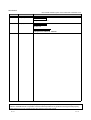
REVISIONS
* The manual number is given on the bottom left of the back cover.
Print Date
Apr., 2003
Jan., 2004
* Manual Number
SH (NA)-080398E-A First printing
SH (NA)-080398E-B Partial corrections
Revision
Chapter 4, Section 5.4
Jul., 2004
SH (NA)-080398E-C Partial corrections
Section 5.5
MODEL CODE change
Changed from 1D0J00 to 1DM208.
Japanese Manual Version SH-080352-C
This manual confers no industrial property rights or any rights of any other kind, nor does it confer any patent
licenses. Mitsubishi Electric Corporation cannot be held responsible for any problems involving industrial property
rights which may occur as a result of using the contents noted in this manual.
2003 MITSUBISHI ELECTRIC CORPORATION
A-2
A-2
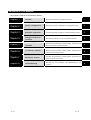
Structure of This Manual
This manual is made up of the following chapters.
Chapter 1
Overview
Describes the features of the gateway functions.
1
Chapter 2
System Configuration
Describes the system configuration of the gateway functions.
2
Chapter 3
Operation Sequence
Provides the general procedure for using the gateway functions.
3
Chapter 4
Settings Common to
Functions
Describes the settings common to the gateway functions.
4
Chapter 5
Server and Client
Functions
Describes the specifications, setting methods, precautions and
Chapter 6
FTP Server Function
Describes the specifications, setting methods, precautions and
Chapter 7
Mail Send Function
Describes the specifications, setting methods, precautions and
Chapter 8
Troubleshooting
Describes the error messages and troubleshooting for the
A-3
others of the server and client functions.
others of the FTP server function.
others of the mail send function.
functions.
A-3
5
6
7
8
INTRODUCTION
Thank you for choosing the Mitsubishi Graphic Operation Terminal.
Before using the equipment, please read this manual carefully to use the equipment to its optimum.
CONTENTS
SAFETY PRECAUTIONS
A- 1
REVISIONS
A- 2
Structure of This Manual
A- 3
INTRODUCTION
A- 4
About Manuals
A- 7
About the Generic Terms and Abbreviations
A- 8
About the Symbols
1. OVERVIEW
A- 11
1- 1 to 1- 3
1.1 Features of Server and Client Functions
1- 1
1.2 Features of FTP Server Function
1- 3
1.3 Featuers of Mail Send Function
1- 3
2. SYSTEM CONFIGURATION
2- 1 to 2- 4
2.1 System Configuration of Gateway Functions
2- 1
2.2 Connection Form
2- 1
2.3 Required Devices
2- 2
2.4 Precautions for Mounting the Communication Board
2- 2
2.5 About the System Programs
2- 4
2.6 Precautions for System Configuration
2- 4
3. OPERATION SEQUENCE
3- 1 to 3- 2
4. FUNCTION SETTING
4- 1 to 4- 4
4.1 GOT Setting
4- 3
4.2 GT Designer2 Setting
4- 4
A-4
A-4
5. SERVER AND CLIENT FUNCTIONS
5.1 Gateway Devices
5- 1 to 5-22
5- 1
5.1.1 What are the gateway devices?.................................................................................... 5- 1
5.1.2 Usable gateway devices ............................................................................................... 5- 2
5.1.3 How to monitor the gateway devices............................................................................ 5- 3
5.1.4 PLC devices that can be assigned ............................................................................... 5- 6
5.2 Specifications
5- 8
5.2.1 Specifications................................................................................................................. 5- 8
5.2.2 Access range that can be monitored ............................................................................ 5- 9
5.3 Setting Method
5-10
5.4 Examples of Use
5-13
5.5 Precautions
5-18
5.6 For Efficient Use
5-20
6. FTP SERVER FUNCTION
6.1 Specifications
6- 1 to 6-13
6- 1
6.1.1 Specifications................................................................................................................. 6- 1
6.1.2 File accessible range..................................................................................................... 6- 2
6.2 Setting Method
6- 3
6.3 Operation on the FTP Client Side
6- 4
6.3.1 Input command at FTP client ........................................................................................ 6- 4
6.3.2 File specifying method................................................................................................... 6- 5
6.3.3 Checking the line connection condition ........................................................................ 6- 6
6.3.4 Line cutoff ...................................................................................................................... 6- 7
6.4 Example of Use
6- 8
6.5 Precautions
6-12
7. MAIL SEND FUNCTION
7.1 Specifications
7- 1 to 7- 8
7- 1
7.1.1 Specifications................................................................................................................. 7- 1
7.1.2 Mail send enabled range.............................................................................................. 7- 2
7.2 Setting Method
7- 3
7.3 Send Examples
7- 4
7.4 Examples of Use
7- 6
7.5 Precautions
7- 8
A-5
A-5
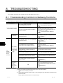
8. TROUBLESHOOTING
8- 1 to 8-9
8.1 Troubleshooting Common to Gateway Functions
8- 1
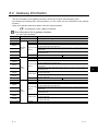
8.2 Gateway Information
8- 2
8.3 Server and Client Functions
8- 4
8.3.1 Error codes and error messages .................................................................................. 8- 4
8.3.2 Troubleshooting............................................................................................................. 8- 6
8.4 FTP Server Function
8- 7
8.4.1 Error codes and error messages .................................................................................. 8- 7
8.4.2 Troubleshooting............................................................................................................. 8- 8
8.5 Mail Send Function
8- 9
8.5.1 Error codes and error messages .................................................................................. 8- 9
8.5.2 Troubleshooting............................................................................................................. 8- 9
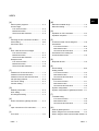
INDEX
A-6
Index- 1 to Index - 2
A-6
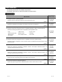
About Manuals
The following manuals are also related to this product.
In necessary, order them by quoting the details in the tables below.
Related Manuals
Manual Number
Manual Name
(Model Code)
GT Designer2 Version1 Operating Manual
SH-080278E
Describes methods of operating GT Designer2 and transmitting data to GOT
(Option)
GT Designer2 Version1 Reference Manual
(1DM205)
SH-080251
Describes the specifications and settings of each object function used in GT Designer2
(Option)
(1DM204)
GOT-A900 Series Operating Manual
(GT Works2 Version1/GT Designer2 Version1 compatible Extended • Option Functions Manual)
Describes the following extended functions and optional functions applicable to GOT
• Utility
• Special module monitor
• Module monitor
• Font change
• Ladder monitor
• Network monitor
• Servo amplifier monitor
SH-080253
• System monitor
• List editing
• CNC monitor
(1DM206)
(Option)
GOT-A900 Series User’s Manual
(GT Works2 Version1/GT Designer2 Version1 compatible Connection System Manual)
SH-080255
Describes the system configuration of which connection method is compatible with GOT-A900 series as well as
processing cables.
(1DM207)
(Option)
A985GOT/A975GOT/A970GOT/A960GOT User's Manual
Explains the performance specifications, installation methods, communication board/communication unit
mounting methods and others of the GOTs.
SH-4005
(1DM099)
(Option)
A950GOT/A951GOT/A953GOT/A956GOT User's Manual
Explains the performance specifications, installation methods, communication board/communication unit
mounting methods and others of the GOTs.
SH-080018
(1DM103)
(Option)
MX Component Version3 Operating Manual
SH-080271
Explains the setting and operating methods of the utilities on MX Component.
(Option)
MX Component Version3 Programming Manual
SH-080272
Explains the programming procedures, detailed descriptions and error codes of the ACT controls.
(Option)
A-7
(13JU32)
(13JF66)
A-7
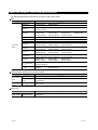
About the Generic Terms and Abbreviations
The following abbreviations and generic terms are used in this manual.
GOT
Generic Term/Abbreviation
A985GOT-V
GOT-A900
Series
Description
A985GOT-TBA-V,
A985GOT-TBD-V
A985GOT
A985GOT-TBA,
A985GOT-TBD,
A985GOT-TBA-EU
A975GOT
A975GOT-TBA-B,
A975GOT-TBA-EU
A975GOT-TBD-B,
A975GOT-TBA,
A975GOT-TBD,
A970GOT
A970GOT-TBA-B,
A970GOT-SBA,
A970GOT-TBA-EU,
A970GOT-TBD-B,
A970GOT-SBD,
A970GOT-SBA-EU,
A970GOT-TBA,
A970GOT-LBA,
A970GOT-LBA-EU
A970GOT-TBD,
A970GOT-LBD,
A97 GOT
A975GOT,
A970GOT
A960GOT
A960GOT-EBA,
A960GOT-EBD,
A960GOT-EBA-EU
A956WGOT
A956WGOT-TBD
A956GOT
A956GOT-TBD,
A956GOT-TBD-M3,
A956GOT-SBD,
A956GOT-SBD-M3,
A956GOT-LBD,
A956GOT-LBD-M3
A953GOT
A953GOT-TBD,
A953GOT-TBD-M3,
A953GOT-SBD,
A953GOT-SBD-M3,
A953GOT-LBD,
A953GOT-LBD-M3
A951GOT
A951GOT-TBD,
A951GOT-TBD-M3,
A951GOT-SBD,
A951GOT-SBD-M3,
A951GOT-LBD,
A951GOT-LBD-M3
A951GOT-Q
A951GOT-QTBD,
A951GOT-QTBD-M3,
A951GOT-QSBD,
A951GOT-QLBD,
A951GOT-QSBD-M3, A951GOT-QLBD-M3
A950GOT
A950GOT-TBD,
A950GOT-TBD-M3,
A950GOT-SBD,
A950GOT-SBD-M3,
A95
A950GOT-SBD-M3-H, A950GOT-LBD-M3-H, A953GOT-SBD-M3-H,
A953GOT-LBD-M3-H
handy GOT
A95 GOT
A956GOT,
A950GOT,
A953GOT,
A950 handy GOT
A950GOT-LBD,
A950GOT-LBD-M3
A951GOT,
A951GOT-Q,
Communication board/Communication module
Generic Term/Abbreviation
Communication
board
Communication
module
Description
Bus connection board A9GT-QBUSS,
A9GT-QBUS2S,
A9GT-BUSS,
A9GT-BUS2S,
Serial communication A9GT-RS4,
board
A9GT-50WRS4
A9GT-RS2,
A9GT-RS2T,
A9GT-50WRS2,
Ethernet
A9GT-J71E71-T
communication module
Option unit
Generic Term/Abbreviation
Option module
A-8
Memory card
interface module
Description
A1SD59J-MIF
A-8
Option
Generic Term/Abbreviation
Option
Description
Memory board
A9GT-FNB,
A9GT-FNB8M,
PC card
(memory card)
Flash PC card/Commercially available flash PC card/SRAM type PC card
Flash PC card
Compact
card
flash
A9GT-FNB1M,
A9GT-QFNB,
A9GTMEM-10MF,
PC
A9GT-FNB2M,
A9GT-QFNB4M,
A9GTMEM-20MF,
A9GT-FNB4M,
A9GT-QFNB8M
A9GTMEM-40MF
Commercially available flash PC card
Software
Generic Term/Abbreviation
Description
GT Works2 Version1 SW1D5C-GTWK2-E
GT Designer2
Version1
Software
SW1D5C-GTD2-E
GT Designer2
GT Designer2 screen creation software for GOT900
GT Simulator2
GT Simulator2 screen simulator for GOT900
GT SoftGOT2
GT SoftGOT2 monitoring software
MX Component
MX Component ActiveX communication support tool
CPU
Generic Term/Abbreviation
QCPU (Q Mode)
QCPU
QnACPU
QCPU (A Mode)
Remote I/O
station
QnACPU type
QnASCPU type
AnUCPU
AnACPU
AnNCPU
AnCPU type
AnUS(H)CPU
ACPU
AnS(H)CPU
A1SJ(H)CPU
AnSCPU type
A1FXCPU
FXCPU
Motion controller
CPU (Q series)
Motion
controller
CPU
Motion controller
CPU (A series)
FA controller
MELDAS C6/C64
A-9
Description
Q00JCPU,
Q00CPU,
Q01CPU,
Q02HCPU,
Q06HCPU,
Q12HCPU,
Q12PHCPU,
Q25PHCPU,
Q12PRHCPU,
Q02CPU-A,
Q02HCPU-A,
Q06HCPU-A
Network module for MELSECNET/H network system remote I/O station
(QJ71LP25-25, QJ72LP25, QJ72BR15)
Q2ACPU,
Q2ACPU-S1,
Q2AHCPU,
Q3ACPU,
Q4ACPU,
Q4ARCPU
Q2ASCPU,
Q2ASCPU-S1,
Q2ASHCPU,
A2UCPU,
A2UCPU-S1,
A3UCPU,
A2ACPU,
A2ACPU-S1,
A3ACPU
A1NCPU,
A2NCPU,
A2NCPU-S1,
AnUCPU,
AnACPU,
AnNCPU
A2USCPU,
A2USCPU-S1,
A2USHCPU-S1
A1SCPU,
A1SCPUC24-R2,
A2SCPU,
A1SHCPU,
A2SHCPU,
A2SHCPU-S1
A1SJCPU,
A1SJCPU-S3,
A1SJHCPU
AnUS(H)CPU,
AnS(H)CPU,
A1SJ(H)CPU
A1FXCPU
A0J2HCPU,
A2CCPU,
A2CCPUC24,
FX0 series,
FX0N series,
FX0S series,
FX1N series,
FX1NC series,
FX1S series,
FX2C series,
FX2N series,
FX2NC series,
FX(2N)-10GM/20GM series,
FX3UC series
Q172CPU,
Q173CPU
A273UCPU,
A373CPU,
A171SCPU,
A171SHCPU,
A172SHCPUN,
LM610,
FCA C6,
A273UHCPU,
A373UCPU,
A171SCPU-S3,
A171SHCPUN,
A173UHCPU,
LM7600,
FCA C64
Q02CPU,
Q25HCPU,
Q25PRHCPU
Q2AHCPU-S1,
Q2ASHCPU-S1
A4UCPU
A3NCPU
A2SCPU-S1,
A2CJCPU
FX1 series,
FX2 series,
A273UHCPU-S3,
A373UCPU-S3,
A171SCPU-S3N,
A172SHCPU,
A173UHCPU-S1
LM8000
A-9
Other PLC
Generic Term/Abbreviation
C200H,
C200H
C200HE),
CV500,
CVM1-CPU11,
CJ1M,
CPM2C,
CQM1,
CV1000,
CVM1-CPU21,
CPM1,
CPM1H
C1000H,
CV2000,
CS1,
CPM1A,
C2000H,
CVM1-CPU01,
CS1D,
CPM2A,
GL60S,
GL130,
MP-930,
GL60H,
CP-9200SH,
MP-940,
GL70H,
CP-9300MS,
MP-9200(H),
GL120,
MP-920,
PROGIC-8
SLC500 series
SLC500-20,
SLC5/02,
SLC500-30,
SLC5/03,
SLC500-40,
SLC5/04,
SLC5/01,
SLC5/05
MicroLogix1000
series
1761-L10BWA,
1761-L16BWB,
1761-L32BWB,
1761-L20BWA-5A,
1761-L10BWB,
1761-L16BBB,
1761-L32BBB,
1761-L20BWB-5A
1761-L16AWA,
1761-L32AWA,
1761-L32AAA,
1761-L16BWA,
1761-L32BWA,
1761-L20AWA-5A,
MicroLogix1500
series
1764-LSP
JW-21CU,
JW-33CUH,
JM-100CU,
JW-22CU,
JW-50CUH,
Z-512J
JW-31CUH,
JW-70CUH,
JW-32CUH,
JW-100CUH,
PROSEC T
series
T3,
T3H,
T2E,
T2N
PROSEC V
series
Model3000,
S2T
Omron PLC
Yaskawa PLC
AllenBradley
PLC
Sharp PLC
Toshiba
PLC
(C200HX,
C200HG,
SIMATIC S7-300series,
Large-sized H
series
H-302(CPU2-03H),
H-4010(CPU3-40H),
H-1002(CPU2-10H),
H-700(CPU-07Ha),
H-200 to 252
series
H-200(CPU-02H,CPE-02H),
H-252(CPU22-02H),
H-252C(CPU22-02HC, CPE22-02HC)
H-250(CPU21-02H),
H-252B(CPU22-02HB),
H series board
type
H-20DR,
H-20DT,
HL-40DR,
H-28DR,
H-28DT,
HL-64DR
H-40DR,
H-40DT,
H-64DR,
H-64DT,
EH-150 series
EH-CPU104,
EH-CPU208,
EH-CPU308,
EH-CPU316
FP0-C16CT,
FP2,
FP5,
FP-M(C32TC)
FP0-C32CT,
FP2SH,
FP10(S),
FP1-C24C,
FP2-CCU,
FP10SH,
FP1-C40C,
FP3,
FP-M(C20TC),
Matsushita Electric Works PLC
A - 10
series
SIMATIC S7-200 series,
SIMATIC S7-400 series
SIEMENS PLC
HITACHI
PLC
(HIDEC H
series)
Description
C200HS,
H-702(CPU2-07H),
H-300(CPU-03Ha),
H-2002(CPU2-20H),
H-2000(CPU-20Ha)
A - 10
About the Symbols
In this manual, the following symbols are used to represent menus and buttons.
Symbols
Description
Represents the menu item to be selected from the menu bar.
[
]
Represents the item in the setting dialog box or the utility menu item of the GOT.
Represents the operation sequence,
to
to
.
Represents the item that provides detailed explanation (manual or the chapter, section or item of that
manual).
Point
Represents the information that you should know.
Represents the information that will be useful.
Remark
A - 11
Represents the supplementary explanation that will be helpful.
A - 11
1. OVERVIEW
1
This manual explains the gateway functions that can be performed on the GOT-A900 series.
There are the following gateway functions to support remote watching and remote maintenance of
production sites from an office.
• Server function
• Client function
• FTP server function
• Mail send function
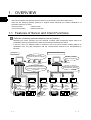
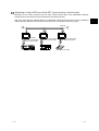
1.1 Features of Server and Client Functions
Collection of data by personal computer (server function)
Monitoring the GOTs (servers) from the personal computer (MX Component) allows data to be
read/written indirectly from/to the PLC CPU devices being monitored by the GOTs.
If the PLC CPU of a different maker is monitored, use of the server function enables data to be
read/written with only MX Component and the communication method to be standardized by
Ethernet.
Previously ...
When server function is used ...
Install peripheral software
programs of various companies.
Necessary software
is MX Component only.
Mitsubishi Company Micro computer
board
A
Communications are
made with personal computer in
respective communication methods
of companies.
MX Component
Communication method
is standardized by Ethernet.
Ethernet
Server
Bus communication
RS-232C
communication
RS-422
communication
Mitsubishi PLC
1-1
RS-232C
communication
RS-422
communication
Company A PLC
RS-232C
communication
RS-422
communication
Micro computer
board
Server
Bus communication
RS-232C
communication
RS-422
communication
Mitsubishi PLC
RS-232C
communication
RS-422
communication
Server
RS-232C
communication
RS-422
communication
Company A PLC Micro computer
board
1-1
Monitoring of other GOTs from client GOT (server function, client function)
Monitoring of the GOTs (servers) from the GOT (client) allows data to be read/written indirectly
from/to the PLC CPU devices being monitored by the GOTs (servers).
Use of the client function enables data to be read/written indirectly from/to the PLC CPUs of different
makers that are different from the maker of the PLC CPU connected to the GOT (client).
Ethernet
Client
Bus communication
RS-232C communication
RS-422 communication
Mitsubishi PLC
1-2
Server
Server
RS-232C communication
RS-422 communication
Company A PLC
RS-232C communication
RS-422 communication
Micro computer board
1-2
1
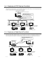
1.2 Features of FTP Server Function
Using the FTP server function, you can read/write data (recipe, alarm history, screen image data) saved
in the PC cards of the GOTs from the personal computer.
General-purpose FTP client tool
R
Windows MS-DOS prompt or command prompt
Recipe data (CSV file),
alarm history data (CSV file)
or screen image data (BMP/JPG file)
are read to personal computer.
Recipe data (CSV file) are written
to PC cards.
Ethernet
PC card
FTP server
function
PC card
FTP server
function
Bus communication
RS-232C communication
RS-422 communication
Mitsubishi PLC
PC card
FTP server
function
RS-232C communication
RS-422 communication
RS-232C communication
RS-422 communication
Micro computer board
Company A PLC
1.3 Features of Mail Send Function
Using the alarm history display function, you can send the occurrence or restoration information of an
error to the personal computer or cellular phone by mail at occurrence of or restoration from the error.
Alarm history display function
Sends alarm occurrence or restoration
information
Intranet mail server
Internet
Personal
computer
Cellular
phone
Ethernet
Mail send
function
Bus communication
RS-232C communication
RS-422 communication
Mitsubishi PLC
1-3
Mail send
function
RS-232C communication
RS-422 communication
Company A PLC
Mail send
function
RS-232C communication
RS-422 communication
Micro computer board
1-3
2. SYSTEM CONFIGURATION
This chapter describes the system configuration of the gateway functions.
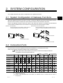
2.1 System Configuration of Gateway Functions
2
When the gateway functions are used, one GOT connects to Ethernet and PLCs and therefore both the
Ethernet communication module and communication board must be mounted to the GOT.
Hence, the gateway functions cannot be used for the GOT that cannot be mounted with the Ethernet
communication module and for the connection form that uses the communication module.
(Example 1) For A951GOT
(Example 2) For CC-Link connection
Since the Ethernet communication module cannot be
Since two different communication modules cannot be
mounted, the gateway functions cannot be used.
mounted to one GOT, the gateway functions cannot be
used.
CC-Link
communication module
Ethernet
communication module
A951GOT
GOT
Ethernet
communication module
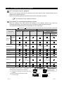
2.2 Connection Form
The GOTs that can use the gateway functions are indicated on a connection form basis.
Refer to the following manual for details of the connection forms.
GOT-A900 Series User's Manual (GT Works2 Version1/GT Designer2 Version1
compatible Connection System Manual)
: Usable
Connection Form
A985
GOT(-V)
A97
GOT
A960GOT
A956W
GOT
: Unusable
A956GOT
A951GOT
A953GOT
A950GOT
*1*2
-M3
(-Q)
: Not connectable
A95
GT
handy
SoftGOT
GOT
Bus connection
CPU direct
connection
Computer link
connection
MELSECNET
connection
CC-Link connection
Ethernet
connection
Third party PLC
connection
Microcomputer
connection
1 When using the A956GOT, use the memory extension type (A956GOT-TBD-M3, A956GOT-SBD-M3,
A956GOT-LBD-M3) GOT.
2 Unable to make RS-232C/RS-422 communication, the A956GOT cannot be connected with the FXCPU or
third-party PLC.
2-1
2-1
2.3 Required Devices
The following devices of the GOTs are required to use the gateway functions.
Application
2
Required Device
Connects GOT to
Ethernet communication module
Ethernet system.
A985GOT
(-V)
A97 GOT
A960GOT
A9GT-J71E71-T (Hardware version E (June, 2002) or later)
Bus connection
A9GT-QBUSS or A9GT-QBUS2S
(QCPU (Q mode))
Bus connection
Connects GOT to Communication (QnA/ACPU)
PLC.
board
RS-232C
communication
RS-422
communication
Executes
gateway
functions with
GOT.
Required to use
FTP server
function.
A956WGOT
A9GT-BUSS or A9GT-BUS2S
2,
2,
A956GOT
-M3
1
3
3
A9GT-RS2 or A9GT-RS2T
A9GT-50WRS2
A9GT-RS4
A9GT-50WRS4
Memory board
A9GT-QFNB (4/8M) or A9GT-FNB (1/2/4/8M)
PC card
JEIDA Ver. 4.2 compliant (PCMCIA 2.1 compliant) PC card
Flash PC card
A9GTMEM-10MF, A9GTMEM-20MF,
A9GTMEM-40MF
Compact flash PC card
Compact FlashTM compliant compact flash PC card
Cannot be
connected.
Not required
4
Cannot be used.
5
Cannot be
used.
1 The gateway functions cannot be used with the hardware version D or earlier.
2 The bus connection module (A9GT-BUSSU, A9GT-BUS2SU, A9GT-QBUS2SU) cannot be used for
the gateway functions.
Use the above bus connection board when making bus connection.
3 The bus connection board (A9GT-50WQBUSS, A9GT-50WBUSS) dedicated to the A956WGOT
cannot be used for the gateway functions.
Use the above bus connection board when making bus connection with the A956WGOT.
4 The memory card interface module is required to use the PC card with the A956WGOT or
A956GOT.
5 The A985GOT cannot use the compact flash PC card. (It can be used with the A985GOT-V only.)
2.4 Precautions for Mounting the Communication
Board
How to mount the communication board to the GOT changes depending on the communication board
used. The precautions for mounting the communication board are described below.
Point
About the mounting of the communication board
Do not mount both the bus connection board and serial communication board to
the GOT.
When using the serial communication board
When mounting the serial communication board, mount it to the GOT as previously.
Refer to the following manual for the way to mount the communication board.
• A985GOT/A975GOT/A970GOT/A960GOT User's Manual
• A950GOT/A951GOT/A953GOT/A956GOT User's Manual
2-2
2-2
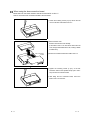
When using the bus connection board
Mount the bus connection board to the back of the A9GT-J71E71-T.
How to mount the bus connection board is shown below.
1) Loosen the mounting screws (2 pcs.) that fix the slot
cover on the back of the A9GT-J71E71-T.
2) Remove the slot cover.
Slot cover
Save the removed slot cover carefully.
(If the A9GT-J71E71-T is used alone without the slot
cover, foreign matter will enter the unit, causing a failure
or malfunction.)
Bus connection
board
3) Fit the bus connection board to the A9GT-J71E71-T.
4) Tighten the mounting screws (2 pcs.) of the bus
connection board to the specified torque (36 to 48N •
cm) to fix the bus connection board.
5) After fitting the bus connection board, mount the
A9GT-J71E71-T to the GOT.
2-3
2-3
2.5 About the System Programs
The system programs compatible with the GOT must have been installed to use the gateway functions.
Refer to the following manual for the system programs necessary for the gateway functions, their
installation methods and precautions.
GT Designer2 Version1 Operating Manual
2.6 Precautions for System Configuration
Connection to the intranet must be fully safeguarded.
Consult the network access provider or network manager (person who does network planning, IP
address management, etc.).
We have no liability for any system problems that occur at the time of connection to the intranet.
If a delay occurs due to network congestion, take preventive measures, e.g. install a bridge.
2-4
2-4
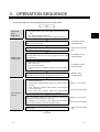
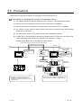
3. OPERATION SEQUENCE
A general procedure for using the gateway functions is given below.
Start
Examine the
system
configuration.
Install the OSs
into the GOTs.
Connect the GOTs
to Ethernet.
Examine the configuration of the whole system.
• Connection structure of the whole system such as the PLCs and
GOTs
• PLC setting (device assignment, etc.)
• GOT setting (IP address, network number, station number, etc.)
3
Connect the GOTs and the personal computer, where GT Designer2 has
started, by the RS-232C cable.
.....GT Designer2 Version1
Operating Manual
Fit the memory boards to the GOTs.
(Not required when the A956GOT is used)
.....User's manual of the used
GOT
Check the ROM_BIOS versions of the GOTs.
If the ROM_BIOS version does not support the gateway functions, install
ROM_BIOS again.
.....GT Designer2 Version1
Operating Manual
Install the system programs into the GOTs.
• Basic function OS
• PLC communication driver
• Extended function OS ("gateway functions" and other necessary
OS)
.....GT Designer2 Version1
Operating Manual
When the GOT is restarted, the utility menu appears. Select "Memory
information" to check whether the installed OSs are correct or not.
.....Extended • Option
Functions Manual
Set the following items in the utility setup of the GOT.
• IP address of the GOT
• Set the NET No. (network number) and PLC No. (station number) of
the GOT.
• When making bus connection with the QCPU, set the extension
number and I/O slots.
• When making other connection, make communication settings,
such as the transmission speed to the PLC, as required.
Fit the communication board to the GOT or Ethernet communication
module and connect it with the PLC by the cable.
(For QnA/ACPU bus connection, make setting with the extension
number and I/O slot switches on the communication board.)
Fit the Ethernet communication module to the GOT and connect the
Ethernet cable.
Section 4.1 in this manual
Connection System Manual
Section 2.4 in this manual
Connection System Manual
.....User's manual of the used
GOT
To next page
3-1
3-1
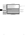
From previous page
Create monitor
screen data.
3
Download the
monitor screen
data.
Debug.
Set the gateway functions to be used.
• When using the server and client functions
Make server and client settings on GT Designer2.
• When using the FTP server function
Make FTP server setting on GT Designer2.
• When using the mail send function
Set the mail of each object on GT Designer2 .
Set the send destination and SMTP server in the mail send setting.
.....Sections 5.3, 6.2, 7.2 in this
manual
Create monitor screen data.
.....GT Designer2 Version1
Reference Manual
Transfer the monitor screen data to the GOTs.
(Transfer by RS-232C communication or transfer using the PC cards)
.....GT Designer2 Version1
Operating Manual
Check the operations of the GOTs.
End
3-2
3-2
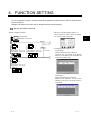
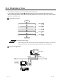
4. FUNCTION SETTING
To use the gateway functions, settings related to the gateway functions must be made on both the GOT
and GT Designer2.
Settings to be made on the GOT and GT Designer2 will be described below.
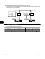
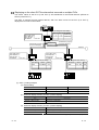
Server and client functions
<System configuration example>
• Utility menu of the GOT (Refer to Section 4.1.)
Set the network No., station number, IP address,
etc. of the GOT itself on each GOT.
MX Component
4
IP address: 10.97.14.20
Ethernet
IP:
10.97.14.254
GOT NW No
:1
GOT PC No
:1
GOT IP address: 10.97.14.10
Router address : 10.97.14.254
Router
GOT NW No
:1
IP:
GOT PC No
:2
GOT IP address: 10.97.14.11
10.97.15.254
Router address : 10.97.14.254
• GT Designer2 (Refer to Section 5.3.)
<Server setting>
Setting of the server function to the GOT.
Assign the PLC CPU devices to the gateway
devices to be accessed by MX Component and
the GOT of the client function.
GOT NW No
:2
GOT PC No
:1
GOT IP address : 10.97.15.10
Router address : 10.97.15.254
<Client setting>
Setting of the client function to the GOT.
Register its the network No., PLC No. and IP
addresses of the GOTs of the server function to
be accessed.
4-1
4-1
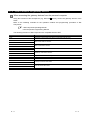
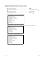
FTP server function
• Utility menu of the GOT (Refer to Section 4.1.)
Set the IP address of the GOT itself on each GOT.
<System configuration example>
General-purpose FTP client tool
R
Windows MS-DOS prompt or command prompt
IP address: 10.97.14.20
Ethernet
GOT IP address: 10.97.14.10
Router address : 10.97.14.254
GOT IP address: 10.97.14.11
Router address : 10.97.14.254
IP:10.97.14.254
Router
IP:10.97.15.254
• GT Designer2 (Refer to Section 6.2.)
<FTP server setting>
Set the login name and password used for connection
of the line of the personal computer and GOT.
4
GOT IP address: 10.97.15.10
Router address : 10.97.15.254
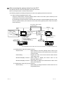
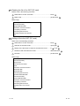
Mail send function
<System configuration example>
• Utility menu of the GOT (Refer to Section 4.1.)
Set the IP address and mail sending of the GOT itself
on each GOT.
Intranet mail server
Internet
IP address: 10.97.14.20
Personal
computer
Cellular
phone
Ethernet
• GT Designer2 (Refer to Section 7.2.)
GOT IP address: 10.97.14.10
Router address : 10.97.14.254
GOT IP address: 10.97.14.11
Router address : 10.97.14.254
IP:
10.97.14.254
Router
<Mail send setting>
Specify the mail server and set the mail address and
others of the send destination.
IP:
10.97.15.254
GOT IP address: 10.97.15.10
Router address : 10.97.15.254
4-2
4-2
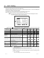
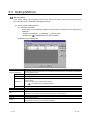
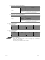
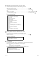
4.1 GOT Setting
Perform the GOT setting in the setup of the utility menu.
Installing the gateway option driver into the GOT or fitting the A9GT-J71E71-T to the GOT displays the
following menu. Make the necessary settings.
The settings to be made change depending on the gateway functions used.
Refer to the following manual for the way to operate the utility menu.
GOT-A900 Series Operating Manual (GT Works2 Version1/GT Designer2 Version1
compatible Extended • Option Functions Manual)
: Setting required
Setting Item
: Setting required depending on condition
Description
: Setting not required (no problem will arise if setting is made)
Factory Setting
GOT NET NO.
Set the network No. of the GOT.
1
GOT PC NO.
Set the station number of the GOT.
1
GOT IP ADDRESS
1
Set the IP address of the GOT.
Set the port No. of the GOT.
ROUTER
ADDRESS
When the system is connected to the other
network by a router, set the router address of 000.000.000.000
the network where the GOT is connected.
SUBNET MASK
2
Client
Function
FTP
Server
Function
Mail Send
Function
000.000.000.000
GOT PORT NO.
2
Server
Function
5001
When the GOT is connected to the Ethernet
network under control of the subnet, set the
255.255.255.000
subnet mask set commonly to the networks.
When the subnet is not used, the default value
is used for operation.
SEND MESSAGE
WAIT
Set the send message wait to reduce the loads
of the network and target PLC.
0
3
SEND MESSAGE
TIME
Set the message time.
3
4
START UP TIME
Set when to start communication (in seconds)
after power-on of the GOT.
3
1 Set the IP address after consulting the network manager (person who does network planning, IP
address management, etc.).
2 Before setting the values, have them checked by the network manager.
3 When sending multiple mails, set the time interval from when one mail is sent until the next mail is
sent.
4 The send message time for connection with the SMTP server at the start of mail sending has been
set to 1 minute (fixed).
Set the send message time after connection of the SMTP server.
4-3
4-3
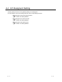
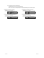
4.2 GT Designer2 Setting
Set the gateway functions in the gateway setting of GT Designer2.
For the settings, refer to the setting methods of the corresponding functions.
• When using the server and client functions
Section 5.3 Setting Method
• When using the FTP server function
Section 6.2 Setting Method
• When using the mail send function
Section 7.2 Setting Method
4-4
4-4
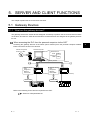
5. SERVER AND CLIENT FUNCTIONS
This chapter explains the server and client functions.
5.1 Gateway Devices
5.1.1 What are the gateway devices?
The gateway devices are virtual devices designed exclusively to perform the server and client functions
on the GOT, and the PLC CPU devices and GOT's internal devices are assigned to the gateway devices
for use.
When accessing the PLC from the personal computer via the GOT
Accessing the gateway devices of the GOTs (server function) from the personal computer enables
indirect access to the PLC CPU devices.
Use MX Component
Version 3 or later.
Personal computer
Mitsubishi PLC
250
D100
Omron PLC
330
TIM50
Access to gateway devices
Ethernet
Gateway device
EG0
Assignment
definition
EG0=TIM50
Gateway device
EG0
Assignment
definition
EG0=D100
GOT (server function)
D100 : 250
GOT (server function)
TIM50 : 330
Mitsubishi PLC
Omron PLC
Refer to the following for the devices required for the GOT.
Section 2.3 Required Devices
5-1
5-1
5
When monitoring the PLC of different maker from one GOT
Accessing the gateway device of the GOT (server function) from the GOT (client function) enables
indirect access to the PLC CPU device.
Access to gateway device
Gateway device
EG0
Assignment
definition
EG0=TIM50
Mitsubishi PLC
D100
250
Omron PLC
TIM50
330
GOT (client function)
GOT (server function)
Access to PLC
D100 : 250
5
TIM50 : 330
Mitsubishi PLC
Omron PLC
5.1.2 Usable gateway devices
The usable gateway devices are indicated below.
Device Name
Device Range
Device Number
Representation
Word device
EG
EG0 to EG32767
Decimal
Bit device
EG
Specified bits of above word devices
Decimal
5-2
Max. Number of Points
32k points
5-2
5.1.3 How to monitor the gateway devices
When accessing the gateway devices from the personal computer
Using the functions of MX Component (e.g. Microsoft Excel), access the gateway devices of the
GOTs.
Refer to the following manuals for the operation method and programming procedure of MX
Component.
R
• MX Component Operating Manual
• MX Component Programming Manual
The following functions of MX Component are compatible with the GOT.
Item
Description
Open
Opens the communication line (starts communication with the GOT).
Close
Closes the communication line (ends communication with the GOT).
ReadDeviceBlock
ReadDeviceBlock2
WriteDeviceBlock
WriteDeviceBlock2
ReadDeviceRandom
ReadDeviceRandom2
WriteDeviceRandom
WriteDeviceRandom2
Batch-reads data from devices.
Batch-writes data to devices.
Randomly reads data from devices.
Randomly writes data to devices.
EntryDeviceStatus
Registers device status watching.
FreeDeviceStatus
Cancels registering device status watching.
OnDeviceStatus
Announces event.
SetDevice
SetDevice2
GetDevice
GetDevice2
GetCpuType
5-3
Changes the device data values.
Gets the device data values.
Gets the GOT model.
5-3
When accessing the gateway device from the GOT
The gateway devices cannot be assigned to the object functions.
Hence, the script function is used to monitor them.
The following explains the setting example for access to the gateway device from the GOT.
(1) When reading the gateway device value
Using the script function, read the gateway device value of the GOT (server function) to the
internal device of the GOT (client function).
By monitoring the value read to the internal device using the numerical display function or like,
the GOT (client function) can monitor the same value as the gateway device value of the GOT
(server function).
EG0 value is read to GD100
by script function.
Ethernet
Mitsubishi PLC
D100
250
Omron PLC
TIM50
330
D100 : 250
GOT internal device
GD100 : 330
GOT (client function)
Script function
Client setting
Numerical display 1 (for Mitsubishi)
Numerical display 2
(for GOT internal device)
Mitsubishi PLC
Gateway device
EG0
Assignment
definition
EG0=TIM50
GOT (server function)
Server setting
TIM50 : 330
Omron PLC
*The read destination of the script function can be set to the device of the Mitsubishi Electric PLC.
(a) Setting items of the GOT (client function)
• Script function ..........................Make setting to read the gateway device value of the
GOT (server function) to the internal device of the GOT
(client function).
• Client setting ............................Register the GOT of the server function whose device
value will be read.
• Numerical display 1 function ....Make setting to display the device value of the
Mitsubishi Electric PLC.
• Numerical display 2 function ....Make setting to display the internal device value of the
GOT (client function).
(b) Setting item of the GOT (server function)
• Server setting ...........................Make setting to assign the device of the Omron PLC to
the gateway device.
5-4
5-4
(2) When writing a value to the gateway device
Using the numerical input function or like, write a value to the gateway device of the GOT
(client function).
Using the script function, write the internal device value of the GOT (client function) the
gateway device of the GOT (server function).
GD100 value is written to EG0
by script function.
Ethernet
Mitsubishi PLC
D100
250
Omron PLC
TIM50 520
GOT internal device
GD100 : 520
D100 : 250
GOT (client function)
Script function
Client setting
Numerical display 1 (for Mitsubishi)
Numerical display 2
(for GOT internal device)
Gateway device
EG0
Assignment
definition
EG0=TIM50
GOT (server function)
Server setting
TIM50 : 520
Mitsubishi PLC
Omron PLC
*The write destination of the script function can be set to the GOT internal device of the sever function.
(a) Setting items of the GOT (client function)
• Script function ..........................Make setting to write the internal device value of the
GOT (client function) to the gateway device of the GOT
(server function).
• Client setting ............................Register the GOT of the server function where the
value will be written.
• Numerical input 1 function .......Make setting to input a value to the device of the
Mitsubishi Electric PLC.
• Numerical input 2 function .......Make setting to input a value to the internal device of
the GOT (client function).
(b) Setting item of the GOT (server function)
• Server setting ...........................Make setting to assign the device of the Omron PLC to
the gateway device.
Point
About details of the script function
Refer to the following manual for details of the script function.
GT Designer2 Version1 Reference Manual
For the examples using the script function, refer to Section 5.4 of this manual.
5-5
5-5
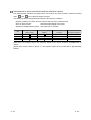
5.1.4 PLC devices that can be assigned
PLC devices that can be assigned
The PLC PCU devices that can be monitored by the GOT and the GOT internal devices can be
assigned to the gateway devices.
Refer to the following manual for the devices that can be monitored by the GOT.
GT Designer2 Version1 Reference Manual
Precautions for monitoring the gateway devices
When the following PLC CPU devices are assigned to the gateway devices, they cannot be
monitored depending on the used script function commands or MX Component functions.
The restricted commands/functions are indicated on a PLC CPU basis.
: No restrictions
: Some devices cannot be used (unusable device names are indicated in parentheses)
Restricted Script Function Commands
Maker Name
bmov, fmov
Word device-
Bit device-
ReadDevice
instruction
specified
specified
Block
(TT, TC, CT, CC)
(Z, BM)
Q/QnA/A/FX
CPU, motion
controller A
Mitsubishi
series
Electric
Motion
controller Q
series
Allen-Bradley PLC
Restricted MX Component Functions
(TT, TN, CU, CD,
(TT, TN, CU, CD,
CN, TP, TA, CP,
CN)
CA)
ReadDeviceRandom
WriteDeviceRandom
Word devicespecified
Bit devicespecified
(TT, TC, CT, CC)
(Z, BM)
(TT, TN, CU, CD,
(TT, TN, CU, CD,
CN, TP, TA, CP,
CN)
CA)
Omron PLC
Sharp PLC
(T, C)
(T, C)
(T, C)
(T, C)
Yaskawa PLC
Toshiba PLC
Hitachi PLC
Matsushita Electric
Works PLC
(Z, T, C)
(Z, T, C)
(TD, SS, WDT,
MS, TMR, CU,
RCU, CT, R, DIF,
DFN)
(TD, SS, WDT,
MS, TMR, CU,
RCU, CT, R, DIF,
DFN)
(T, C)
(T, C)
SIEMENS PLC
(Example) When the bmov instruction is used with the script function
The gateway device to which TT (Allen-Bradley PLC
device) has been assigned cannot be monitored.
1 The devices not indicated in the above table can be
monitored.
2 Can be monitored if the bit device-specified
command is used.
Script function
bmov instruction
GOT
(client function)
Mitsubishi Electric PLC
5-6
Device TT is assigned
to gateway device.
EG0=T4:0/14(TT)
GOT
(server function)
Allen-Bradley PLC
5-6
Remark
Restricted script function commands
There are restrictions on the following script function commands.
Refer to the following manual for details of the commands.
GT Designer2 Version1 Reference Manual
• Word device-specified command names
Item
Description
Applied
arithmetic
operation
Function
sin, cos, tan, asin, acos, atan, abs, log, log10, exp,
ldexp, sqrt
• Bit device-specified command names
Item
Operator
Description
Bit device
&, |, ~, ^, <<, >>
Substitution
=
Device operation set, rst, alt
5-7
5-7
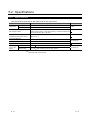
5.2 Specifications
5.2.1 Specifications
The specifications of the server and client functions are given below.
Item
Port number
Specifications
Server function
5011
Client function
5012, 5013
Setting Method
Fixed
Max. number of nodes
Recommended: Max. 64 units
(GOT (server function) + GOT (client function) + personal computer that
communicates with GOTs = 64 units)
Number of clients (GOT, personal
computer) that can access servers
(GOTs) simultaneously
Max. 5 units
Other node designation
IP address designation, max. 128 units
Gateway device
32k points of word devices: EG0 to 32767
Compatible MX Component
MX Component Version 3 (SW3D5C-ACT(-A)) or later
Memory space
used by GOT
(bytes)
Server function
20 + 20
number of assigned gateway device points
Client function
16 + 20
preset number of GOTs of server function
1
GT Designer2
GT Designer2
1 If six or more clients (GOT, personal computer) make simultaneous access to the servers (GOTs),
the scripts of the clients may stop.
5-8
5-8
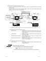
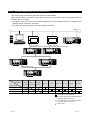
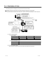
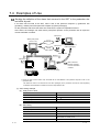
5.2.2 Access range that can be monitored
The access range of the server and client functions is shown below.
When the PLC CPU is monitored via the GOT, only the PLC CPU device set to the gateway device of
the GOT can be accessed.
• The device of the PLC CPU as the network destination can be monitored when it is assigned to the
gateway device of the GOT connected.
• The GOT cannot monitor the PLC CPU of Ethernet connection.
Ethernet
Personal computer
(MX Component)
GOT 1)
Bus connection
RS-232C/RS-422 communication
PLC 2)
PLC 3)
GOT 2)
PLC 1)
Bus connection
RS-232C/RS-422 communication
PLC 6)
MELSECNET or like
PLC 5)
PLC 4)
Monitor
Destination
Personal
computer
GOT 1)
(Server)
GOT 2)
(Server)
PLC 1)
PLC 2)
PLC 3)
PLC 4)
PLC 5)
PLC 6)
1)
1)
1)
1)
2)
1)
1)
1)
1)
Monitor Source
Personal computer
2)
GOT 1) (client)
GOT 2) (client)
: Can monitor the gateway device
: Can monitor the PLC CPU device.
1) : Can monitor the PLC CPU device assigned to
the gateway device of the GOT 1).
2) : Can monitor the PLC CPU device assigned to
the gateway device of the GOT 2).
: Cannot monitor.
5-9
5-9
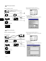
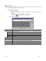
5.3 Setting Method
Server setting
In the server setting, set the gateway device to be used by the GOT of the server function and the
PLC CPU device to be assigned to that gateway device.
(1) Server function setting method
(a) Operation procedure
When either of the following operations is performed, the Gateway server dialog box is
displayed.
• Choose the [Common]
[Gateway]
[Server] menu.
• Double-click
(Gateway Server) in the workspace.
(b) Gateway server dialog box
Item
Assignment setting list
Description
Set the gateway devices used for the GOT of the server function and the PLC CPU devices to be assigned
to those gateway devices.
EG Device
Set the gateway device to which the PLC CPU device will be assigned.
Type
Select the type of the device to be assigned.
PLC Device
Set the N/W number, PLC station number, CPU number and device of the PLC CPU to be assigned to the
gateway device.
Refer to the following for the device setting method.
GT Designer2 Version1 Reference Manual
Points
OK
Register the consecutive device points in "Points" for the device type already set.
Used to confirm the settings and close the dialog box.
Cancel
Used to cancel the settings and close the dialog box.
Add
Used to add new assignment settings.
Click this switch to display the EG Device setting dialog box, and make settings.
Delete
After selecting the setting, click this switch to delete the setting.
Delete All
Used to delete all settings.
Check
Used to check whether the settings are correct or not.
If any setting is incorrect, the error message is displayed.
5 - 10
5 - 10
(2) Precautions for device assignment
A gateway device is set on a two point basis.
Hence, the number of assigned points changes depending on the set device type.
(a) Assignment of bit device (1-bit device)
It is assigned on a 32 point basis.
(Example) When M0 is assigned to EG0
EG0
M15 to M0
EG0
D0
EG1
M32 to M16
EG1
D1
(c) Assignment of word device (32-bit device)
It is assigned on a 1 point basis.
(Example) When CN200 (32 bits) is assigned to EG0
5 - 11
(b) Assignment of word device (16-bit device)
It is assigned on a 2 point basis.
(Example) When D0 (16 bits) is assigned to EG0
(d) Assignment of 8-bit device
It is assigned on a 4 point basis.
(Example) When E0000 is assigned to EG0
EG0
CN200 (lower bits)
EG0
E0001
E0000
EG1
CN200 (upper bits)
EG1
E0003
E0002
5 - 11
Client setting
In the client setting, register the N/W No., PLC No. and IP address of the GOT of the server function
to be monitored by the GOT of the client function.
(1) Client function setting method
(a) Operation procedure
When either of the following operations is performed, the Gateway client dialog box is
displayed.
• Choose the [Common]
[Gateway]
[Client] menu.
• Double-click
(Gateway Client) in the workspace.
(b) Gateway client dialog box
Item
Server function GOT list
Description
Set the N/W numbers, PLC numbers, types, etc. of the GOTs of the server function to be monitored by the
GOT of the client function.
N/W No.
Register the network No. of the corresponding GOT.
PLC No.
Register the PLC No. (station number) of the corresponding GOT.
Type
Fixed to GOT.
IP address
Register the IP address of the corresponding GOT.
Port No.
Fixed to 5011.
Communication
Fixed to UDP.
OK
Used to confirm the settings and close the dialog box.
Cancel
Used to cancel the settings and close the dialog box.
Add
Used to add a new GOT of the server function.
Click this switch to add the GOT of the server function, and make settings.
Delete
After selecting the settings, click this switch to delete the settings.
Delete All
Used to delete all settings.
Copy
After selecting the settings, click this switch to copy the settings.
5 - 12
5 - 12
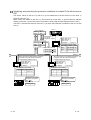
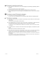
5.4 Examples of Use
The following gives the examples of using the sever and client functions.
Making access to the PLC from the personal computer via the GOT
The device values of EG0 to EG5 of the GOT 1) (server function) are displayed on MX Component.
MX Component
EG devices (EG0 to EG5)
of GOT 1) are monitored.
EG0:150 EG1:480
EG2:230 EG3:370
EG4: 80 EG5: 25
Device batch-read function is issued to GOT
to monitor EG0 to EG5 devices of GOT.
Ethernet
GOT utility menu
:1
GOT NET No.
:2
GOT PC No.
GOT IP address : 10.97.14.2
GOT 1)
PLC devices (D10 to D15)
are monitored.
D10:150 D11:480
D12:230 D13:370
D14: 80 D15: 25
GT Designer2 Gateway server setting
EG device
Points
Device
EG0
6
0-FF D10
Bus connection
RS-422 communication
RS-232C communication
PLC device values
D10:150 D11:480
D12:230 D13:370
D14: 80 D15: 25
PLC
(1) GOT 1) setting example
(a) Server setting
EG Device
EG
Device
0-FF D10
Type
Word
Points
6
(b) Numerical display function
Item
Description
Device
D10 to D15
Network
Host
(2) Personal computer setting
Set the personal computer in the environment where Ethernet can be used.
5 - 13
5 - 13
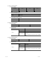
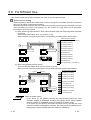
Displaying on the client GOT the alarms that occurred on multiple PLCs
The device values of the PLC 2) and PLC 3) are transferred to the internal devices (GD100 to
GD147) of the GOT 1)
The GOT 1) monitors its own internal devices, and if an alarm occurs on the PLC 2) or PLC 3),
displays the occurrence information.
PLC 1)
GOT utility menu
GOT NET No. :1
GOT PC No. :1
: 10.97.14.1
IP address
GOT 1)
GT Designer2 client setting
NET No. PLC No. IP Address
10.97.14.2
1
2
10.97.14.3
1
3
GOT internal devices
Transferred by script 1)
(5 second sampling)
GD100 to 131
GD132 to 147
Transferred by script 2)
(5 second sampling)
Ethernet
GOT utility menu
GOT NET No. : 1
GOT PC No. : 2
: 10.97.14.2
IP address
GOT 2)
GOT utility menu
GOT NET No. : 1
GOT PC No. : 3
: 10.97.14.3
IP address
GT Designer2 server setting
EG device
Device
Points
EG0
0-FF IB200 512
GOT 3)
GT Designer2 server setting
EG device
Device
Points
EG0
0-FF ..300
256
PLC 2)
PLC 3)
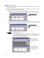
(1) GOT 1) setting example
(a) Client setting
NET No
PLC No
IP Address
1
2
10.97.14.2
1
3
10.97.14.3
(b) Alarm list display function (for GOT 2) alarm display)
Item
Description
Number of device points
512 points (consecutive)
Device
GD100.b0
(c) Alarm list display function (for GOT 3) alarm display)
Item
Description
Number of device points
256 points (consecutive)
Device
GD132.b0
Preset the comments that will be displayed by the alarm list display functions.
5 - 14
5 - 14
(d) Script function (for GOT 2) alarm display)
Item
Script 1)
Description
Type
Screen script
Trigger type
Sampling, 5 sec
Data format
Unsigned BIN 16-bit
Script description
bmov([1-2:w:EG0],[w:GD100],32);
//Transfers the data of 32 points, starting from EG0,
of GOT 2) to GD100 and later of GOT 1).
(e) Script function (for GOT 3) alarm display)
Item
Script 2)
Description
Type
Screen script
Trigger type
Sampling, 5 sec
Data format
Unsigned BIN 16-bit
Script description
bmov([1-3:w:EG0],[w:GD132],16);
//Transfers the data of 16 points, starting from EG0,
of GOT 3) to GD132 and later of GOT 1).
(2) GOT 2) setting example
(a) Server setting
EG Device
EG0
Device
0-FF
IB200
Type
Bit
Points
512
(3) GOT 3) setting example
(a) Server setting
EG Device
EG0
Point
Device
0-FF
..300
Type
Bit
Points
256
About the trigger type
When using the script function, do not set the trigger type as [Ordinary] or
[Sampling, within 2 seconds].
Doing so may affect the other monitor operations.
5 - 15
5 - 15
Monitoring and controlling the production conditions of multiple PLCs with the server
GOT
The device values of the PLC 2) and PLC 3) are transferred to the EG devices of the GOT 1)
(devices of the PLC 1)).
When values are written to the PLC 1), the EG devices of the GOT 1) (internal devices (GB100,
GB101) of the GOT 1)) turn ON. (Check completion of write using the lamp display function or like.)
The GOT 1) monitors the devices of the PLC 1) to check the production conditions of the PLC 2) and
PLC 3).
PLC 1)
PLC 1) devices
D100
D101
233
523
EG0.b0/EG1.b1
turn ON at
completion of write.
EG0.b0
EG0.b1
EG2
EG3
OFF
OFF
233
523
ON
ON
GOT 1)
GOT internal devices
GB128 OFF ON
GB129 OFF ON
GOT utility menu
GOT NET No. : 1
GOT PC No. : 1
IP address
: 10.97.14.1
GT Designer2 server setting
EG device Device
Points
EG0
0-FF GB128 32
EG2
0-FF D100
2
Ethernet
When the bit device that indicates production
completion turns ON, HR200 value (233)
is transferred to EG2 by script 1).
GOT 2)
GOT utility menu
GOT NET No. : 1
GOT PC No. : 2
: 10.97.14.2
IP address
GT Designer2 client setting
N/W No. PLC No. IP Address
1
1
10.97.14.1
When the bit device that indicates production
completion turns ON, W200 value (523) is
transferred to EG3 by script 2).
GOT 3)
GT Designer2 client setting
N/W No. PLC No. IP Address
1
1
10.97.14.1
Bit device that indicates
Production completion:
OFF ON
Bit device that indicates
Production completion:
OFF ON
PLC 3) device
PLC 2) device
HR200 233
PLC 2)
5 - 16
GOT utility menu
GOT NET No. : 1
GOT PC No. : 3
: 10.97.14.3
IP address
W200
523
PLC 3)
5 - 16
(1) GOT 1) setting example
(a) Server setting
EG Device
Device
Type
Points
EG0
0-FF
GB128
Bit
32
EG2
0-FF
D100
Word
2
(b) Numerical display function
Item
Description
Device
D100 to D101
Network
Host
(c) Lamp display function (set two)
Item
Description
Device
GB100 to GB101
Network
Host
(2) GOT 2) setting example
(a) Client setting
NET No
PLC No
1
IP Address
1
10.97.14.1
(b) Script function
Item
Description
Type
Screen script
Trigger type
While ON, bit device that indicates production completion
Data format
Unsigned BIN 16-bit
Script description
[1-1:w:EG2]=[w:HR200]; //Writes the production count to
the PLC 1).
set ([1-1:b:EG0.00]); //Turns ON the write completion
signal.
Script 1)
(3) GOT 3) setting example
(a) Client setting
NET No
PLC No
1
IP Address
1
10.97.14.1
(b) Script function
Item
Description
Type
Screen script
Trigger type
While ON, bit device that indicates production completion
Data format
Unsigned BIN 16-bit
Script description
[1-1:w:EG3]=[w:W200]; //Writes the production count to the
PLC 1.
set ([1-1:b:EG0.01]); //Turns ON the write completion
signal.
Script 2)
5 - 17
5 - 17
5.5 Precautions
This section provides the precautions for using the server and client functions.
Precautions for assigning the devices in the gateway setting
(1) The gateway devices are set as at least two points, and set on a two point basis thereafter.
(2) When a bit device is assigned, 32 points are set, starting from the set device.
(3) When a device was not assigned, the unassigned area (empty area) is on a word basis.
(4) The network number and PLC station number must be set to assign the MELSEC-A/QnA/Q
series PLC CPU devices.
(5) The CPU number must be set to assign the CPU of the multiple PLC system.
(6) If station No. is changed while monitoring the gateway device to which PLC CPU device has
been assigned,the monitored device is irrelevant to the station No. change.
Example) When station No. is changed on the GOT (server)
Use the script function to read EGO to the GOT internal device.
Ethernet
GOT internal devices
GD100:250
GD100(D100)
250
Station No. is changed
Station number
switching device
Gateway device
EG0
Assignment
definition
EG0=D100
D50 00FF
D100
200
Monitoring D100 in the
numeric display
GOT(Server function)
GOT(Client function)
D100:250
Station No.0
Monitoring
(00FF)
Station No.1
D100:200
D100:100
Station
No.3
D100:150
If station No. is changed on the GOT (server),
the station No. change is irrelevant to the
GOT (client) that monitors D100 assigned to the
gateway device.
5 - 18
0101
Station No.1
(0101)
Station
No.2
As D100 has not been assigned to the gateway device
on the GOT (server), station No. change is executed.
5 - 18
Precautions for setting the script function
(1) When setting the script function, do not set the trigger type to [Ordinary] or [Sampling, within 2
seconds].
Doing so may affect the other monitor operations.
(2) The script function cannot be used to monitor the gateway devices of the GOT itself.
When monitoring the PLC devices assigned to the gateway devices, monitor the PLC devices
directly.
Precautions for using GT Simulator for debugging
(1) GT Simulator cannot debug the gateway functions.
An error will occur if the gateway device is monitored or data is written to the gateway device.
Precautions for monitoring
(1) If the GOT monitors devices by transient communication via the network, the monitor speed
will decrease.
To increase the monitor speed, use link devices.
(2) If the gateway device of the GOT of the server function is monitored in a status where the
server and client functions cannot be used , an error occurs and the script stops.
While power is off, when the ROM_BIOS version of the GOT is incompatible, or when the memory board is not fitted,
for example.
(3) The gateway device, to which the PLC device has not been assigned, is monitored as 0 (OFF
for bit).
When write is executed, the written value is invalid.
(4) If the screen save of the GOT is canceled (by a screen touch or the human sensor) during
execution of the script that uses the gateway devices, it may take some time to cancel.
When the execution of automatic screen save has been specified, it may take more time than
the specified.
(For example, when the script processing time is 2 seconds, the screen save is canceled in a
maximum of 2 seconds after the screen is touched.)
5 - 19
5 - 19
5.6 For Efficient Use
This section explains the points for efficient use of the server and client functions.
Script function setting
When the gateway devices are used directly to execute a program, the number of times to access the
other GOT increases, slowing the processing.
By performing batch read from the GOT internal devices and performing batch write after execution
of the processing as shown in the following (1), the number of access times can be decreased,
improving the processing speed.
(1) When performing batch read from GOT internal devices (GD) and performing batch write after
processing
Access to the other station GOT occurs twice (1), 3)).
When one time of access requires 50ms, the necessary processing time is about 100ms.
Script description example
1)
1)
bmov([1-2:w:EG0], [w:GD100],10);
[w:D200]=[w:GD100];
[w:D201]=[w:GD101];
3)
[w:D202]=[w:GD102];
EG0 to EG9
[w:D203]=[w:GD103];
GD100 to GD109
Server
Client
2) Processing
2)
[w:D204]=[w:GD104];
[w:GD105]=128;
[w:GD106]=[w:D106];
[w:D205]=[w:GD107];
[w:D206]=[w:GD108];
[w:GD109]=5433;
3)
bmov([w:GD100], [1-2:w:EG0],10);
(2) When using gateway devices directly
Access to the other station GOT occurs 10 times (1) to 10)).
When one time of access requires 50ms, the necessary processing time is about 500ms.
Script description example
1),2),3)
8),9),10)
1)
[w:D200]=[1-2:w:EG0];
2)
[w:D201]=[1-2:w:EG1];
3)
[w:D202]=[1-2:w:EG2];
4)
[w:D203]=[1-2:w:EG3];
5)
[w:D204]=[1-2:w:EG4];
6)
[1-2:w:EG5]=128;
7)
[1-2:w:EG6]=[w:D106];
8)
[w:D205]=[1-2:w:EG7];
9)
[w:D206]=[1-2:w:EG8];
10)
[1-2:w:EG9]=5433;
EG0 to EG9
Server
Client
D106
D200 to D206
Point
About the written values
In the above (1), the gateway devices are batch-accessed when the script
execution condition is established. Therefore, the gateway device values available
when the condition is established can be processed as the written values.
In the above (2), the gateway devices are accessed one by one after the script
execution condition is established. Therefore, the written values may differ from the
gateway device values available when the condition is established.
5 - 20
5 - 20
Gateway device setting
When assigning the PLC devices to the gateway devices, set the same type of devices of the same
PLC together where possible.
By setting the same devices of the same PLC together as in the following (1), the number of access
times can be reduced, improving the processing speed.
(1) Devices of host, other station and other PLC are set together
When the GOT of the client function accesses the host devices of the GOT of the server
function, access can be made with the program that reads 50 points starting from EG0 (1)).
Script description example
1)
bmov([W:GD100], [1-2:w:EG0],50);
(2) Devices of host, other station and other PLC are set not together
When the GOT of the client function accesses the host devices of the GOT of the server
function, access requires the program that reads 40 points starting from EG0 (1)) and the
program that reads 10 points starting from EG130 (2)).
Script description example
1)
bmov([W:GD100], [1-2:w:EG0], 40);
2)
bmov([w:GD140], [1-2:w:EG130], 10);
To further increase efficiency
By reserving together in advance the PLC devices to be used for the server and
client functions in the system design stage as shown in the following (a), the
number of times for the GOT of the server function to access the PLC can be
decreased, improving the processing speed.
(a) When PLC devices are assigned together
When 100 points of
devices are accessed,
access to the PLC occurs
only once.
(b) When PLC devices are not assigned together
When 100 points of
devices are accessed,
access to the PLC must
be made five times.
5 - 21
5 - 21
Performance of server and client functions (reference values)
The following table indicates the performance of the server and client functions (reference values)
when
and
on the previous pages are used.
The reference values of the performance assume the following conditions.
• System consists of one GOT of server function and one GOT of client function
• GOT of server function
: Numerical input setting of 64 points
• GOT of client function
: Numerical input setting of 64 points
• Number of assigned device points : Word devices of 10 points
Item
bmov is used
(Batch access)
Device are assigned
together
Response speed for bus
connection
Response speed for
CPU direct connection
1
Approx. 140ms
Approx. 260ms
2
Approx. 700ms
Approx. 1300ms
3
Approx. 700ms
Approx. 1300ms
4
Approx. 700ms
Approx. 1300ms
When there are multiple clients, the response speed is the "above response speed number of
clients".
(When there are five clients in above "1", the response speed for bus connection is approximately
700ms.)
5 - 22
5 - 22
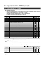
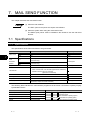
6. FTP SERVER FUNCTION
This chapter descries the FTP server function.
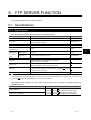
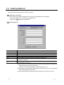
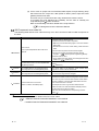
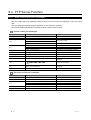
6.1 Specifications
6.1.1 Specifications
The specifications of the FTP server function are indicated below.
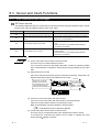
Item
Specifications
Setting Method
FTP server function setting
Whether the function will be used or not can be set (default: Not used)
GT Designer2
User name
1 to 12 alphanumeric characters (case sensitivity, anonymous must not
be used) (default: GOT900)
GT Designer2
Password
1 to 8 alphanumeric characters (case sensitivity) (default: GOT900)
GT Designer2
Port number
20, 21
Fixed
Number of clients that can connect
simultaneously
1 unit
Fixed
1 minute
Fixed
1 to 60 minutes (default: 15 minutes)
GT Designer2
Time set to
watching timer
of command
input
1
Before login
After login
2
File size that can be read
Unlimited (max. read size depends on PC card capacity.)
File name
Within 8 characters of only alphanumeric characters
(longer file name not acceptable)
Access mode
Normal: Reference mode (write to PC card disabled)
Write is enabled after issue of dedicated command
FTP client
• General-purpose FTP client tool can be used. 3
• Access can be made by FTP command from Windows
prompt or command prompt.
Memory space used by GOT (bytes)
12 + 2
R
6
MS-DOS
total number of login name and password characters
GT Designer2
1 The line is cut off if a correct password and login name are not entered within 1 minute after line connection with the GOT.
2 The GOT cuts off the line if a command is not input from the FTP client within the time set to the watching timer of command input.
R
3 Microsoft Internet Explorer and Netscape Communicator are unusable.
The following table indicates the FTP client tools that have been confirmed to operate properly by
Mitsubishi Electric.
Name
FFFTP (freeware)
NextFTP Ver. 2 (shareware)
6-1
Compatible OS
Microsoft R
Microsoft R
Microsoft R
Microsoft R
Windows R 98 operating system,
Windows R Millennium Edition operating system,
WindowsNT R Workstation4.0 operating system,
Windows R 2000 Professional operating system
6-1
6.1.2 File accessible range
The FTP server function can access on the PC card of the GOT within the network to which the FTP
client is connected. (Multiple clients cannot access the PC card of the GOT simultaneously.)
When using a relay device such as a router, consult the network manager.
Personal computer
(FTP client)
Ethernet
GOT
(FTP server function)
Router
PLC
6
GOT
(FTP server function)
PLC
Simple judgment of whether file access is possible or not
Simple judgment of whether file access is possible or not can be made by issuing
the ping command to the GOT.
Example of issuing the ping command (Windows
IP address of GOT: 10.97.14.10
R
MS-DOS prompt)
• When file can be read
C:\ping 10.97.14.10
pinging 10.97.14.10 with 32 byte of data:
reply from 10.97.14.10: bytes=32 time<10ms ttl=128
reply from 10.97.14.10: bytes=32 time<10ms ttl=128
reply from 10.97.14.10: bytes=32 time<10ms ttl=128
C:\
• When file cannot be read
C:\ping 10.97.14.10
pinging 10.97.14.10 with 32 byte of data:
request timed out.
request timed out.
request timed out.
C:\
6-2
6-2
6.2 Setting Method
Operation procedure
When either of the following operations is performed, the FTP dialog box is displayed.
• Choose the [Common]
[Gateway]
[FTP] menu.
• Double-click
(FTP) in the workspace.
FTP dialog box
Item
Description
Use FTP Server
Check here when using the FTP server function.
Login Name
Set the login name used when the FTP client connects to the GOT.
You can set only one login name up to 12 characters.
Only alphanumeric characters (a to z, A to Z, 0 to 9) can be used.
Password
Set the password used when the FTP client connects to the GOT.
You can set only one password up to 8 characters.
Only alphanumeric characters (a to z, A to Z, 0 to 9) can be used.
Watching timer of
command input
Set when the line with the GOT will be cut off if no command is entered from the FTP client.
You can set this time between 1 and 60 minutes in 1 minute increments.
Normally use it as default (15 minutes).
6-3
6-3
6.3 Operation on the FTP Client Side
6.3.1 Input command at FTP client
General commands
The following table indicates the correspondences between the commands that can be used with a
general FTP client tool and the FTP server function of the GOT.
The usable commands change depending on the FTP client tool used.
For details, refer to the manual of the used FTP client tool.
: Usable
Command
Name
: Unusable
: Setting invalid (command does not result in error)
Reference
Mode
Function
append
Additionally writes a file to the GOT (PC card).
ascii
Changes the file transfer mode to the ascii mode.
binary
Changes the file transfer mode to the binary mode.
bye
Exits the FTP client tool.
cd
Changes the current directory of the GOT (PC card).
close
Cuts off the line with the GOT.
delete
Deletes a file in the GOT (PC card).
dir
Reads the file information in the GOT (PC card).
get
Reads a file from the GOT (PC card).
1
ls
Displays file names in the GOT (PC card).
mdelete
Deletes multiple files specified using a wild card.
mdir
Reads the file information in the GOT (PC card) to the specified file.
mget
Reads multiple files.
mkdir
Creates a directory in the GOT (PC card).
mls
Reads the file names in the GOT (PC card) to the specified file.
mput
Writes the specified multiple files using a wild card to the GOT.
open
Connects the line with the GOT.
put
Write a file to the GOT (PC card).
pwd
Creates the current directory of the GOT.
quit
Cuts off the line with the GOT to exit the FTP client tool.
quote
Used when the GOT-dedicated command is used. (Example: quote gtwr)
user
Enters the user name and password used to log in to the GOT.
Write
Mode
1
1 Since this command is fixed to "No file conversion (binary)" in the FTP server function, it is invalid if set.
2 The rename and rmdir commands are unusable.
GOT-dedicated commands
When the line with the GOT is connected, the FTP client is in the "reference mode" in which only file
read is enabled.
Before executing file write, delete or directory creation, change it to the "write mode".
To select the reference mode or write mode, issue a mode change command.
: Usable
Command
Name
: Setting invalid (command does not result in error)
Function
quote gtwr
Changes the FTP server function mode of the GOT to the write mode.
quote gtrd
Changes the FTP server function mode of the GOT to the reference mode.
quote help
Displays the general-purpose actual commands of the FTP protocol supported by the
FTP server function of the GOT.
6-4
Reference
Mode
Write
Mode
6-4
6.3.2 File specifying method
There are two file specifying methods: one is to specify one file directly and the other is to specify
multiple files that meet the condition.
Specifying the file name to read
Specify the file name, period and extension of the file to be specified.
File name
+ .
+ Extension
Represents the file type.
Separates the file name and extension.
The file name to be read.
The FTP server function mainly uses files having the following extensions.
Extension
csv
Application on GOT
Recipe file (recipe function), alarm history file (alarm history display function)
bmp
Monitor screen image (hardcopy function)
jpg
Specifying the files that meet the condition (wild card)
When specifying multiple files, you can use " " or "?" as a wild card.
(Example)
When specifying only JPEG files....................................................... .jpg
When specifying the CSV files that begin with Main ......................... Main .csv
When specifying the files whose extensions begin with b................. .b??
Point
(1) Precautions for specifying the file name
For the FTP server function, do not put a space into a file name or extension.
The file that has a space cannot be read or written as a correct file name.
(2) About data in PC card
The PC card of the GOT contains the files that can cause the operation fault of
the GOT if they are deleted.
To prevent the operation fault of the GOT, do not access the folders, which
store the above files, from the FTP client.
<Folder structure in the PC card>
For alarm history file storage
For recipe file storage
the FTP server
For report file storage
For screen image file storage
function.
Work file for printer printout
For monitor screen data storage (for screen copy)
Cannot be used
For OS storage (for OS copy)
with the FTP
For OS system screen storage (for OS copy)
server function.
For special function module monitor data storage
(for screen copy)
Do not delete files.
For motion monitor data storage (for screen copy)
For servo amplifier monitor data storage
(for screen copy)
* In addition to the above, do not delete the file whose extension is "ini"
(GOT information file).
Can be used with
6-5
ALARMHST
RECIPE
REPORT
SNAPSHOT
SNAPHDCP.BMP
USERDATA
OS
SYSTEMD
SPCDATA
6-5
6.3.3 Checking the line connection condition
The connection condition of the line between the GOT and FTP client is stored into the GOT special
register GS200.b2 (bit position: 2).
By referring to this bit on the GOT, you can check whether the line is connecting or not.
Device Name
ON
GS200.b2
OFF
Connecting
Cut off
Refer to the following manual for details of the GOT special registers.
GT Designer2 Version1 Reference Manual
Example of using GS200.b2
(1) Using the above device with the lamp display function, you can create a line
condition confirmation lamp.
GS200.b2 : OFF
GS200.b2 : ON
Line Connecting
(2) By setting the above device to the operation condition as a trigger using the
touch key function or numerical input function, you can restrict operation (input)
while the line is connecting.
GS200.b2 : OFF
Manufacturing line
A
B
C
GS200.b2 : ON
Manufacturing line
Operation is
Adisabled while line
Bis connecting.
C
Using the touch key function or numerical
input function, make setting to enable input
only when the device (GS200.b2) is OFF.
6-6
6-6
6.3.4 Line cutoff
There are two line cutoff methods: automatic cutoff and manual cutoff.
Automatic cutoff
The GOT cuts off the line automatically if no command is entered from the FTP client within the time
set to the watching timer of command input in the FTP server setting.
The watching timer of command input is always set.
Refer to the following for the setting of the watching timer of command input.
Section 6.2 Setting Method
Manual cutoff (Forcibly cutting off the line)
Using the GOT special register GS400.b2 (bit position: 2), you can cut off the line forcibly.
When you want to cut off the line, turn "ON" GS400.b2 (bit position: 2).
Refer to the following manual for details of the GOT special registers.
GT Designer2 Version1 Reference Manual
Point
Precautions for use of GS400.b2
After confirming that the line has been cut off, always turn "OFF" GS400.b2.
Remark
About line cutoff
Since the GOT cannot detect the fault status of the FTP client, it does not cut off
the line immediately if the FTP client could not exited properly (e.g. the personal
computer was powered off while the line is connecting).
However, as the watching timer of command input has been set, the line is cut off
automatically in the predetermined period of time.
6-7
6-7
6.4 Example of Use
The example of using the FTP server function is described below.
In this example of use, the Windows MS-DOS prompt is used to access the GOT and FTP client.
When performing operation using the commercially available FTP client tool or like, refer to the manual
of the FTP client tool used.
R
General procedure
Start
Connect the line of the GOT and FTP client.
Refer to
Read the file of the GOT (PC card).
Refer to
Write a file to the GOT (PC card).
Refer to
Operate the directory of the GOT (PC card).
Refer to
Cut off the line of the GOT and FTP client.
Refer to
End
Point
Precautions for file write
When writing a file to the GOT (PC card) or operating the directory, turn ON the
memory card access switch of the GOT to make the PC card write-enabled.
System configuration
FTP client
File read
FTP server
(IP address:
10.97.14.200)
6-8
File write
Directory operation
PC card
6-8
Connecting the line of the GOT and FTP client.
Connect the GOT and FTP client in the following procedure.
Start of the FTP client .............................................................. ftp
Connection with the GOT ........................................................ open IP address of GOT
Input of the login name ............................................................ login name
Input of the password .............................................................. password
Login image (when the line was connected properly)
C:\>ftp
ftp>open 10.97.14.200
connected to 10.97.14.200
220 GOT900 FTP server ready.
user:GOT900
331 Password required.
Password:****
230 User logged in.
ftp>
Login image (when the other personal computer has already connected to the GOT)
C:\>ftp
ftp>open 10.97.14.200
connected to 10.97.14.200
220 GOT900 FTP server ready.
user:GOT900
530 Not logged in.
ftp>
Login image (when the password is incorrect)
C:\>ftp
ftp>open 10.97.14.200
connected to 10.97.14.200
220 GOT900 FTP server ready.
user:GOT900
331 Password required.
Password:****
530 Not logged in.
ftp>
6-9
6-9
Reading the file of the GOT (PC card).
Read the file in the following procedure.
Notification of no file conversion .............................................. binary
Read of file............................................................................... get file name
Read image
ftp>binary
200 Command Okey.
ftp>get SNAP0001.BMP
200 PORT command successful
150 Opening connection.
226 Closing data connection.
250 bytes received in 0.02 seconds
ftp>
Writing a file to the GOT (PC card).
Write a file in the following procedure.
Notification of no file conversion .............................................. binary
Selection of the write mode ..................................................... quote gtwr
Display of the file name to check for the same file name ........ ls
or dir
Deletion made if the same file exists ....................................... delete file name
File write................................................................................... put file name
Write image
ftp>binary
200 Command Okey.
ftp>quote gtwr
200 command successful.
ftp>ls
200 PORT command successful
SNAP0001.BMP
SNAP0002.BMP
226 Closing data connection.
ftp>delete SNAP.0001.BMP
200 Command Okey.
ftp>put SNAP0001.BMP
200 PORT command successful
150 Opening connection.
226 Closing data connection.
250 bytes sent in 0.01 seconds.
ftp>
6 - 10
6 - 10
Operating the directory of the GOT (PC card).
Create and change the directory in the following procedure.
Current directory display .......................................................... pwd
Selection of the write mode ..................................................... quote gtwr
Directory creation..................................................................... mkdir directory name
Current directory change ......................................................... cd directory name
Directory operation image
ftp>pwd
257 “A:\snapshot” is current directory.
ftp> quote gtwr
200 command successful.
ftp>mkdir bmpdata
275 MKD command successful.
ftp>cd bmpdata
250 CWD command successful.
ftp>pwd
257 “A:\snapshot\bmpdata” is current directory
ftp>cd ..
250 CWD command successful.
ftp>pwd
257 “A:\snapshot” is current directory.
ftp>
Cutting off the line of the GOT and FTP client.
Cut off the GOT and FTP client in the following procedure.
Quit command ......................................................................... quit
Logout (line cutoff) image
ftp>quit
221 User logged out. Good-Bye.
C:\>
Error display
An error that occurred in the FTP server function is displayed on the FTP client.
Refer to the following for the displayed error messages.
Section 8.2 Error Messages
If an attempt was made to read an non-existing file snap0010.bmp
ftp>get snap0010.bmp
200 PORT command successful.
550 snap0010.bmp•No such file or directory.
C:\>
6 - 11
6 - 11
6.5 Precautions
The following are the precautions for using the FTP server function.
Precautions for system design using the FTP server function
(1) When writing a recipe file from the FTP client to the GOT, set the format of the recipe file as set
for the recipe function of the GOT.
When writing a recipe file from a remote location, confirm the operation with the field site
personnel before executing write.
(2) Before using the FTP client tool, refer to the manual of the FTP client tool, confirm its functions
and operation methods, and make tests before starting operation.
Depending on the FTP client tool used, the GOT (FTP server) may not support some
operations.
Also, depending on the FTP client tool used, the FTP server function may not be usable since
the GOT cannot support the extended command (quote) and issue the GOT-dedicated
command.
(3) If a number of files are read at once under one command (e.g. get or put is executed by
specifying a wild card), processing may be delayed by network congestion. If processing is
slow, issue commands separately to perform the processing separately.
Precautions for file read
(1) The GOT cuts off the line if no command is input from the FTP client for longer than the time
set to the watching timer of command input.
(2) The line is cut off if any of the GOT IP address, router address and subnet mask is changed
while the line of the GOT and FTP client is connecting.
(3) The line is kept connected if the GOT is put offline (e.g. the monitor screen data is
downloaded) while the line of the GOT and FTP client is connecting.
(4) When you want to change (rewrite) the contents of the recipe file, make the recipe inactive.
If the recipe file in the PC card is deleted during recipe processing, the function will not operate
properly.
If the recipe file is deleted other than during recipe processing, an error (system alarm: recipe
file error) will occur in the next recipe operation.
(
Section 6.3.3 Checking the line connection condition)
(5) Do not delete the printer printout temporary file.
If the printer printout temporary file is deleted, the function will not operate properly.
(6) If the FTP client has become faulty (personal computer), wait until the time set to the watching
timer of command input elapses or turn ON the forced logout signal "GS400.b2" to cut off the
line, and log in again.
The line connecting condition can be checked using GS200.b2 (bit position: 2).
(7) Do not power off the GOT while access is being made from the FTP client to the file in the PC
card of the GOT.
Doing so may damage the data in the PC card.
6 - 12
6 - 12
(8) If you reset the GOT or switch power off while the line of the GOT and FTP client is connecting,
the operation of the FTP client depends on the specifications of the FTP client tool used.
Use the FTP client tool that supports the detection of an FTP server fault or that can be exited
properly.
(9) Access to a file cannot be made if the memory card access switch of the GOT is OFF.
(10)Write processing (put) cannot be performed if the write protect switch of the GOT is ON.
(11) The GOT does not use any file whose file name is 8 or more characters long.
Hence, if the PC card contains a file whose file name is 9 or more characters long, it cannot be
accessed from the FTP client.
Set the file name of a file to be accessed to within 8 characters (except a period and
extension).
(12)Depending on the used FTP client tool, the time stamp may differ from that of the file in the PC
card of the GOT.
If the time stamp differs, check the setting of the FTP client tool.
Precautions for FTP login
(1) If you have forgotten the password for FTP login, connection to the GOT cannot be made. You
can confirm the set password on GT Designer2.
(2) You cannot log in to the GOT from multiple FTP clients simultaneously.
6 - 13
6 - 13
7. MAIL SEND FUNCTION
This chapter describes the mail send function.
Point
(1) About the mail software
The GOT (send source) does not require mail software.
(2) About the system when using the mail send function
The SMTP (mail) server must be installed in the intranet to use the mail send
function.
7.1 Specifications
7.1.1 Specifications
The specifications of the mail send function are given below.
Item
SMTP server
Port
7
Send
destination
address
Specifications
Setting Method
IP address setting (1 server only)
Fixed
25
Fixed
Server certification
Disabled
To
1 to 32 (max. 64 characters for 1 address: Alphanumeric
characters only)
Cc
Bcc
0 to 32 (max. 64 characters for 1 address: Alphanumeric
characters only)
Subject
Max. 128 characters (alphanumeric characters only)
Text data size
Either of the following two different comments can be sent.
Alarm comment: Max. 512 characters (alphanumeric characters)
Detailed comment: Max. 512 characters
(alphanumeric characters)
Attached file
Disabled
Encoding
No
Compression
No
Memory space used by GOT (bytes)
20 + 4 (number of destinations + 2) + 2
destination, subject and sender characters)
GT Designer2
GT Designer2
(total number of
GT Designer2
The following table indicates the mail software programs that have been confirmed to operate properly
by Mitsubishi Electric.
Name
Maker
OutlookExpress5
Microsoft
Netscape Communicator 4.7 or later
Netscape
AL-Mail32 Version1.12 (shareware)
Winbiff
7-1
Orange Software
Compatible OS
Microsoft R
Microsoft R
Microsoft R
Microsoft R
Microsoft R
Windows R 95 operating system,
Windows R 98 operating system,
Windows R Millennium Edition operating system,
WindowsNT R Workstation4.0 operating system,
Windows R 2000 Professional operating system
7-1
7.1.2 Mail send enabled range
Since the IP address is used to specify the SMTP server in the mail send function of the GOT, a dial-up
router cannot be utilized to send mail. (The SMTP server in the Internet service provider cannot be
used.)
Install the SMTP (mail) sever in the intranet.
SMTP (mail) server
Internet
Personal computer
Cellular
phone
Ethernet
Mail is sent
Dial up
router
Internet
GOT
Personal computer
Cellular
phone
PLC
7
7-2
7-2
7.2 Setting Method
Only one mail send setting can be made for one GOT.
Operation procedure
When either of the following operations is performed, the Mail dialog box is displayed.
[Gateway]
[Mail] menu.
• Choose the [Common]
• Double-click
(Mail) in the workspace.
Mail dialog box
Item
Available E-Mail
SMTP Server
FROM
1
SUBJECT
3
TO
Description
Check here when using the mail send function.
Set the IP address of the SMTP server used.
Enter the address of the mail send source. (Alphanumeric characters only)
2
Enter the title of the mail. (Alphanumeric characters only)
Enter the address of the mail send destination. (Alphanumeric characters only)
CC
Enter the address of the mail send destination (copy). (Alphanumeric characters only, mail can be sent if
this address is not entered.)
BCC
Enter the address of the mail send destination (hidden copy). (Alphanumeric characters only, mail can be
sent if this address is not entered.)
1 Since the GOT does not have the mail receive function, set the reply destination in "FROM" when
the mail receiver from the GOT will make a reply.
When there is no specific reply destination, set the address as set in "TO".
2 When mail is to be received from multiple GOTs, the GOTs that have sent mail can be identified if
you enter different subjects into the GOTs.
3 When setting multiple send destination addresses, separate them with a space or comma.
7-3
7-3
7.3 Send Examples
When e-mail is sent from GOT to the target device, the reception header part shown at the destination
displays a message that shows that the e-mail is from GOT.
Example of display in the reception header part at the destination
From:**********************
To:************************
Cc:************************
Subject:GOT 01
:
X-Mailer:GOT
Point
About mail send
(1) The format and contents of the display of e-mail sent vary depending on the
mailer specifications used at the destination.
(2) When e-mail is sent to a mobile phone, the display may vary depending on the
specifications (screen size) of the mobile phone.
(3) GOT can send up to 16 e-mail at one time. If alarms occur 17 times or more,
the 17th e-mail and subsequent are not sent.
When sending e-mail using the alarm history display function
If an alarm occurs in GOT, the time and information of the alarm are sent to the destination by e-mail.
Moreover, if the alarm recovers, the time and information of the alarm recovery are sent to the
destination by e-mail.
Refer to the following manual for the way to set the alarm history display function.
GT Designer2 Version1 Reference Manual
(1) Example of display at the destination (when an alarm occurred)
(a)
(b)
[Alarm history occurred information]
[Occur Time]
2002/11/28 09:48:15
[Occur Information]
Line A supply conveyor stopped.
[detailed Information]
Alarm history: A-line supply converter stopped.
Check the power source.
(a) The comment entered in the alarm history display function is displayed.
(b) The content of detailed display entered in the alarm history display function is displayed.
"Detail Information" is not displayed if the detail display setting of the alarm history
display function has not been made or has been made for the base or window screen.
("Alarm history: detail comment nothing" appears under "Detail Information ".)
To display "Detail Information ", make the detail display setting in the comment window.
7-4
7-4
(2) Example of display at destination (when an alarm recovered)
[Alarm history repaired information]
[repair Time]
2002/11/28 10:38:23
[repair Information]
Alarm "Line A supply conveyor stopped." recovered.
Alarmhistory:detail comment nothing
7-5
7-5
7.4 Examples of Use
Sending the definition of the alarm that occurred in the GOT to the production site
and office by mail
If an alarm has occurred in the GOT, mail is sent to the personal computer 1) (production site
(operator)), cellular phone and personal computer 2) (office (manager)).
On the production site where the alarm was received, the system is repaired/recovered.
At the office, the manager can send mail to prompt the operator on the production site to report the
current restoration condition.
Mail is sent
SMTP (mail) server
(10.97.14.12)
Internet
Personal computer 2)
(Office (manager))
Mail is sent
Internet
Cellular phone
Ethernet
Mail is sent
Mail is sent
Mail is returned*
Operator is asked
to check restoration
condition.
GOT
(10.97.14.1)
Personal computer 1)
(Production site (operator))
PLC
Since the GOT cannot receive mail, set FROM as the mail address of the personal computer or like on the
production site.
This allows the mail to be returned from the office (manager) to the production site and the mail requesting
confirmation of the restoration condition to be sent to the production site.
(1) GOT setting example
(a) Utility menu of GOT
Item
Description
IP address
10.97.14.1
Send message wait
000
Send message time
03 seconds
Startup time
003 seconds
10ms
(b) Mail setting
Item
SMTP (mail) server
7-6
Description
10.97.14.12
FROM
Mail address of personal computer 1)
TO
Mail address of personal computer 1)
CC
Mail address of personal computer 2)
Mail address of Cellular phone
subject
GOT01
7-6
(c) Alarm history display function (alarm history common setting)
Item
Description
Monitor device
Mail send
Send mail
Occurred/restored
Preset the comment to be displayed for the alarm history display function.
7-7
7-7
7.5 Precautions
The precautions for using the mail send function are described below.
(1) The languages that can be sent by mail is only English.
The other languages are sent as "?" by mail.
(2) The GOT refers to the PLC CPU clock every 60 minutes.
Note that if the time is changed on the PLC side, an error of up to 60 minutes will be produced.
(3) The mail send date/time is the time of the SMTP server at the time of send.
7-8
7-8
8. TROUBLESHOOTING
This chapter describes the troubleshooting of the gateway functions.
8.1 Troubleshooting Common to Gateway Functions
The following troubleshooting is common to the gateway functions.
Phenomenon
Definition and Cause
The mounting position of the serial
communication board is incorrect.
The GOT displays the "Check
Communication" message.
The version of the ROM_BIOS. OS installed in
the GOT is incorrect.
The ERR. LED is
lit on the PLC.
1
The used A9GT-J71E71-T is not compatible with
the gateway functions.
The used A9GT-J71E71-T is not compatible with
the gateway functions.
8
The extended function OS of the gateway
functions has not been installed in the GOT.
The
gateway
functions
are not
executed.
When all bits of
GS200 are OFF
and no response
is made to Ping
2, 3
Corrective Action
Mount the serial communication board on the
GOT.
(
User's Manual of used GOT)
Match the versions of the OSs to be installed.
(All versions of the basic function OS, PLC
communication driver and extended function OS
should be Ver. 9.*.* or later.)
(
GT Designer2 Version1 Reference
Manual)
Use the A9GT-J71E71-T (hardware version E
(June, 2002) or later) that is compatible with the
gateway functions.
(
Section 2.3)
Use the A9GT-J71E71-T (hardware version E
(June, 2002) or later) that is compatible with the
gateway functions.
Section 2.3)
(
Install the extended function OS of the gateway
functions into the GOT.
(
GT Designer2 Version1 Reference
Manual)
The memory board has not been mounted.
(When A985GOT, A97 GOT, A960GOT or
A956WGOT is used)
Mount the memory board to the GOT.
The memory extension type (-M3 type) GOT is
not used. (When A956GOT is used)
Use the memory extension type (-M3 type) GOT.
The IP address has not been set to the GOT.
Using the utility function of the GOT, check
whether the IP address has not been set to the
GOT.
The mounting position of the bus connection
board is incorrect.
Mount the bus connection board on the
A9GT-J71E71-T.
Section 2.4)
(
When any of the
GS200 bits is
ON and
response is
made to Ping
2, 3
Refer to the troubleshooting of the function
corresponding to the ON bit and take a corrective
action.
(
Section 8.2)
1 "1401 : SP. UNIT DOWN" is displayed in the PLC diagnostics of GX Developer.
2 Refer to the following for details of the gateway common information (GS200).
Section 8.2 Gateway Information
3 Check whether response is made to Ping or not by issuing the Ping command to the GOT from the
personal computer.
Example: ping "IP address of GOT" in Command Prompt
8-1
8-1
8.2 Gateway Information
The error information of the gateway functions is stored into the GOT special registers (GS).
By monitoring the following GOT special registers, you can confirm the error information of the gateway
functions.
Refer to the following manual for details of the GOT special registers.
GT Designer2 Version1 Reference Manual
Error information list of gateway functions
(1) GOT write information
Device
Function
Description
GS200
GS201
GS202
Gateway common information Refer to (a) on the next page.
Error counter
Stores the number of error occurrences.
Error code
Stores the error code (refer to Section 8.4.1).
Stores the year (upper byte, 2 lower digits of year) and month (lower byte) of the error
GS203
occurrence date and time in BCD code.
Mail send
Occurrence date Stores the day (upper byte) and hour (lower byte) of the error occurrence date and time
function
GS204
and time
in BCD code.
Stores the minute (upper byte) and second (lower byte) of the error occurrence date and
GS205
time in BCD code.
Reserved
GS206 to 209
GS210
Error counter
Stores the number of error occurrences.
GS211
Error code
Stores the error code (refer to Section 8.2.1).
Stores the year (upper byte, 2 lower digits of year) and month (lower byte) of the error
GS212
occurrence date and time in BCD code.
Occurrence date Stores the day (upper byte) and hour (lower byte) of the error occurrence date and time
GS213
and time
in BCD code.
Server
Stores the minute (upper byte) and second (lower byte) of the error occurrence date and
function
GS214
time in BCD code.
Stores the lower part of the IP address of the GOT (client function) where the error
GS215
occurred in BIN code.
Request source
Stores the upper part of the IP address of the GOT (client function) where the error
GS216
occurred in BIN code.
Reserved
GS217 to GS219
GS220
Error counter
Stores the number of error occurrences.
GS221
Error code
Stores the error code (refer to Section 8.2.1).
Stores the year (upper byte, 2 lower digits of year) and month (lower byte) of the error
GS222
occurrence date and time in BCD code.
Occurrence date Stores the day (upper byte) and hour (lower byte) of the error occurrence date and time
GS223
and time
in BCD code.
Client
Stores the minute (upper byte) and second (lower byte) of the error occurrence date and
function
GS224
time in BCD code.
Stores the lower part of the IP address of the GOT (server function) where the error
GS225
occurred in BIN code.
Request source
Stores the upper part of the IP address of the GOT (server function) where the error
GS226
occurred in BIN code.
GS227 to GS229
Reserved
8-2
8-2
8
(2) GOT read information
Device
GS400
Function
Description
Gateway common control
Refer to (b) given below.
(a) Gateway common information (GS200)
b15
b14
b13 to b12
b0
b1
b2
b3
b4
b5 to b10
b11
b12 to b13
b14
b15
b11
b10 to b5
b4
b3
b2
b1
b0
: ON while the mail send function is ready.
: ON while the FTP server function is ready.
: Turns ON when the FTP client logs in.
: ON while the server function is ready.
: ON while the client function is ready.
: Reserved
: Turns ON when an error occurs in the mail send function.
: Reserved
: Turns ON when an error occurs in the server function.
: Turns ON when an error occurs in the client function.
(b) Gateway common control (GS400)
b15
b14
b13 to b12
b11
b10 to b3
b2
b1 to b0
b0 to b1
b2
b3 to b10
b11
: Fixed at OFF.
: Turns ON to cause forced logout in the FTP server function.
: Fixed at OFF.
: Turns ON to clear the error of the mail send function
(GS200.b11, GS201 to GS206).
b12 to b13 : Fixed at OFF.
b14
: Turns ON to clear the error of the server function
(GS200.b14, GS210, GS211).
b15
: Turns ON to clear the error of the client function
(GS200.b15, GS220, GS221).
8-3
8-3
8.3 Server and Client Functions
8.3.1 Error codes and error messages
GOT error code list
The following table lists the error codes that are stored into the GOT special registers GS211 (server
function error code) and GS221 (client function error code).
Error Code
Definition and Cause
Corrective Action
490
An attempt was made to monitor the gateway
device of the GOT itself using the script function.
491
An attempt was made to access a non-existing Check the network number, PLC station number and Ethernet
station.
settings of the monitor destination.
492
A communication time error occurred.
1. Increase the "send time-out" period in the utility menu of the
GOT.
2. Check the network. (Check firewall presence/absence,
execute Ping, for example.)
A communication error occurred.
1.Check for cable disconnection and check the module
mounting status.
2. Check the network. (Check firewall presence/absence,
execute Ping, for example.)
493
1.Set the other GOT as the monitor destination in the script.
2. Do not use the script but directly monitor the PLC devices.
The error that will occur in the GOT of the server function is the error code 493 only.
Point
(1) If error code 493 occurs in GOT of server function
This error may occur when networks coexist.
If no error has occurred on the target client side, it poses no specific problem
since communication is restored to normal by the retry processing on the client
side.
(2) System that uses a router
If the error code 493 occurred in the GOT of the server function, note that the IP
address of the target client is the address of the router.
Ethernet
At 493 error, not the IP
address of the client but
the IP address of the router
(10.97.14.254) is stored
into the GOT internal device.
IP : 10.97.15.254
Router
Server
GOT IP address: 10.97.14.10
IP : 10.97.15.254
Client
GOT IP address: 10.97.15.10
(3) If an error occurs in the GOT with client function.
If an error occurs in the GOT with client function, the script will stop.
Take the corrective action and then re-execute the script.
Refer to the following manual for details of “Script function”.
GT Designer2 Version1 Reference Manual
(4) If error code 492 occurs in GOT of client function
This error may occur when there are many clients that access the server.
To increase the "send time-out period", set the value of "already set send
time-out period number of clients".
8-4
8-4
(5) If error code 15 (script was not terminated after elapse of script watching time)
was stored into the script error data (GS16 to GS47) when script that used
gateway devices was used
This error may occur when there are many clients that access the server.
To increase the script watching time (GS385), set the value of "already set
script watching time number of clients".
Refer to the following manual for details of the script function.
GT Designer2 Version1 Reference Manual
MX Component error code list
The following table lists the error codes that may occur when access is made from MX Component to
the GOT.
Error Code
0 0180840B
Definition and Cause
Time-out error
Time-out period elapsed but data could not be
received.
Corrective Action
1. Corrective action for MX Component
• Reexamine the time-out value in Properties.
• Make the communication setting again in the communication
setting utility.
• Reexamine the PLC CPU, module setting, cable status and
others.
• Exit from MX Component once and execute it again.
• Exit from the program and restart the DOS/V personal
computer. (
MX Component Programming Manual)
2. Corrective action for GOT
• Check whether the server setting of GT Designer2 has been
made or not. (
Section 5.3)
The used A9GT-J71E71-T is not compatible with
the gateway functions.
Use the A9GT-J71E71-T that is compatible with the gateway
functions.
(
Section 2.3)
0 010F4030
An unusable device or non-existing device has
been assigned to the accessed gateway device.
In the server setting of GT Designer2, check whether device
assignment is correct or the set device exists.
0 010F4031
The PLC device outside the monitor range has In the server setting of GT Designer2, check whether the device
been assigned to the accessed gateway device.
within the monitor range has been assigned.
0 010F4B00
1. Check for cable disconnection and check the communication
board/communication module mounting status and PLC status.
2. This error may occur if the PLC load increases at other station
access. At that time, move the other station data to the host
PLC and monitor them on the host.
3. If the sequence scan is long, insert the COM instruction.
4. Check the GOT error codes of the alarm list display function
(system alarm) and system information.
If an error has occurred, take the corresponding corrective
action. 1
Communication time-out occurred.
Module or cable is not loaded properly.
1 About the GOT error codes
Refer to the following manuals for details of the GOT error codes.
• A985GOT/A975GOT/A970GOT/A960GOT User's Manual
• A950GOT/A951GOT/A953GOT/A956GOT User's Manual
8-5
8-5
8.3.2 Troubleshooting
The following table indicates the troubleshooting for use of the server and client functions.
Phenomenon
Gateway device
cannot be
monitored.
8-6
Definition and Cause
Corrective Action
A non-existing device is monitored in the server
setting.
Check the PLC CPU device assigned to the gateway device.
The IP address of the GOT to be monitored is
wrong in the client setting.
Check the IP address of the GOT to be monitored.
An error occurs in the GOT with server function
or client function.
Confirm the GOT special register GS211 and GS221, and then
take the corrective action.
(
Section 8.2.1 Error code/Error message)
The script function error occurs.
Confirm the script function error and then take the corrective
action. (
GT Designer2 Version1 Reference Manual)
8-6
8.4 FTP Server Function
8.4.1 Error codes and error messages
The error codes and error messages related to the FTP server function are displayed on the FTP client
side.
The error displaying method changes depending on the used FTP client tool.
The following tables indicate the errors that the GOT sends to the FTP client.
Normal codes and messages
code
message
Description
125
Data Connection already open; transfer starting
Transfer is started.
150
Opening connection
Connection for transfer is established.
Command okay.
200
Command is normal.
Command successful.
214
PORT command successful.
PORT command succeeded.
The following commands are recognized.
Supported command list
Help end.
HELP display ends.
Syntax: <command name>
HELP display of corresponding command
220
GOT900 FTP server ready.
Connection is established.
221
User logged out. Good-Bye.
Connection ends.
226
Closing data connection.
Connection for transfer ends.
230
User logged in.
Login succeeded.
250
CWD command successful.
CWD (current directory change) command
succeeded.
257
"A:\
directory.
275
MKD command successful.
MKD (directory creation) command
succeeded.
331
Password required.
Password is required.
/
/
.
" is current
Current directory display
Abnormal codes and messages
Error code
Error message
Description
426
Connection closed; transfer aborted.
500
Syntax error, command unrecognized.
Syntax error, command cannot be recognized.
Command not supported.
Unsupported command
510
Transfer error
Port open fails.
Port open failed.
File open fails.
File open failed.
530
Not logged in.
Login failed.
550
Requested action not taken.
Command execution failed.
8-7
8-7
8.4.2 Troubleshooting
The following table indicates the troubleshooting for use of the FTP server function.
Phenomenon
Line cannot be connected.
Definition and Cause
Corrective Action
[Use FTP server function] is not checked in the
FTP server setting of GT Designer2.
Check [Use FTP server function].
The other device has logged in to the GOT.
After the other device has logged in, connect
to the line again.
Issue the Ping command to the GOT and
check for a reply.
Ask the manager for confirmation.
Login cannot be made.
File cannot be written.
File cannot be read.
File cannot be deleted.
The login name or password is wrong.
Enter the correct login name or password.
(Case sensitive)
The file name is 9 or more characters long.
Reduce the file name to "8 characters" + "." +
"extension".
The reference mode is selected.
Change to the write mode.
Overwrite disable or similar setting has been
made in the FTP client setting.
Reexamine the FTP client setting.
The file of the same name exists.
Delete the file or change the file name so that
the file of the same name does not exist.
The PC card is write-protected.
Cancel the write protection of the PC card.
The memory card access switch of the GOT is
OFF.
Turn ON the memory card access switch of
the GOT.
An attempt was made to read the file that does
not exist.
Check for the file using the dir or ls command.
The memory card access switch of the GOT is
OFF.
Turn ON the memory card access switch of
the GOT.
The PC card is write-protected.
Cancel the write protection of the PC card.
The memory card access switch of the GOT is
OFF.
Turn ON the memory card access switch of
the GOT.
GOT was powered off during login.
Since the file being transferred may have
been corrupted, do not use but delete it.
(The operation of the FTP client changes
depending on the specifications of the FTP
client.)
FTP client software was forcibly
exited during login.
Log in to the GOT again after the time set to
the watching timer of command input in the
FTP server setting has elapsed.
(The GOT logs out after the time set to the
command has elapsed.)
8-8
8-8
8.5 Mail Send Function
8.5.1 Error codes and error messages
The following table indicates the error codes stored into the GOT special register GS202 (mail send
function error code).
Error Code
Definition and Cause
Corrective Action
2
The FROM address has not been set.
Set FROM.
(Mail send setting on GT Designer2)
3
The SMTP server has not been set.
Set the SMTP server.
(Mail send setting on GT Designer2)
4
The send destination address has not been set.
Set the send destination (TO).
(Mail send setting on GT Designer2)
5
The mail address is incorrect.
Check whether the mail address settings of FROM,
TO, CC and BCC are correct.
(Mail send setting on GT Designer2)
6
The number of alarms that occurred may be greater
than the number of alarms that can be sent by mail.
Check the number of alarms that occurred. (Max.
number of queuing alarms: 16)
10
The SMTP server could not be connected.
1. Check whether the SMTP server is normal or not.
2. Check whether the IP address setting of the
SMTP server is correct or not. (Mail send setting
on GT Designer2)
3. Ask the network manager about the router
address and sub-net mask and set the returned
data in the setup of the GOT.
4. When a firewall has been built on the network,
ask the network manager if it has been set to
pass through the port 25.
11
Time-out occurred at the time of connection with the
SMTP server.
1. Check whether the SMTP server is normal or not.
2. Increase the send message time value.
(Setup screen of GOT)
12
Error notification is given from the SMTP server.
1. Check whether the SMTP server is normal or not.
2. Ask the network manager if mail can be sent
without certification. (e.g. POP3 certification)
8.5.2 Troubleshooting
The following table indicates the troubleshooting for use of the mail send function.
Phenomenon
Definition and Cause
Corrective Action
The SMTP server does not operate properly.
Ask the network manager if the SMTP server is
operating properly.
FROM of the send source is not set correctly.
Check whether FROM of the send source is set
correctly.
An attempt was made to send 17 or more mails at
one time.
Reduce the number of mails to be sent
simultaneously to 16 or less.
Time of sent mail is
incorrect.
The time of the SMTP server is wrong. (The GOT
sends mail at the time of the SMTP server.)
Check whether the time of the SMTP server is
precise or not.
Sentence of mail sent
(received) by cellular
phone is broken midway.
The number of characters that can be sent (received)
by the cellular phone was exceeded.
Reduce the number of characters in the sentence
sent by mail to within the number of characters that
can be sent (received) by the corresponding cellular
phone.
Mail is not sent.
8-9
8-9
INDEX
[A]
About system programs ................................. 2- 4
Access range
FTP server function .................................... 6- 2
Mail send function....................................... 7- 2
Server and client functions......................... 5- 9
Ind
[M]
Mail send enabled range ................................7- 2
Mail send setting .............................................7- 3
[O]
Operation on FTP client side..........................6- 4
Operation sequence .......................................3- 1
[C]
Checking the line connection condition ......... 6- 6
Client setting.................................................. 5-12
Connection form ............................................. 2- 1
[E]
Error codes and error messages
FTP server function .................................... 8- 7
Mail send function....................................... 8- 9
Server and client functions......................... 8- 4
Example of use
FTP server function .................................... 6- 8
Mail send function....................................... 7- 6
Server and client functions........................ 5-13
[F]
Features of FTP server function .................... 1- 3
Features of mail send function....................... 1- 3
Features of server and client functions ......... 1- 1
File specifying method ................................... 6- 5
FTP server setting .......................................... 6- 3
Function setting .............................................. 4- 1
[G]
Gateway information ...................................... 8- 2
GOT setting .................................................... 4- 3
GT Designer2 setting ..................................... 4- 4
[H]
How to monitor the gateway devices............. 5- 3
[P]
PLC devices that can be assigned.................5- 6
Precautions
FTP server function....................................6-12
Mail send function .......................................7- 8
Server and client functions ........................5-18
Precautions for mounting the
Communication board ....................................2- 2
[R]
Required devices ............................................2- 2
[S]
Server setting .................................................5-10
Setting method
FTP server function.....................................6- 3
Mail send function .......................................7- 3
Server and client functions ........................5-10
Specifications
FTP server function.....................................6- 1
Mail send function .......................................7- 1
Server and client functions .........................5- 8
System configuration ......................................2- 1
System configuration of gateway functions ...2- 1
[T]
Troubleshooting
FTP server function.....................................8- 8
Mail send function .......................................8- 9
Server and client functions .........................8- 6
[I]
Input command on FTP client side ................ 6- 4
[L]
Line cutoff ....................................................... 6- 7
Index - 1
[W]
What is gateway device..................................5- 1
When using the bus connection board...........2- 3
When using the serial communication board.2- 2
Index - 1
MEMO
Ind
Index - 2
Index - 2
WARRANTY
Please confirm the following product warranty details before using this product.
1. Gratis Warranty Term and Gratis Warranty Range
If any faults or defects (hereinafter "Failure") found to be the responsibility of Mitsubishi occurs during use of the product
within the gratis warranty term, the product shall be repaired at no cost via the sales representative or Mitsubishi Service
Company.
However, if repairs are required onsite at domestic or overseas location, expenses to send an engineer will be solely at
the customer’s discretion. Mitsubishi shall not be held responsible for any re-commissioning, maintenance, or testing onsite that involves replacement of the failed module.
[Gratis Warranty Term]
The gratis warranty term of the product shall be for one year after the date of purchase or delivery to a designated
place.
Note that after manufacture and shipment from Mitsubishi, the maximum distribution period shall be six (6) months, and
the longest gratis warranty term after manufacturing shall be eighteen (18) months. The gratis warranty term of repair
parts shall not exceed the gratis warranty term before repairs.
[Gratis Warranty Range]
(1) The range shall be limited to normal use within the usage state, usage methods and usage environment, etc.,
which follow the conditions and precautions, etc., given in the instruction manual, user's manual and caution labels
on the product.
(2) Even within the gratis warranty term, repairs shall be charged for in the following cases.
1. Failure occurring from inappropriate storage or handling, carelessness or negligence by the user. Failure caused
by the user's hardware or software design.
2. Failure caused by unapproved modifications, etc., to the product by the user.
3. When the Mitsubishi product is assembled into a user's device, Failure that could have been avoided if functions
or structures, judged as necessary in the legal safety measures the user's device is subject to or as necessary
by industry standards, had been provided.
4. Failure that could have been avoided if consumable parts (battery, backlight, fuse, etc.) designated in the
instruction manual had been correctly serviced or replaced.
5. Failure caused by external irresistible forces such as fires or abnormal voltages, and Failure caused by force
majeure such as earthquakes, lightning, wind and water damage.
6. Failure caused by reasons unpredictable by scientific technology standards at time of shipment from Mitsubishi.
7. Any other failure found not to be the responsibility of Mitsubishi or that admitted not to be so by the user.
2. Onerous repair term after discontinuation of production
(1) Mitsubishi shall accept onerous product repairs for seven (7) years after production of the product is discontinued.
Discontinuation of production shall be notified with Mitsubishi Technical Bulletins, etc.
(2) Product supply (including repair parts) is not available after production is discontinued.
3. Overseas service
Overseas, repairs shall be accepted by Mitsubishi's local overseas FA Center. Note that the repair conditions at each FA
Center may differ.
4. Exclusion of loss in opportunity and secondary loss from warranty liability
Regardless of the gratis warranty term, Mitsubishi shall not be liable for compensation of damages caused by any cause
found not to be the responsibility of Mitsubishi, loss in opportunity, lost profits incurred to the user by Failures of Mitsubishi
products, special damages and secondary damages whether foreseeable or not , compensation for accidents, and
compensation for damages to products other than Mitsubishi products, replacement by the user, maintenance of on-site
equipment, start-up test run and other tasks.
5. Changes in product specifications
The specifications given in the catalogs, manuals or technical documents are subject to change without prior notice.
6. Product application
(1) In using the Mitsubishi MELSEC programmable logic controller, the usage conditions shall be that the application will
not lead to a major accident even if any problem or fault should occur in the programmable logic controller device, and
that backup and fail-safe functions are systematically provided outside of the device for any problem or fault.
(2) The Mitsubishi programmable logic controller has been designed and manufactured for applications in general
industries, etc. Thus, applications in which the public could be affected such as in nuclear power plants and other
power plants operated by respective power companies, and applications in which a special quality assurance system
is required, such as for Railway companies or Public service purposes shall be excluded from the programmable logic
controller applications.
In addition, applications in which human life or property that could be greatly affected, such as in aircraft, medical
applications, incineration and fuel devices, manned transportation, equipment for recreation and amusement, and
safety devices, shall also be excluded from the programmable logic controller range of applications.
However, in certain cases, some applications may be possible, providing the user consults their local Mitsubishi
representative outlining the special requirements of the project, and providing that all parties concerned agree to the
special circumstances, solely at the users discretion.
Microsoft Windows, Microsoft Windows NT are registered trademarks of Microsoft Corporation in the United
States and other countries.
Pentium is a registered trademark of Intel Corporation in the United States and other countries.
Other company and product names herein are either trademarks or registered trademarks of their respective
owners.
SPREAD
Copyright (C) 1998 Farpoint Technologies, Inc.
O
GOT-A900 Series Operating Manual
GOT-A900 Series Operating Manual
(GT Works2 Version1/GT Designer2 Version1 compatible
Gateway Functions Manual)
(GT Works2 Version1/GT Designer2 Version1 compatible
Gateway Functions Manual)
SW1-GTD2-O(G)-E
MODEL
CODE
1DM208
GOT-A900 Series Operating Manual (GT Works2 Version1/GT Designer2 Version1 compatible Gateway Functions Manual)
MODEL
SH(NA)-080398E-C(0407)MEE
HEAD OFFICE : 1-8-12, OFFICE TOWER Z 14F HARUMI CHUO-KU 104-6212,JAPAN
NAGOYA WORKS : 1-14 , YADA-MINAMI 5-CHOME , HIGASHI-KU, NAGOYA , JAPAN
When exported from Japan, this manual does not require application to the
Ministry of Economy, Trade and Industry for service transaction permission.
Specifications subject to change without notice.
MITSUBISHI Graphic Operation Terminal
MONO