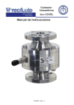
1
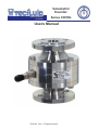
Volumetric
Counter
instrumentation
for fluids
Series COVOL
Users Manual
R-MI-05 Rev.: 3 English version
INDICE
1
WORKING PRINCIPLE ..........................................................................
3
2
OPERATION ...........................................................................................
3
3
RECEPTION ...........................................................................................
4
4
INSTALLATION .....................................................................................
4
4.1
Mechanical installation .............................................................
4
4.2
Electrical installation ……………..............................................
5
5
OPERATION ..........................................................................................
7
6
MAINTENANCE .....................................................................................
7
6.1
Mechanical part .........................................................................
7
6.2
Disassembly ………...............................….…....………….........
8
6.3
Mounting ………….....................................………………..........
8
6.4
Electrical part ............................................................................
9
6.5
Error detection diagram …..……................…..…………..........
10
7
MATERIALS ...………….........................................................................
11
8
TECHNICAL CHARACTERISTICS .......................................................
12
Dimensions ...............................................................................
13
8.1
2
1
WORKING PRINCIPLE
Via rotary oscillating piston and annular metering chamber.
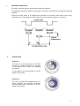
The drawings show the rotation of the piston, moved by the fluid flow through the metering
chamber.
Inside the piston there is a magnet that activates an external reed switch once every
complete cycle. The signal from the reed switch is the input to electronic counters.
2
OPERATION
Position 1
The flow of a liquid through the COVOL
volumetric counter exercises a pressure
on the piston which starts the metering
movement.
In this position the liquid starts to fill the
inside of the piston.
Position 2
The entry of liquid fills progressively the
space between the counter’s chamber
and the piston and continues to fill the
inside of the piston.
3
Position 3
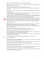
In this point the inside of the piston has
been completely filled and the outside
chamber continues to be filled.
Position 4
The inside of the piston starts to
empty. The outside chamber continues
to be filled. Also the inside of the piston
starts to be filled again.
From this point the piston repeats the cycle, moving a constant volume of liquid for each
cycle, progressively opening and closing the inlet and outlet of the metering chamber.
3
RECEPTION
COVOL volumetric counters are supplied individually packaged for protection during
transport and storage.
All auxiliary equipment that may be ordered is supplied in the same conditions.
All equipment has been tested and is ready to use once it is mounted and wired according to
these instructions.
4
INSTALLATION
4.1
Mechanical installation
It does not need straight sections of pipe and can be installed immediately before or after
regulation or fast closing valves.
The position of the counter can be indistinctly vertical or horizontal or inclined. The flow
direction does not have any influence on the precision of the COVOL.
You must always be sure that the pipes are full of liquid and free of air.
If there is any possibility of an air intake in the installation, an air extractor should be installed
before the counter.
A filter must be installed before the COVOL to guarantee correct performance and avoid
expensive damage.
The mesh filter should have 0,1 to 0,2 mm2 pitch to avoid big particles that may block or
encrust in the rotating piston and act as a break by rubbing, producing errors in the flow or
volume readings.
Observations
The high repeatability of volumetric transmission for each piston revolution can be affected by
incorrect installation. The following are the consequences of bad installation and the cause.
4
OBSTRUCTION OR FRICTION OF THE PISTON BY PARTICLES
Normally caused by the absence of a filter or perhaps the mesh size is bigger than the
recommended ( 0.1 to 0.2 mm2 ).
AIR POCKETS. THE COUNT IS HIGHER THAN REAL VOLUME.
Usually due to excessive emptying of storage tanks. The minimum level should be
controlled.
Provide venting in cases of possible air inlets. These should be mounted before the counter.
CAVITATIONS
Avoid the installation of a COVOL counter in low pressure zones, for example in suction side
of pumps or in down-flowing discharge pipes with a free outlet.
In these cases, the air pockets that could reach the counter, due to inadequate pipe
installation or those formed by cavitations, will give false readings. Specifically, the electronic
device associated with the meter will indicate a volume greater than real.
For the correct working of COVOL counters, one should follow the API 2534 norm which
states that at the outlet of counters there should be a pressure higher than twice the counter
pressure drop (in the case of COVOL this pressure drop is 3 m H2O or 0.3 bar at maximum
flow rate), plus 1.25 times the vapour pressure of the liquid or its most volatile component.
VOLUME VARIATION
Pipe lengths that behave in different ways in each filling operation of reactors or open tanks.
One must make sure that the pipes always work as a FULL pipe or an EMPTY pipe.
EMPTY pipe. The continuity of the pipe is broken after the counter by the use of a funnel and
posterior discharge pipe.
FULL pipe. The discharge pipe is above the level of the counter.
By means of a fast closing valve installed at the outlet of the discharge pipe.
This possibility is valid only when only one product is measured
When it is necessary to count several products using only one counter, fast closing valves
must be installed in each pipe, just before the collector inlet.
It is important to take into account all the conditions we have indicated for EMPTY pipes,
CAVITATIONS or AIR POCKETS.
It is recommended to use the last product as the cleaning element of the counter.
4.2
Electrical Installation
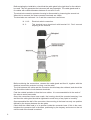
The COVOL counter has a detector for the rotary piston, which closes an electrical
contact once for every turn of the piston.
The external part of the detector is fastened to the counter by 4 screws. The connector
consists of 3 parts joined by threaded nuts. (See figure on next page).
Loosening the larger nut in the middle of the connector allows us to withdraw the half
where later the cable will be soldered.
The other half of the connector is fixed to the counter and should not be removed, except
when servicing the detector (See point 6.4 of the MAINTENANCE section).
The part of the connector we have removed consists of the cable gland at the top and the
electrical connection protector housing.
5
Before starting the installation, check that the cable gland is the right size for the cable to
be used. This will guarantee the instrument will stay watertight. The cable gland used is
for cables with outside diameters between 6 mm and 10 mm.
The electrical connection protector housing is dismounted by loosening the second nut.
When this is removed, the three connector terminals are visible.
The terminals are numbered 1 to 3 and the connection is as follows:
N. 1 & 2:
Electrical switch connection.
N. 3:
This terminal has a shortcircuit with terminal N.1. Don’t connect
anything to this terminal.
Before soldering the connections, unscrew the cable gland and feed it, together with the
electrical connection protector housing, over the cable.
The joint between the cable and the connector should always be soldered, and should be
tidy and without short circuits between terminals.
Peel the outside insulation to free the inner cables. It is recommended to tin the ends of
the wires to avoid loose ends.
Once the connections have been made, the housing should be mounted screwing it on
and then the cable gland should be tightened to avoid entry of any liquid or humidity.
Once assembled the half of the connector, the mounting in the base has only one position
defined by the keyway between the two parts.
Check that the rubber seal is in its position inside the connector base. If this is the case,
introduce the connector half in the base, positioning by the keyway, and screw on the nut
until the end of the thread is reached.
6
NOTE: It is important that the installation of the cable between the COVOL counter and
the electronic counters is made in zones where there are no high voltage or power cables.
In the event that these cables are present, they should be kept at least 5 cm away from
the COVOL counter cable.
5
OPERATION
The oscillating rotating piston of COVOL's mechanic system, allows volume readings with
better than ± 0,8% precision in correct installations.
Each piston revolution inside the metering chamber, transmits a constant volume depending
of the characteristics of the fluid.
The recommended operation maximum and minimum flow rates for each DN are:
DN
MINIMUM FLOW
RATE
l/h
MAXIMUM FLOW
RATE
m³/h
MAXIMUM INTERMITTENT
FLOW RATE
m³/h
10 G1/4”
10
15
25
40
50
80
100
8
20
60
100
200
400
600
800
0.250
0.350
1.5
4.5
8.5
16
28
60
0.5
0.8
2.7
9
15.5
28
50
104
In the case of exceeding the maximum flow rate for a prolonged period of time, it could
damage the rotating piston inside the COVOL.
The pressure drop at maximum flow rate for all models is 3 m H2O (0,3 bar) for water at
20ºC.
6
MAINTENANCE
6.1
Mechanical part
In normal working conditions the COVOL counter has a long life. Normally it will not be
necessary to change any parts.
The life of the parts depends mainly on the abrasive characteristics of the product to be
measured and the flow rate.
The combination of these two factors, together with the construction material of the counter,
make it difficult to estimate the life of the counter in good working conditions
NOTE: If the maximum flow rate for each DN shown in the table is exceeded the life of the
pieces can be considerably reduced.
The maintenance of the COVOL counter in normal installations is practically null due to
the simple construction.
7
6.2
Disassembly
The equipment consists of the following elements:
- THREADED PIPE FITTINGS OR FLANGES (CUPS)
- COUNTER BODY (Central body and Input/Output Chamber )
- ROTARY PISTON
- PRODUCT INPUT/OUTPUT SEPARATOR
- METERING CHAMBER GUIDE DISK (two)
THREADED PIPE FITTINGS OR FLANGES (CUPS)
The threaded pipe fittings or flanges (cups), do not require any type of maintenance
except the routine cleaning.
COUNTER BODY.
The central ring of the counter is the metering chamber in which the rotary piston turns,
moving a constant volume for each cycle.
It can only be deteriorated by abrasive products, or unfiltered hard particles, that scratch
the inside wall of the metering chamber, or incrust in the piston.
If the effect is important, the metering chamber must be touched up in out workshops and
then adjusted with a new rotary piston.
The disassembly of the body should be started at the side marked with the number 2, and
this is done by loosening the hexagonal bolts situated on the periphery of the cups and
central ring of the counter.
Once loosened and removed (it only has to be done on the N. 2 side of the counter), we
can detach the cup. The O ring and the smooth exterior part of the metering chamber's
disk can now be seen.
The disk has a threaded hole that takes a screw to allow us to withdraw the disk smoothly.
The disk should be withdrawn perpendicularly, uncovering the metering chamber with the
rotary piston and input/outlet separator.
The piston is easily removed and it has a drop form opening into which the input/outlet
separator is fitted which acts as guide for the rotation of the piston.
The input/outlet separator joins the metering chamber ring to the central circular guide of
the guide disk.
It is extracted by pulling it out perpendicularly.
In this way the metering chamber is completely dismounted for inspection and thorough
cleaning if necessary
ROTARY PISTON
This is the only mobile piece of the COVOL counter.
It has a long life due to the Teflon and graphite composition, that makes it very wear
resistant and gives it a low friction coefficient.
Premature wear can only be due to abrasive products and flow rate higher than those
indicated in the table of page 7, which provoke excessive knocks at the inflection point of
the oscillating turning of the piston, producing breakage at very high speeds. Other
materials for the piston can be used depending on the application without affecting
significantly its working life.
6.3
Mounting
If the counter body has been completely dismantled, reassembly should start with the cup
Nº 1. For this, one cup, the corresponding O ring and the guide disk, with the body rings
towards the inside of the metering chamber, starting with the number 1.
8
The counter body (central ring) is assembled and the fixing screws are mounted around
the edge, they are tightened until a rigid assembly is obtained (the final tightening will be
done later).
The input/output separator is fitted with the bevelled part in the groove of the guide disk
rings and the part with sharp edges in the groove of counter ring.
The piston is mounted taking care that the drop form opening fits over the input/output
separator and that the piston shaft fits into the circular groove formed by the two rings of
the guide disk. Check that the piston rotates smoothly without rubbing in its complete
path.
With the help of the extractor screw that we have mounted during disassembly, mount the
guide disk with the flat side outwards, coupling the key seat in it’s position.
Note that the guide disk Nº 2 HAS ITS MOUNTING POSITION DEFINED by the groove
for the input/output separator (on Nº 1 side the guide disk is positioned by a hole that fits
over a pin).
These two elements indicate the mounting position which should be made to coincide
exactly.
If this is not done as indicated, the guide disk could be damaged and also a hermetic
sealing of the counter will not be obtained.
Check the perfect fitting of the guide disk, place the O ring on the guide disk and adjust it
around the edge of the counter ring.
Mount the cup or coupling piece, checking the position of the O ring. Assemble the fixing
screws and tighten them until the two pieces are firmly against each other.
Tighten the screws of the other cup.
The counter is ready for installation and operation.
6.4
Electrical part
THE REED OR DETECTOR of the rotating piston revolutions is mounted exteriorly in the
central ring of COVOL counter body.
The maximum working temperature is 150ºC.
It is fixed by 4 screws to the counter body and exteriorly consists on the cable connector, the
connector base and the rubber glands. On the inside it has a terminal block and a reed
switch.
The cable connector, as explained previously, can be dismounted using the larger nut to
separate it from the base.
The rest of the assembly is dismounted by loosening the 4 M3 screws and removing it
from the counter body.
It is advisable to remove the complete assembly, including the rubber seals.
In the event of breakage of the reed switch, it can be replaced by loosening the lower
screws of the terminal block.
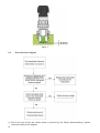
The mounting of the reed switch on the counter should be done as shown in Fig 1, taking
into account THE POSITION OF THE REED SWITCH IN THE GROOVE, located in the
bottom of the housing.
It is also important that the space between the reed switch and the body of the flow meter
is not greater than 2 mm, as shown in Fig 1, otherwise the reed switch may not be
activated by the magnet in the interior piston.
Taking into account the previous, the mounting of the assembly is made by assembling
the pieces and positioning it in the seating in the body. The assembly is fixed by the 4 M-3
screws, tightened until the resistance of the seal is noted.
9
figure 1
6.5
Error detection diagram
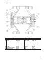
(1) First of all, may be that the rotative piston is jammed by dirt. Before disassembling it please
check according to the diagram.
10
7
MATERIALS
N.
1
2
3
4
5
6
8
9
10
11
12
Component
Input / Output Chamber
O-ring
Guide disk
Piston
Connector
Flat gasket
Reed Switch
Flanges
Screws
Input / Output separator
Metering chamber
AISI-316
AISI-316
NBR / Viton
AISI-316
PTFE-Graphite, Al, etc
Brass / Plastic
NBR
Glass 0,3 A-220V
Steel / AISI-316
AISI-304
AISI-316
AISI-316
PTFE
PTFE
Viton / PTFE
PTFE
PTFE-Graphite
Brass / Plastic
NBR
Glass 0,3 A-220V
Steel / PTFE
AISI-304
PTFE
PTFE
PVC / PP
PVC / PP
NBR / Viton
PVC / PP
PTFE-Graphite
Brass / Plastic
NBR
Glass 0,3 A-220V
Steel-PVC / PP
AISI-304
PTFE
PVC / PP
11
8
TECHNICAL CHARACTERISTICS
x
x
x
x
x
x
x
x
x
x
x
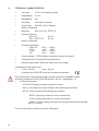
Accuracy:
± 0,8 % of measuring range.
Repeatability:
± 0,3%.
Rangeability:
30:1.
Mounting:
Horizontal or vertical.
Pipe fittings:
DIN 2501 PN 16 Flanges.
Others on demand.
Materials:
AISI-316, PVC, PTFE, PP.
Working Pressure:
- AISI-316:
- PVC / PTFE / PP:
Others on demand.
Working temperature:
- AISI-316:
- PVC:
- PTFE:
- PP:
PN 16
PN 10
-40ºC ... +150ºC.
0ºC ... +40ºC.
-20ºC ... +130ºC.
-10ºC ... +80ºC.
Piston material: PTFE-Graphite, Aluminium, Bronze and others.
Connector IP65. On demand Exd terminal box.
Recommended cable: bifilar with shield over 50 m length.
Características del sensor reed
x
x
V max: 30 VDC.
I max: 20 mA.
Complies with 97/23/CE Directive for pressure equipment.
This equipment is considered as being a pressure accessory and NOT a safety
accessory as defined in the 97/23/CEE directive, Article 1, paragraph 2.1.3.
x
Auxiliary Electronics:
- CIP & CIPII: Battery powered volumetric counter.
- MC-01: Flow rate and volume indicator with batching pre-selection.
- MT-02: Volume counter with batching pre-selection..
- DFD-2: Frequency divider for control instruments.
- CI-420: Analog transmitter for control instruments.
- CP420 / CH420: Analog transmitter with flowrate and volume indicaton.
HARTTM protocol.
For more information consult the specific catalogues.
12
8.1
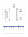
Dimensions
AISI-316
DN
D
k
g
l x n.
B
Flange
PN
A
L
10
90
60
40
14 x 4
14
16
85
180
15
95
65
45
14 x 4
14
16
105
180
25
115
85
68
14 x 4
16
16
140
200
40
150
110
88
18 x 4
16
16
180
220
50
165
125
102
18 x 4
18
16
200
240
80
200
160
138
18 x 8
20
16
250
260
100
220
180
158
18 x 8
20
16
360
340
13
PVC, PTFE, PP
14
DN
D
k
g
l x n.
B
Flange
PN
A
L
10
90
60
40
14 x 4
14
10
125
210
15
95
65
45
14 x 4
14
10
140
210
25
115
85
68
14 x 4
16
10
170
230
40
150
110
88
18 x 4
16
10
200
250
50
165
125
102
18 x 4
18
10
230
270
80
200
160
138
18 x 8
20
10
290
330
100
220
180
158
18 x 8
20
10
420
450
APPLICATIONS
MOUNTING
Filling tanks
Counter and electro valve
in the working area
Volume batching
Counter in storage area and
electro valve in working area
Measuring condensed vapour
and fuel consumption
Closed Valve
Venting
Condensate
Boiler
Open Valve
Burner
Fuel
15
WARRANTY
TECFLUID guarantees all the products for a period of 24 months from their sale, against all
faulty materials, manufacturing or performance. This warranty does not cover failures which
might be imputed to misuse, use in an application different to that specified in the order, the
result of service or modification carried out by personnel not authorized by Tecfluid, wrong
handling or accident.
This warranty is limited to cover the replacement or repair of the defective parts which have not
damaged due to misuse, being excluded all responsibility due to any other damage or the
effects of wear caused by the normal use of the devices.
Any consignment of devices for repair must observe a procedure which can be consulted in the
website www.tecfluid.fr, "After-Sales" section.
All materials sent to our factory must be correctly packaged, clean and completely exempt of
any liquid, grease or toxic substances.
The devices sent for repair must enclose the corresponding form, which can be filled in via
website from the same "After-Sales" section.
Warranty for repaired or replaced components applies 6 months from repair or replacement
date. Anyway, the warranty period will last at least until the initial supply warranty period is
over.
TRANSPORTATION
All consignments from the Buyer to the Seller's installations for their credit, repair or
replacement must always be done at freight cost paid unless previous agreement.
The Seller will not accept any responsibility for possible damages caused on the devices during
transportation.
TECFLUID
B.P. 27709
95046 CERGY PONTOISE CEDEX - FRANCE
Tel. 00 33 1 34 64 38 00 - Fax. 00 33 1 30 37 96 86
E-mail: [email protected]
Internet: www.tecfluid.fr
The technical data in this document is subject to modification without notification, if the technical innovations in the product or
manufacturing processes so require.