1
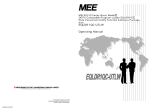
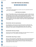
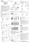
 SAFETY PRECAUTIONS (Always read these precautions prior to use.)
Before using this product, please read this manual and the relevant manuals introduced in this manual
carefully and pay full attention to safety to ensure that the product is used correctly.
The precautions presented in this manual are concerned with this product only. For PLC system safety
precautions, refer to the CPU module user’s manual.
In this manual, the safety precautions are ranked as “DANGER” and “CAUTION.”
DANGER
CAUTION
Note that failure to observe the
Indicates that incorrect handling may cause hazardous conditions,
resulting in death or severe injury.
Indicates that incorrect handling may cause hazardous conditions,
resulting in medium or minor injury and/or property damage.
CAUTION level instructions may lead to a serious consequence
according to circumstances. Always follow the precautions of both levels because they are important to
personal safety.
Please keep this manual in an easy-to-access location for future reference, and be sure to provide the manual
to the end user.
[HANDLING PRECAUTIONS]
DANGER
The 0.31A current consumption of EQLDR01 is supplied from the power supply module of the main
base unit. Prior to connecting EQLDR01, verify that the output current of the power supply module
is sufficient. If it is not, the PLC will stop operation and all outputs will turn off.
CAUTION
Do not mount or remove the Compact Flash card with the product connected to the QCPU (power
ON). Doing so could lead to product or Compact Flash card malfunction or failure.
When connecting the product to the QCPU, hold the connector section of the RS-232 cable. Failure
to do so could lead to product or QCPU failure.
Do not disassemble or modify the product. Doing so could lead to failure or injury.
[DISPOSAL PRECAUTIONS]
CAUTION
A-1
When disposing of the product, treat it as industrial waste.
A-1
REVISIONS
*The manual number is given on the bottom left of the back cover.
Print Date
*Manual Number
Oct., 2005
50EM8508-A
Revision
First Edition
This manual confers no industrial property rights or any rights of any other kind, nor does it confer any patent licenses.
Mitsubishi Electric Engineering Company Limited cannot be held responsible for any problems involving industrial
property rights which may occur as a result of using the contents noted in this manual.
© 2005 MITSUBISHI ELECTRIC ENGINEERING COMPANY LIMITED
A-2
A-2
INTRODUCTION
Thank you for purchasing the EQLDR01 Program Loader manufactured by Mitsubishi Electric Engineering
Company Limited (hereinafter referred to as “MEE”).
Prior to use, please read this manual carefully to develop full familiarity with the functions and performance of
this product, so as to ensure correct use.
TABLE OF CONTENTS
SAFETY PRECAUTIONS..........................................................................................................................A-1
REVISIONS ...............................................................................................................................................A-2
INTRODUCTION .......................................................................................................................................A-3
TABLE OF CONTENTS.............................................................................................................................A-3
1.
OVERVIEW ................................................................................................................................1-1 to 1-1
1.1
Features .......................................................................................................................................... 1-1
1.2
Functions ......................................................................................................................................... 1-1
2.
SYSTEM CONFIGURATION......................................................................................................2-1 to 2-1
3.
SPECIFICATIONS......................................................................................................................3-1 to 3-2
3.1
General Specifications .................................................................................................................... 3-1
3.2
Performance Specifications............................................................................................................. 3-2
3.3
Target Data ...................................................................................................................................... 3-2
4.
PART NAMES AND FUNCTIONS .............................................................................................4-1 to 4-3
5.
USING PROGRAM LOADER ....................................................................................................5-1 to 5-2
5.1
Operation Procedure ....................................................................................................................... 5-1
5.2
Mounting and Removing the Compact Flash Card ......................................................................... 5-2
5.3
Password......................................................................................................................................... 5-2
6.
ERROR CODES.........................................................................................................................6-1 to 6-2
7.
EXTERNAL DIMENSIONS ........................................................................................................7-1 to-7-1
A-3
A-3
1. OVERVIEW
1. OVERVIEW
This manual describes the EQLDR01 Program Loader (hereinafter referred to as
“Program Loader”) which connects to a Mitsubishi PLC MELSEC Q Series basic model
QCPU, allowing you to batch-read and batch-write programs and other data.
1.1
Features
(1)
Easy to Operate
Program Loader allows you to simply batch-read and batch-write CPU data, such as
programs and parameters, by operating two buttons.
(2)
Batch Reading/Writing of All CPU Data
Program Loader can batch-read and batch-write all data on all drives (program
memory, standard RAM and standard ROM) of a single CPU, excluding device
memory. The data can be saved in the built-in memory of Program Loader. (The
data does not disappear even when the power is turned off.)
(3)
Use of Compact Flash Cards
A Compact Flash card can be used for storing data and transferring data to and
from Program Loader. A Compact Flash card formatted by Program Loader (the
product) can also be used. One Compact Flash card can store the data of one CPU.
1.2
Functions
Program Loader offers the following functions:
*1
[1]
Batch-write data to CPU (CPU WR mode)
[2]
Batch-read data from CPU (CPU RD mode)
[3]
Copy data from internal memory to Compact Flash card (MEM → CF mode)
[4]
Copy data from Compact Flash card to internal memory (CF → MEM mode)
[5]
Clear all internal memory data (MEM CLR mode)
[6]
Format Compact Flash card (CF CLR mode)
*2
*1: When the Compact Flash card is not mounted, the internal memory is the write
source. When the Compact Flash card is mounted, the Compact Flash card is the
write source.
*2: When the Compact Flash card is not mounted, the internal memory is the read
destination. When the Compact Flash card is mounted, the Compact Flash card is
the read destination.
1-1
1-1
2. SYSTEM CONFIGURATION
2. SYSTEM CONFIGURATION
Basic model QCPU
(Q00J/Q00/Q01CPU)
EQLDR01
EQLDR01
PO
POWE
WER
R
MEM.
MEM.
MEM
.
CP
CPU
UW
WR
R
C
F
C
F
C
CPU
PURD
RD
CF
CFWR
WR
C
CF
FR
RD
D
M
ME
EM
M.
.C
CL
LR
R.
.
C
CF
FC
CL
LR
R.
.
M
MO
OD
DE
E
S
ST
TA
AT
TU
US
S
Program Loader
ER
ERR
R.N
.NO.
O.
E
EX
XE
E.
.
C
CF
FCAR
CARD
D
P
U
L
L
P
U
L
L
Compact Flash card
Program Loader allows you to use one storage card (Type I)
TM
that is compliant with Compact Flash
specifications.
Use the card for data storage as necessary.
POINT
•
The Compact Flash card must be formatted (CF
CLR) by Program Loader in advance.
•
The data loaded onto a Compact Flash card is
Program Loader dedicated data. It cannot be read
using GX Developer. In addition, data written on a
Compact Flash card using GX Developer cannot be
written to a CPU using Program Loader.
2-1
2-1
3. SPECIFICATIONS
3. SPECIFICATIONS
3.1
General Specifications
Item
Specifications
Operating ambient
temperature
Storage ambient
temperature
Operating ambient
humidity
Storage ambient
humidity
0 to 55°C
-25 to 75°C
5 to 95% RH, non-condensing
5 to 95% RH, non-condensing
Frequency
Amplitude
-
0.075mm
Under
10 to 57Hz
intermittent
JIS B 3502,
vibration 57 to 150Hz
IEC 61131-2
Under
10 to 57Hz
compliant
continuous
vibration 57 to 150Hz
Vibration
resistance
Shock resistance
9.8m/s
2
-
0.035mm
4.9m/s
2
-
Sweep Count
10 times each
in X, Y, Z
directions
(for 80 min.)
2
JIS B 3502, IEC 61131-2 compliant (147m/s , 3 times each in X, Y, Z directions)
Operating
atmosphere
No corrosive gases
Operating altitude
Overvoltage
*1
category
2,000m or less
*3
II or less
*2
Pollution level
Cooling method
*1.
Acceleration
2 or less
Natural cooling
This indicates the section of the power supply to which the equipment is assumed to be connected
between the public electrical power distribution network and the machinery within premises. Category II
applies to equipment for which electrical power is supplied from fixed facilities. The surge voltage
withstand level for up to the rated voltage of 300V is 2500V.
*2.
This index indicates the degree to which conductive material is generated in the environment where the
equipment is used. In pollution level 2, only non-conductive pollution occurs for temporary conductivity
may be produced due to condensing.
*3.
3-1
The product cannot be used under pressure higher than the atmospheric pressure of altitude 0m.
3-1
3. SPECIFICATIONS
3.2
Performance Specifications
Item
Specifications
Connection method
Transfer speed
External
Cable length
interface Compact Power supply voltage
Flash
Card size
card
Maximum number mounted
Power supply
Current consumption (5V DC)
Weight
External dimensions (excluding cable)
Cable integral with unit
115.2Kbps
0.2m
3.3V DC ± 5%
TYPE I
1 card
From CPU (5V DC)
0.31A
140g
110mm (H) x 75mm (W) x 27.5mm (D)
CPU Type
Q00JCPU Q00CPU
QCPU
RS-232
Mode
Maximum processing time in each mode
(with data in all areas of all drives)
3.3
Q01CPU
Internal memory About 37s
About 93s
CPU WR Compact Flash
About 36s
About 96s
card
Internal memory About 24s
About 58s
CPU RD Compact Flash
About 21s
About 54s
card
MEM.→CF
About 2s
About 3s
CF→MEM.
About 5s
About 7s
MEM. CLR.
About 6s
About
2s
(processing
time differs
*
CF CLR.
according to capacity)
*: With a Compact Flash card capacity of 32MB
Target Data
Program Loader can be used to read and write all data of all drives (program memory,
standard RAM, standard ROM), excluding device memory.
[Batch-read from CPU]
The data of only one CPU can be loaded onto Program Loader (internal memory (MEM.)
or a Compact Flash card).
Since the data of multiple CPUs cannot be loaded onto Program Loader (internal memory
(MEM.) or a Compact Flash card), it is necessary to clear the memory or Compact Flash
card data using the
MEM. CLR. or CF CLR. button before loading the data of another CPU.
[Batch-write to CPU]
Program Loader allows you to replace all CPU data. (The CPU data prior to writing will not
remain.)
3-2
3-2
4. PART NAMES AND FUNCTIONS
4. PART NAMES AND FUNCTIONS
7
EQLDR01
1
POWER
2
MEM.
CF
CPU WR
CPU RD
MEM.→
MEM.→CF
CF→
CF→MEM.
MEM. CLR.
CF CLR.
3
5
MODE
STATUS
ERR.NO.
EXE .
4
6
CF CARD
PULL
10
<⑩ With Compact Flash card opened>
8
4-1
9
4-1
4. PART NAMES AND FUNCTIONS
No.
Name
Description
①
Power LED
•
②
Valid data LEDs
•
③
Mode LEDs
•
*
4-2
Indicates the status of the unit.
<POWER>
On (green) : Power supplied, unit normal
On (red)
: Power supplied, unit error
Off
: Power not supplied (or unit error)
Indicates the existence or nonexistence of valid data and the error
status.
<MEM.>
On (green) : Valid data in internal memory
On (red)
: Internal memory error, internal memory mode
execution error
Off
: No valid data in internal memory
<CF>
On (green) : Valid data on Compact Flash card
On (red)
: Compact Flash card error, Compact Flash card mode
execution error
Off
: No valid data on Compact Flash card (or Compact
Flash card not mounted)
Indicates the selected mode and execution status.
On (green) : Mode selected, execution complete
On (red)
: Error occurred (for CPU WR and CPU RD only)
Off
: Mode not selected
Flickering (green):
Mode execution in progress [Flicker time: 0.5s interval
(on/flicker: 1s)]
The mode switches each time the mode button ⑤ is pressed.
Not selected (including at power on)
↓
<CPU WR>
: Writes data located inside Program Loader (on
the Compact Flash card or in internal memory*)
to the CPU.
↓
<CPU RD>
: Loads data from the CPU to Program Loader (to
the Compact Flash card or internal memory*).
↓
<MEM.→CF> : Copies data from internal memory to the
Compact Flash card.
↓
<CF→MEM.> : Copies data from the Compact Flash card to
internal memory.
↓
<MEM. CLR.> : Clears the data in internal memory.
↓
<CF CLR.>
: Formats the Compact Flash card (clears all
data).
The target data is the data on the Compact Flash card when a Compact
Flash card is mounted, or the data in internal memory when a Compact
Flash card is not mounted.
4-2
4. PART NAMES AND FUNCTIONS
No.
④
Name
Status LEDs
Description
•
⑤
Mode button
•
⑥
Execution button
•
⑦
QCPU cable
•
⑧
Compact Flash card •
interface
Compact Flash card •
eject button
Compact Flash card •
cover
⑨
⑩
4-3
Indicates mode execution results.
<STATUS>
On (green) : Ended successfully.
On (red)
: Ended in error.
Off
: Execution not completed.
<ERR. NO.> (Red)
None
: No error
Other
: Indicates the error details. (For details, refer to Section
6, “Error Codes.”)
The display appears as follows:
0
1
2
3
4
5
6
7
8
9
A
B
C
D
E
F
H
L
P
U
Switches the mode each time the button is pressed.
Clears the displays of ③ and ④ when pressed again after a mode
has been executed, regardless of the error status. (Changes the mode
selection status to not selected.)
Executes the mode selected by mode button ⑤.
Executes the process when held down for two seconds or more.
Note that the button is only valid when the Status LED ④ is off.
A cable for connecting the unit to the QCPU RS-232 interface.
The cable can be stored in the back of the unit.
The interface for mounting the Compact Flash card.
A button for ejecting the Compact Flash card.
A cover for the interface used to mount the Compact Flash card.
Can be closed even with the Compact Flash card mounted.
4-3
5. USING PROGRAM LOADER
5. USING PROGRAM LOADER
5.1
Operation Procedure
Mount a Compact Flash card if necessary.
................Refer to Section 5.2.
Connect Program Loader to the QCPU. ..............................Carefully check the orientation before connection.
POWER on (green)
・STATUS flickering (green)
・The software version flickers in the ERR. NO. LED location.
3 to 8s
Self-diagnosis
Error
Results
・POWER on (red)
・STATUS on (red)
Normal
STATUS on (green)
Point
MODE
(Write to CPU)
CPU WR on (green)
MODE
CPU RD flickering (green)
EXE.
When a Compact Flash card is not mounted, the
CPU data is written to internal memory. When a
Compact Flash card is mounted, the CPU data is
written to the Compact Flash card.
MEM.→ CF flickering
(green)
EXE.
CF→ MEM. flickering
(green)
(Clear internal memory data)
CF CLR on (green)
MODE
EXE.
(Copy Compact Flash card data to internal memory)
CF→MEM. on (green)
MODE
Point
(Copy internal memory data to the Compact Flash card)
MEM.→ CF on (green)
MODE
CPU WR flickering (green)
(Read from CPU)
CPU RD on (green)
MODE
EXE.
When a Compact Flash card is not mounted, the
data of internal memory is written to the CPU. When
a Compact Flash card is mounted, the data of the
Compact Flash card is written to the CPU.
EXE.
Results
Error
Normal
・STATUS: Green
・ERR. No.: No display
・STATUS : Red
・ERR. No. : Displays the error
code. For details, refer
to Section 6, "Error
Codes."
MEM. CLR flickering (green)
[Format Compact Flash card (clear all data)]
CF CLR. on (green)
EXE.
CF CLR. flickering (green)
MODE
MODE, STATUS, ERR. NO.: All off
Remove Program Loader from the CPU.
Eject the Compact Flash card. ................Refer to Section 5.2.
5-1
5-1
5. USING PROGRAM LOADER
5.2
Mounting and Removing the Compact Flash Card
Use a Compact Flash card as needed.
CAUTION
•
Mount and remove the Compact Flash card with the Power Loader disconnected from
the CPU (power OFF).
(1)
Mounting the Compact Flash Card
Pull the PULL section toward you using your finger and open the cover.
↓
Insert the Compact Flash card with the tab down. Fully insert the Compact Flash card until the
Compact Flash card height is the same as that of the EJECT button.
PULL
Compact Flash
EJECT button
card (tab)
↓
Close the cover.
(2)
Removing the Compact Flash Card
Pull the PULL section toward you using your finger and open the cover.
↓
Press the EJECT button and remove the Compact Flash card.
PULL
↓
Close the cover.
5.3
Password
If a password is set on the CPU, Program Loader operates as follows to ensure data protection.
•
Write to CPU (CPU WR)
: Program Loader cannot write to a CPU in which a
password is set.
•
Read from CPU (CPU RD) : Program Loader cannot read data from a CPU in
which a password is set.
5-2
5-2
6. ERROR CODES
6. ERROR CODES
If a mode process ends in error (the “STATUS” LED turns red), the detailed cause of the
error (the error code) will appear on the “ERR. NO.” LED.
Red LED
Error ERR.
other than
Name No.
STATUS
Hardware error
POWER
POWER
CF
0
CPU WR
CPU RD
Password
error
Communication error
1
6-1
CPU WR
CPU RD
2
CPU WR
3
CPU WR
4
CPU WR
5
CPU RD
CPU WR
6
CPU RD
Mode
Cause of Error
Action
Reconnect Program Loader to the CPU
once again.
A memory check error occurred
If the error still exists after performing the
POWER ON
due to a memory error.
above action, please contact the location
in which you made your purchase.
Disconnect Program Loader from the
CPU, remove and reinsert the Compact
Flash card while the power is off, and
The Compact Flash card was
CF card
then reconnect Program Loader.
removal and removed and inserted with the
If the error still exists after performing the
power on.
insertion
above action, please contact the location
in which you made your purchase.
•
Once the CPU reset status has been
•
The CPU was reset.
cleared, reconnect Program Loader.
CPU WR
•
Program Loader was
•
Connect Program Loader to a basic
connected to a noncompliant
model QCPU.
QCPU [QCPU-A (Mode A)].
•
A communication (timeout)
If the error still exists after performing the
error occurred due to a cable above actions, please contact the
CPU RD
error.
location in which you made your
purchase.
Program Loader was connected
CPU WR
Connect Program Loader to a basic
to a noncompliant QCPU
model QCPU.
CPU RD
[excluding QCPU-A (Mode A)].
The write data and connected
Connect Program Loader to the same
CPU WR
CPU type do not match.
CPU as the write data.
The CPU is in a RUN state.
Change the status of the CPU to STOP.
CPU WR
Writing is not possible.
An attempt was made to write
Connect Program Loader to a compliant
CPU WR
SFC program/device initial values
version of the basic model QCPU.
to a Ver. A basic model QCPU.
•
Check the data of the CPU.
Either the CPU data is faulty or
•
Connect Program Loader to a CPU
CPU RD
nonexistent.
in which data exists.
A password is set for the CPU
CPU WR
data. Writing is not possible.
Remove the password of the CPU using
another peripheral device.
A password is set for the CPU
CPU RD
data. Reading is not possible.
6-1
6. ERROR CODES
Red LED
Error ERR.
other than
Name No.
STATUS
Mode
Cause of Error
Internal memory error
Compact Flash card error
•
6-2
7
CF
CPU WR
CF→MEM.
8
CF
CPU RD
MEM. →CF
9
CF
A
CF
b
CF
C
MEM.
CPU RD
MEM. →CF
CPU WR
CF→MEM.
MEM.→CF
CF→MEM.
CF CLR.
CPU WR
MEM.→CF
The Compact Flash card data
is faulty.
•
Program Loader failed to
read from the CF card.
•
There is not enough space on
the Compact Flash card.
(Either the power was turned
off during formatting or other
data exists on the card.)
•
Program Loader failed to
write to the Compact Flash
card.
Data already exists on the
Compact Flash card.
There is no data on the Compact
Flash card.
Action
Format (CF CLR.) the Compact Flash
card and then write the data to the
Compact Flash card.
Format (CF CLR.) the Compact Flash
card.
Write the data to the Compact Flash
card.
The Compact Flash card is not
mounted.
Mount the Compact Flash card.
The internal memory data is faulty.
Clear (MEM. CLR.) internal memory and
then write the data to internal memory.
•
d
MEM.
E
MEM.
F
MEM.
CPU RD
CF→MEM.
CPU RD
CF→MEM.
CPU WR
MEM.→CF
Data exists in internal
memory. (The power was
turned off during data
clearing.)
•
Program Loader failed to
write to internal memory.
Data already exists in internal
memory.
There is no data in internal
memory.
Clear (MEM. CLR.) the data from internal
memory.
Write the data to internal memory.
6-2
7. EXTERNAL DIMENSIONS
16mm
7. EXTERNAL DIMENSIONS
EQLDR01
POWER
CF
CPUWR
CPURD
MEM.→
→CF
MEM.
CF→
CF→MEM.
MEM. CLR.
CF CLR.
MODE
STATUS
ERR.NO.
EXE.
110mm
MEM.
CF CARD
PULL
75mm
7-1
27.5mm
7-1
Product Warranty Details
Please confirm the following product warranty details prior to product use.
Gratis Warranty Terms and Gratis Warranty Range
If any fault or defect (hereinafter referred to as “Failure”) attributable to Mitsubishi Electric Engineering
Company Limited (hereinafter referred to as “MEE”) should occur within the gratis warranty period, MEE shall
repair the product free of charge via the distributor from whom you made your purchase.
Gratis Warranty Period
The gratis warranty period of this product shall be one (1) year from the date of purchase or delivery to
the designated place.
Note that after manufacture and shipment from MEE, the maximum distribution period shall be six (6)
months, and the gratis warranty period after manufacturing shall be limited to eighteen (18) months.
In addition, the gratis warranty period for repaired products shall not exceed the gratis warranty period
established prior to repair.
Gratis Warranty Range
The gratis warranty range shall be limited to normal use based on the usage conditions, methods and
environment, etc., defined by the terms and precautions, etc., given in the instruction manual, user’s
manual and caution labels on the product.
Warranty Period after Discontinuation of Production
(1)
MEE shall offer product repair services (fee applied) for seven (7) years after production of the product
has been discontinued. Discontinuation of production shall be reported via distributors.
(2)
Product supply (including spare parts) is not possible after production has been discontinued.
Exclusion of Opportunity Loss and Secondary Loss from Warranty Liability
Regardless of the gratis warranty period, MEE shall not be liable for compensation for damages arising from
causes not attributable to MEE, opportunity losses or lost profits incurred by the user due to Failures of MEE
products, damages or secondary damages arising from special circumstances, whether foreseen or
unforeseen by MEE, compensation for accidents, compensation for damages to products other than MEE
products, or compensation for other work carried out by the user.
Changes in Product Specifications
The specifications given in the catalogs, manuals and technical documents are subject to change without
notice.