1
LON System-M Pushbutton
Article no.: MTN881401, MTN881451, MTN881501, MTN881601, MTN881651
User Manual
LON System-M Pushbutton
Content
Directory .........................................................................................................................1
1.
Description.......................................................................................................3
2.
Function ...........................................................................................................3
3.
Mounting ..........................................................................................................3
4.
Remarks ..........................................................................................................4
5.
Technical Data.................................................................................................5
6.
Application .......................................................................................................6
6.1
System requirements.......................................................................................6
6.2
Node Object (LONMARK® profile #0)...............................................................11
6.3
Switch Object (LONMARK® profile #3200).......................................................13
6.4
Scene Panel Object (LONMARK® profile #3250).............................................19
6.5
Occupancy Sensor (LONMARK® profile #1060) ..............................................21
Version: 10.07.09
Subject to modifications
Page 1 of 21
LON System-M Pushbutton
Article no.: MTN881401, MTN881451, MTN881501, MTN881601, MTN881651
Pushbutton 1-gang
Pushbutton 2-gang
Pushbutton 4-gang
Pushbutton 4-gang MF
Pushbutton 4-gang MF-IR
LON System-M
Pushbutton 1-gang
MTN881401
polar white glossy
Pushbutton 2-gang
MTN881451
polar white glossy
Pushbutton 4-gang
MTN881501
polar white glossy
Pushbutton 4-gang MF
(multi-function)
Pushbutton 4-gang MF IR
(multi-function, IR receiver)
MTN881601
polar white glossy
MTN881651
polar white glossy
Version: 10.07.09
Subject to modifications
Page 2 of 21
LON System-M Pushbutton
Article no.: MTN881401, MTN881451, MTN881501, MTN881601, MTN881651
1. Description
•
•
•
•
•
•
Application module for LON network in System-M Design available as 1-, 2-, 4-gang pushbutton.
With 2, 4, or 8 pushbuttons for individually assigned functions
Pushbutton 1-, 2-, 4-gang each have one status LED per pair of buttons
Pushbutton 4-gang MF and pushbutton 4-gang MF-IR each have one status LED per buttons
The application module possesses one operating LED
Software application according to LonMark profile “Switch (3200)”, Scene Panel (3250)”, and
“Occupancy Sensor (1060)” for light, sunblind or scene and occupancy control
2. Function
Via the pushbuttons the application specific functions can be executed.
There are applications available for lighting, blind and scene control.
The operating LED can be switched off via a configuration parameter.
The buttons can be dedicated individually to ten function objects (switch).
Via the Universal Plug-in there is alternatively the possibility to assign the button functions freely to any
object. There is among other things the possibility to configure specific functions according to the push or
loose of the button also in combination with the pressing time. Furthermore it is possible to assign
different functions to the Status- LEDs.
3. Mounting
The application module is plugged onto the LON BCU and completed with a frame.
The LON BCU and the frame have to be ordered separately.
The LON BCU represents the mechanical, electrical and data technical connection between a LON TP/LP
network and the application module.
To prevent the connector of the application module from spoiling, the application module has to be stuck
upright onto the BCU.
Version: 10.07.09
Subject to modifications
Page 3 of 21
LON System-M Pushbutton
Article no.: MTN881401, MTN881451, MTN881501, MTN881601, MTN881651
4. Remarks
Installation and assembly of electrical devices may take place only by an electrical specialist.
When planning and installing an electrical system the relevant standards, guidelines and regulations of
the respective country are to be considered. Beyond that the device specifications are to be kept. For
project engineering, assembly and line-up detailed expertise of the LON technology is presupposed.
The function of the device is software dependent. Only application programs may be loaded, which are
approved for this device.
The system integrator has to carry ensuring that the loaded application program and the configured
parameters in it correspond with the outside wiring of the device. This applies in particular if for different
use several application programs for a device are available.
Version: 10.07.09
Subject to modifications
Page 4 of 21
LON System-M Pushbutton
Article no.: MTN881401, MTN881451, MTN881501, MTN881601, MTN881651
5. Technical Data
Power supply
Power consumption
including BCU (max.):
1 LPUL (285 mW), 6.2 mA @ 42V, 25 mA @ 5V
DC 42.8V (supplied by the network)
Controls, application module
2-8 Operation buttons:
To activate the application specific function
Indicators, application module
LEDs next to the operation buttons:
Operation-LED:
Red: ON-state
Green: ready for operation and online
Site Conditions
Operation temperature:
Protection class :
-5 °C .. +45 °C
IP20
Connections
Physical External Interface (PEI):
10 pole interface (PEI)
Conformity
EU Directive:
Version: 10.07.09
2004/108/EEC
Subject to modifications
Page 5 of 21
LON ARTEC pushbutton
Application: 880451SW12E
6. Application
The application “880451SW12E” (880451SW12E_Schneider.nxe has to be used for the pushbuttons with
multi-function) is for System-M pushbutton application units with LON Bus Coupling Unit, to control LON
devices via the LON network. Thus, light scenes can be enabled just as switch and dim commands for
blinds and lamps can be transmitted. The application contains the LonMark profiles “Switch (3200)“ (10x),
“Scene Panel (3250)“ (1x) and “Occupancy Sensor (1060)“ (1x).
6.1
System requirements
For the configuration of the application a LNS-compatible commissioning tool is needed! All properties are
used as “User-defined Configuration Property Types” (UCPT’s) by Direct-Memory-Access. For use of
these properties, the Device Resource Files” have to be installed before (!) a device template is created.
This application was generated especially for the use with an LNS Version 3.0 or higher.
Function
Switch Object
Configuration of the Switch Object/Push Button Sensor
The Switch Object can be configured in a very flexible way to provide the user the opportunity to meet all
requirements of his project.
By use of the UCPTcmdXXX[i] parameters, messages can be assigned arbitrarily to the outputs
nvoSWswitch[i] and nvoSWsetting[i] for every switching event. By default, the Switch Object is configured
for one-fold switch control. Therefore the names “FirstEvent“ and “SecondEvent“ signify the alternating
switching events at the digital input.
Assigning the switching events to the digital inputs
To assign the switching events to the digital inputs the parameters UCPTbuttonMapFirstEvent[i] and
UCPTbuttonMapSecondEvent[i] are used.
During every switching event, up to four messages can be generated. The commands the messages
contain can be defined individually. If a message shall not be transmitted, the .function element of the
corresponding UCPTcmdXXX[i] parameter has to be set at SET_NO_MESSAGE.
Interpretation of the .function element of UCPTcmdXXX at nvoSWswitch[i]
The parameters UCPTcmdXXX[i] specify the output value of nvoSWsetting[i]. The
nvoSWswitch[i] output is adjusted according to the following scheme:
nvoSWswitch[i].state is adjusted to UCPTcmdXXX[i].function as follows:
.function = SET_ON, SET_UP, SET_DOWN, SET_STATE .state = 1
.function = SET_OFF
.state = 0
.function = SET_NUL
.state = -1
nvoSWswitch[i].value is adjusted to UCPTcmdXXX[i].function as follows:
.function = SET_ON .value = SCPTmaxOut[i] after restart resp.
nviSWswitchFb[i].value
(last value before switching-off)
.function = SET_OFF
.value =
0
.function = SET_UP, SET_DOWN .value =
.value +/- .setting
.function = SET_NUL, SET_STATE .value =
.setting
Version: 10.07.09
Subject to modifications
Page 6 of 21
LON ARTEC pushbutton
Application: 880451SW12E
The Switch Object provides a memory function. If it is switched on by a SET_ON command, the
nvoSWswitch[i] output adopts the last feedback value received.
One-fold switch control
One of the digital inputs initiates the first as well as the second switching event. Therefore,
UCPTbuttonMapFirstEvent[i] as well as UCPTbuttonMapSecondEvent[i] have to be assigned
to this input by setting the corresponding bit = 1.
Switching by push button
If a push button is connected to the digital input, ON and OFF commands shall be transmitted alternately
with every rising edge (e. g. a push at a push button). For this purpose, the parameters have to be
configured as follows:
UCPTcmdPushFirstEvent[i]
UCPTcmdPushSecondEvent[i]
All other UCPTcmdXXX[i]
= {SET_ON; x; x}
= {SET_OFF; x; x}
= {SET_NO_MESSAGE; x; x}
If the output network variable value shall be lowered to a value different from zero, this value has to be
defined in UCPTcmdPushSecondEvent[i].setting in combination with .function = SET_STATE.
If the output network variable value shall be switched with every falling edge (e. g. a push at a break
contact element), values have to be defined in UCPTcmdReleaseFirstEvent[i] and
UCPTcmdReleaseSecondEvent[i], all other UCPTcmdXXX[i] are set at {SET_NO_MESSAGE; x; x}.
Switching/Dimming by digital input / push button
If a push button is used for switching and dimming, the UCPTpressTimeThreshold[i] parameter
defines a time that distinguishes between push and hold of the button.
ON and OFF commands are transmitted alternately with every falling edge that follows a short pulse
(when the button is released after a push). With every long pulse (hold of the button), the dimming level is
raised/lowered alternately.
The fade starts as soon as the press time threshold has been exceeded. The values defined in
UCPTcmdHoldFirstEvent[i] resp. UCPTcmdHoldSecondEvent[i] are transmitted consecutively
until the input is opened again whereas the corresponding .setting element contains the dim step
value. The parameters have to be configured as follows:
UCPTcmdReleaseFirstEvent[i]
UCPTcmdReleaseSecondEvent[i]
UCPTcmdHoldFirstEvent[i]
UCPTcmdHoldSecondEvent[i]
All other UCPTcmdXXX[i]
= {SET_ON; x; x}
= {SET_OFF; x; x}
= {SET_UP; 5 %; x}
= {SET_DOWN, 5 %; x}
= {SET_NO_MESSAGE; x; x}
Two-fold switch control
One of the digital inputs initiates the first switching event. The other input initiates the second. Both inputs
cause always the same command. Therefore the UCPTbuttonMapFirstEvent[i] parameter has to be
assigned to the one input, UCPTbuttonMapSecondEvent[i] to the other by setting the bit
corresponding to the chosen input = 1.
Version: 10.07.09
Subject to modifications
Page 7 of 21
LON ARTEC pushbutton
Application: 880451SW12E
Switching by rocker switch
If a rocker switch is connected to two digital inputs, ON commands shall be transmitted with every rising
edge at the one input and OFF commands shall be transmitted with every rising edge at the other input.
For this purpose, the parameters have to be configured as follows:
= {SET_ON; x; x}
= {SET_OFF; x; x}
= {SET_NO_MESSAGE; x; x}
UCPTcmdPushFirstEvent[i]
UCPTcmdPushSecondEvent[i]
All other UCPTcmdXXX[i]
If the network variable output value shall be switched with every falling edge (e.g. push at a break contact
element), values have to be defined in UCPTcmdReleaseFirstEvent[i] and
UCPTcmdReleaseSecondEvent[i], all other UCPTcmdXXX[i] are set at {SET_NO_MESSAGE; x; x}.
Switching/Dimming by rocker switch
The UCPTpressTimeThreshold[i] parameter defines a time that distinguishes between push and
hold of the button when fades are controlled.
The network variable output value is switched on with every falling edge (that follows a short pulse) at the
one input. It is switched off with every falling edge at the other input.
The dimming level is raised with every long pulse at the one input. It is lowered with every long pulse at
the other input.
The fade starts as soon as the press time threshold has been exceeded. Then, the values defined in
UCPTcmdHoldFirstEvent[i] resp. UCPTcmdHoldSecondEvent[i] are transmitted consecutively
until the input is opened again whereas the corresponding .setting element contains the dim step
value. The SCPTminSendTime[i] parameter defines the minimum period of time between two
consecutive dim commands. The parameters have to be configured as follows:
UCPTcmdReleaseFirstEvent[i]
UCPTcmdReleaseSecondEvent[i]
UCPTcmdHoldFirstEvent[i]
UCPTcmdHoldSecondEvent[i]
All other UCPTcmdXXX[i]
= {SET_ON; x; x}
= {SET_OFF; x; x}
= {SET_UP; 5 %; x}
= {SET_DOWN; 5 %; x}
= {SET_NO_MESSAGE; x; x}
Sunblind Control by rocker switch
For sunblind control, the UCPTpressTimeThreshold[i] parameter defines a time that distinguishes
between push and hold of the button.
The sunblind is raised completely with every rising edge at the one input. It is lowered completely with
every rising edge at the other input. It can be stopped by a falling edge that follows a short pulse (by
releasing the button after a push). For this purpose, the parameters have to be configured as follows:
UCPTcmdPushFirstEvent[i]
UCPTcmdPushSecondEvent[i]
UCPTcmdReleaseFirstEvent[i]
UCPTcmdReleaseSecondEvent[i]
All other UCPTcmdXXX[i]
= {SET_UP; 100 %; x}
= {SET_DOWN; 100 %; x}
= {SET_STOP; x; x}
= {SET_STOP; x; x}
= {SET_NO_MESSAGE; x; x}
The required drive commands may vary according to the used motor control unit.
Version: 10.07.09
Subject to modifications
Page 8 of 21
LON ARTEC pushbutton
Application: 880451SW12E
Scene Panel Object
The UCPTbuttonFslSceneCmd[i] parameter assigns a scene number to a pushbutton. The messages
transmitted by nvoSPscene can be configured individually for every input by use of these configuration
properties.
Recalling scenes
Caused by a short switch pulse (generally initiated by a short push on a make-contact element), a recall
command nvoSPscene.function = SC_RECALL and the scene number of the particular input
nvoSPscene.scene_number = UCPTbuttonFslSceneCmd[i] are transmitted via the nvoSPscene
output. Thus, the scene controller operates the corresponding scene settings. A scene number zero is not
transmitted.
Storing scenes
Caused by a long switch pulse, which exceeds the time threshold defined in the
UCPTsceneLearnDelay property, a learn command nvoSPscene.function = SC_LEARN and the
scene number of the particular input nvoSPscene.scene_number = UCPTbuttonSslSceneCmd[i]
are transmitted. Thus, the current scene settings are stored in the controller memory under the given
scene number.
Occupancy Sensor
All digital inputs can also be used as presence input.
The telegrams to be send at the nvoOSoccupancy can be configured in the parameters
UCPTbuttonRslOccCmd[i] individually for every input.
Button and LED assignments for different applications
The assignments of buttons (B) and LEDs (L, if available) to the several software objects are different
depending on the manufacturer. They could be configured for individual requirements with the parameters
UCPTbuttonMapFirstEvent[i], UCPTbuttonMapSecondEvent[i] and UCPTledMap[i]. The
indices .bitx of the parameters correspond to the indices of the following patterns.
We advise to configure the application with the available LNS Plug-Ins.
Example:
The explanation shows how to configure a LON ARTEC Pushbutton 1-gang to set the buttons to control
the first software object with the index [0].
Default:
1-gang
B
L
6
0
B
1
Version: 10.07.09
UCPTbuttonMapFirstEvent[0]
UCPTbuttonMapSecondEvent[0]
UCPTbuttonMapFirstEvent[6]
UCPTbuttonMapSecondEvent[6]
Subject to modifications
.bit0 = 1, all other .bitx = 0
.bit1 = 1, all other .bitx = 0
.bit6 = 1, all other .bitx = 0
.bit7 = 1, all other .bitx = 0
Page 9 of 21
LON ARTEC pushbutton
Application: 880451SW12E
With the default setting (hardware conditioned), the first event on the left button is corresponding to the
seventh software object with index [6], the second event of the software object [0] is corresponding to the
right button. This means, that a key press on the left button would generate a telegram at the software
object [6] and a key press on the right button would generate a telegram at the software object [0].
Configuration to use both buttons with the software object [0]
1-gang
B
L
0
6
B
1
UCPTbuttonMapFirstEvent[0]
UCPTbuttonMapSecondEvent[0]
UCPTbuttonMapFirstEvent[6]
UCPTbuttonMapSecondEvent[6]
.bit6 = 1, all other .bitx = 0
.bit1 = 1, all other .bitx = 0
all .bitx = 0
all .bitx = 0
After this configuration is done, both buttons are configured to correspond to the software object [0] and
the software object [6] is deactivated.
Similarly, depending on the used application, a configuration is needed to bring the buttons into a
continuous order.
The default configuration of all supported applications is listed on the following pages.
Assignment of the buttons (bit wise)
LON System-M
1-gang
B
6
L
0
2-gang
B
1
Version: 10.07.09
B
7
5
L
0
1
4-gang
B
2
0
B
7
6
5
4
Subject to modifications
L
0
1
2
3
B
3
2
1
0
4-gang MF and
MF-IR
B
L
L
0
0
1
2
2
3
4
4
5
6
6
7
B
1
3
5
7
Page 10 of 21
LON ARTEC pushbutton
Application: 880451SW12E
6.2
Node Object (LONMARK® profile #0)
Node Object #0
nviRequest
SNVT_obj_request
nvoStatus
SNVT_obj_status
nviPowerLed
SNVT_switch
nvoVersion
SNVT_count
nvo00FileDir
SNVT_address
UCPTapplicationUnit
UCPTdefaultPowerLedState
Input Network Variables
nviRequest
Type:
Valid Range:
Default Value:
Description:
SNVT_obj_request
Valid Object-ID:
RQ_NORMAL,
RQ_UPDATE_STATUS,
RQ_REPORT_MASK
RQ_NORMAL
Input, which is used to initiate status messages from the node.
nviPowerLed
Type:
SNVT_switch
Valid Range:
.value:
.state:
On:
Off:
0 .. 100 %
0, 1
.state = 1 and .value > 0
.state = 0 and .value = any or .state = 1 and .value = 0
Default Value:
.value
.state
= 100 %
=1
Description:
Input to control the Power-LED of the device.
Output Network Variables
nvoStatus
Type:
Valid Range:
Default Value:
Description:
Version: 10.07.09
SNVT_obj_status
The supported Status-Bits are:
.report_mask,
.invalid_id,
.invalid_request
All bits = 0
Is sent, when an update occurs in nviRequest.
Subject to modifications
Page 11 of 21
LON ARTEC pushbutton
Application: 880451SW12E
Output Network Variables
nvoVersion
Type:
SNVT_count
Valid Range:
0 .. 65,535
Default Value:
Schneider
Description:
= 10
Specifies the detected application module
nvo00FileDir
Type:
Valid Range:
Default Value:
Description:
SNVT_address
16,384 .. 64,767
Not defined
For internal function only!
Configuration Properties
UCPTapplicationUnit
Type:
Valid Range:
Default Value:
Description:
UNVT_u8
0 .. 255
0
Specifies the used application module.
UCPTdefaultPowerLedState
Type:
SNVT_switch
Valid Range:
.value:
.state:
On:
Off:
0 .. 100 %
0, 1
.state = 1 and .value > 0
.state = 0 and .value = any or .state = 1 and .value = 0
Default Value:
.value
.state
= 100 %
=1
Description:
Version: 10.07.09
Power-LED state after Reset or Initialisation.
Subject to modifications
Page 12 of 21
LON ARTEC pushbutton
Application: 880451SW12E
6.3
Switch Object (LONMARK® profile #3200)
Switch #3200
nvoSWswitch[i]
SNVT_switch
nviSWswitchFb[i]
SNVT_switch
nvoSWsetting[i]
SNVT_setting
UCPTbuttonMapFirstEvent[i]
UCPTcmdPushFirstEvent[i]
UCPTcmdReleaseFirstEvent[i]
UCPTcmdHoldFirstEvent[i]
UCPTcmdReleaseLong[i]
UCPTbuttonMapSecondEvent[i]
UCPTcmdPushSecondEvent[i]
UCPTcmdReleaseSecondEvent[i]
UCPTcmdHoldSecondEvent[i]
UCPTpressTimeThreshold[i]
SCPTminSendTime[i]
SCPTmaxSendTime[i]
SCPTmaxOut[i]
UCPTminOut[i]
UCPTledMap[i]
Input Network Variables
nviSWswitchFb[i] – Switch feedback input
Type:
SNVT_switch
Valid Range:
.value:
.state:
On:
Off:
0 .. 100 %
0, 1
.state = 1 and .value > 0
.state = 0 and .value = x or .state = 1 and .value = 0
Default Value:
.value
.state
=0
=0
Description:
Provides the feedback from other devices to realise two-way circuits. Also used to
adapt the current dimming level .value of the actuator for dimming.
Output Network Variables
nvoSWswitch[i] – Switch output
Type:
SNVT_switch
Valid Range:
.value:
.state:
On:
Off:
0 .. 100 %
-1, 0, 1
.state = 1 and .value > 0
.state = 0 and .value = x or .state = 1 and .value = 0
Default Value:
.value
.state
=0
=0
Description:
Version: 10.07.09
This output variable is used to control switching and dimming actuators. Its function is
specified by the configuration properties UCPTbuttonMapXXX and UCPTcmdXXX.
Subject to modifications
Page 13 of 21
LON ARTEC pushbutton
Application: 880451SW12E
Output Network Variables
nvoSWsetting[i] – Setting Output=
Type:
Valid Range:
Default Value:
Description:
SNVT_setting
.function:
.setting:
.rotation:
SET_OFF, SET_ON, SET_DOWN, SET_UP, SET_STOP,
SET_STATE, SET_NUL
0 .. 100 %
-359.98° .. +360.00°
.function
.setting
.rotation
= SET_NUL
=0
=0
This output variable is used to control controllers, sunblind and dimming actuators. Its
function is specified by the configuration properties UCPTbuttonMapXXX and
UCPTcmdXXX.
Configuration Properties
UCPTbuttonMapFirstEvent[i] – Button Map First Event
Type:
Valid Range:
Default Value:
Description:
SNVT_state
.bit0 .. .bit[n] with n ≤ 15:
all bits
0, 1
=0
This parameter defines which hardware input initiates the first switching event by
setting the bit which corresponds to the input at 1.
The .bit0 to .bit[n] of this parameter are dedicated to the digital inputs.
UCPTcmdPushFirstEvent[i] – Command Push First Event
Type:
Valid Range:
Default Value:
Description:
Version: 10.07.09
UNVT_setting
.function:
.setting:
.rotation:
SET_OFF, SET_ON, SET_DOWN, SET_UP, SET_STOP,
SET_STATE, SET_NO_MESSAGE, SET_NUL
0 .. 100 %
-359.98° .. +360.00°
.function
.setting
.rotation
= SET_ON
= 100
=0
This command is transmitted via nvoSWsetting[i] with every rising edge of the
first switching event (e. g. first push at a make-contact element).
Subject to modifications
Page 14 of 21
LON ARTEC pushbutton
Application: 880451SW12E
Configuration Properties
UCPTcmdReleaseFirstEvent[i] – Command Release First Event
Type:
Valid Range:
Default Value:
Description:
UNVT_setting
.function:
.setting:
.rotation:
SET_OFF, SET_ON, SET_DOWN, SET_UP, SET_STOP,
SET_STATE, SET_NO_MESSAGE, SET_NUL
0 .. 100 %
-359.98° .. +360.00°
.function
.setting
.rotation
= SET_NO_MESSAGE
=0
=0
This message is transmitted via nvoSWsetting[i] with every falling edge that
occurs in the first switching event before the UCPTpressTimeThreshold has been
exceeded (when the button is released after the first push).
UCPTcmdHoldFirstEvent[i] – Command hold first event
Type:
Valid Range:
Default Value:
Description:
UNVT_setting
.function:
.setting:
.rotation:
SET_OFF, SET_ON, SET_DOWN, SET_UP, SET_STOP,
SET_STATE, SET_NO_MESSAGE, SET_NUL
0 .. 100 %
-359.98° .. +360.00°
.function
.setting
.rotation
= SET_NO_MESSAGE
=0
=0
This message is transmitted via nvoSWsetting[i] when a long pulse is
detected/when the UCPTpressTimeThreshold[i] is exceeded in the first event
(when the button is hold for the first time).
If SCPTminSendTime[i] > 0, it defines a time by which the values configured here
are transmitted consecutively via nvoSWsetting[i] (for fades). Then, the
.setting element of this parameter is adapted by nvoSWswitch[i] where it is
used as dim step value.
UCPTcmdReleaseLong[i] – Command release long=
Type:
Valid Range:
Default Value:
Description:
Version: 10.07.09
UNVT_setting
.function:
.setting:
.rotation:
SET_OFF, SET_ON, SET_DOWN, SET_UP, SET_STOP,
SET_STATE, SET_NO_MESSAGE, SET_NUL
0 .. 100 %
-359.98° .. +360.00°
.function
.setting
.rotation
= SET_NO_MESSAGE
=0
=0
This message is transmitted via nvoSWsetting[i] with every falling edge that
occurs when the UCPTpressTimeThreshold[i] has been exceeded (when the
button is released after hold). The values defined here affect the first as well as the
second switching event. For interpretation at nvoSWswitch[i] see functional
description.
Subject to modifications
Page 15 of 21
LON ARTEC pushbutton
Application: 880451SW12E
Configuration Properties
UCPTbuttonMapSecondEvent[i] – Button map second event
Type:
Valid Range:
Default Value:
Description:
SNVT_state
.bit0 .. .bit[n] with n ≤ 15:
all bits
0, 1
=0
This parameter defines which hardware input initiates the second switching event by
setting the bit which corresponds to the input at 1.
The .bit0 to .bit[n] of this parameter are dedicated to the digital inputs.
UCPTcmdPushSecondEvent[i] – Command push second event
Type:
Valid Range:
Default Value:
Description:
UNVT_setting
.function:
.setting:
.rotation:
SET_OFF, SET_ON, SET_DOWN, SET_UP, SET_STOP,
SET_STATE, SET_NO_MESSAGE, SET_NUL
0 .. 100 %
-359.98° .. +360.00°
.function
.setting
.rotation
= SET_OFF 0.0 0.00
=0
=0
This command is transmitted via nvoSWsetting[i] with every rising edge of the
second switching event (e. g. second push at a make-contact element).
UCPTcmdReleaseSecondEvent[i] – Command release second event
Type:
Valid Range:
Default Value:
Description:
Version: 10.07.09
UNVT_setting
.function:
.setting:
.rotation:
SET_OFF, SET_ON, SET_DOWN, SET_UP, SET_STOP,
SET_STATE, SET_NO_MESSAGE, SET_NUL
0 .. 100 %
-359.98° .. +360.00°
.function
.setting
.rotation
= SET_NO_MESSAGE
=0
=0
This message is transmitted via nvoSWsetting[i] with every falling edge that
occurs in the second switching event before the UCPTpressTimeThreshold[i]
has been exceeded (when the button is released after the second push).
Subject to modifications
Page 16 of 21
LON ARTEC pushbutton
Application: 880451SW12E
Configuration Properties
UCPTcmdHoldSecondEvent[i] – Command hold second event
Type:
Valid Range:
Default Value:
Description:
UNVT_setting
.function:
.setting:
.rotation:
SET_OFF, SET_ON, SET_DOWN, SET_UP, SET_STOP,
SET_STATE, SET_NO_MESSAGE, SET_NUL
0 .. 100 %
-359.98° .. +360.00°
.function
.setting
.rotation
= SET_NO_MESSAGE
=0
=0
This message is transmitted via nvoSWsetting[i] when a long pulse is
detected/when the UCPTpressTimeThreshold[i] is exceeded in the second event
(when the button is hold for the second time).
If SCPTminSendTime[i] > 0, it defines a time by which the values configured here
are transmitted consecutively via nvoSWsetting[i] (for fades). Then, the
.setting element of this parameter is adapted by nvoSWswitch[i] where it is
used as dim step value.
UCPTpressTimeThreshold[i] – Press time threshold
Type:
Valid Range:
Default Value:
Description:
SNVT_time_sec
0.0 .. 64.0 s
1.0 s
Distinguishes between long and short pulse. Is this time 0, the command of
UCPTcmdReleaseLong[i] is always transmitted when the contacts have been
opened.
SCPTminSendTime[i] – Minimum send time
Type:
Valid Range:
Default Value:
Description:
Version: 10.07.09
SNVT_time_sec
0.0 .. 6553.5 s
0.2 s
Defines the minimum period of time between two consecutive transmissions of the
current value. Provides a way to tailor the transmission rate to reduce bus load during
fades.
If
the
values
defined
in
UCPTcmdHoldFirstEvent[i]
resp.
UCPTcmdHoldSecondEvent[i]
shall
be
transmitted
consecutively
via
nvoSWsetting[i] resp. nvoSWswitch[i]when UCPTpressTimeThreshold[i]
has been exceeded, this parameter has to be set at > 0.
Subject to modifications
Page 17 of 21
LON ARTEC pushbutton
Application: 880451SW12E
Configuration Properties
SCPTmaxSendTime[i] – Maximum send time
Type:
SNVT_time_sec
Valid Range:
0 .. 6,553 s
Default Value:
0 (disabled)
Description:
Defines the maximum period of time between consecutive transmissions of the
current value. If this value > 0 the current values of nvoSWswitch[i] and
nvoSWsetting[i] are transmitted automatically/consecutively when this time
expires.
SCPTmaxOut[i] – Maximum output value
Type:
Valid Range:
Default Value:
Description:
SNVT_lev_cont
0 .. 100 %=
100 %
Determines the maximum value limit of nvoSWswitch[i].value for when it is
switched on or the dimming level is raised via nvoSWswitch[i] and
nvoSWsetting[i].
UCPTminOut[i] – Minimum Output Value
Type:
Valid Range:
Default Value:
Description:
SNVT_lev_cont
0 .. 100 %
5%
Determines the minimum value limit of nvoSWswitch[i].value for when the
dimming level is lowered via nvoSWswitch[i] and nvoSWsetting[i]. When it is
switched off, {0; 0} is always propagated independently of the value defined in this
parameter.
UCPTledMap[i] – LED map
Type:
Valid Range:
Default Value:
Description:
Version: 10.07.09
SNVT_state
.bit0 .. .bit[n] with n ≤ 15:
all bits
0, 1
=0
This parameter assigns the LEDs to the software objects.
Subject to modifications
Page 18 of 21
LON ARTEC pushbutton
Application: 880451SW12E
6.4
Scene Panel Object (LONMARK® profile #3250)
Scene Panel
#3250
nviSPsceneFb
SNVT_scene
nvoSPscene
SNVT_scene
UCPTbuttonFslSceneCmd[i]
UCPTSceneLearnDelay
Input Network Variables
nviSPsceneFb – Scene feedback input
Type:
SNVT_scene
Valid Range:
.function:
.scene_number:
SC_RECALL, SC_LEARN, SC_NUL
0 .. 255
Default Value:
.function
.scene_number
= SC_NUL
= 0 (undefined)
Description:
Provides the feedback from other scene panels (generally without any effect).
Output Network Variables
nvoSPscene – Scene output
Type:
SNVT_scene
Valid Range:
.function:
.scene_number:
SC_RECALL, SC_LEARN, SC_NUL
0 .. 255
Default Value:
.function
.scene_number
= SC_NUL
= 255
Description:
Version: 10.07.09
Used to control a scene controller. Caused by a short switch pulse (generally initiated
by a short push on a make-contact element), this output transmits the particular scene
number (nvoSPscene.scene_number = UCPTbuttonFslSceneCmd [i]) and
recalls all corresponding scene settings by nvoSPscene.function = SC_RECALL.
When the time threshold defined in the UCPTsceneLearnDelay parameter is
exceeded (by a long pulse), a learn command (nvoSPscene.function =
SC_LEARN) is transmitted, so that all current scene settings are stored in the
controller memory under to the given scene number.
Subject to modifications
Page 19 of 21
LON ARTEC pushbutton
Application: 880451SW12E
Configuration Properties
UCPTbuttonFslSceneCmd[i] – Scene command assignment
Type:
SNVT_scene
Valid Range:
.function:
.scene_number:
SC_RECALL, SC_LEARN, SC_NUL
0 .. 255
Default Value:
.function
.scene_number
= SC_NUL
=0
Description:
Used to assign a scene command to every button.
UCPTsceneLearnDelay – Scene learn delay=
Type:
Valid Range:
Default Value:
Description:
Version: 10.07.09
SNVT_time_sec
0.0 .. 6553.5 s
10.0 s
Defines a time threshold to distinguish between recalling (RECALL) and storing
(LEARN) scenes. The learn command nvoSPscene.function = SC_LEARN is
transmitted when this time threshold is exceeded by a long switch pulse.
Subject to modifications
Page 20 of 21
LON ARTEC pushbutton
Application: 880451SW12E
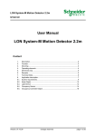
6.5
Occupancy Sensor (LONMARK® profile #1060)
Occupancy Sensor
#1060
nvoOSoccupancy[i]
SNVT_occupancy
UCPTbuttonRslOccCmd[i]
Output Network Variables
nvoOSoccupancy[i] – Occupancy Output
Type:
Valid Range:
Default Value:
Description:
SNVT_occupancy
OC_OCCUPIED, OC_UNOCCUPIED, OC_BYPASS, OC_STANDBY, OC_NUL
OC_NUL
Output to propagate the occupancy state.
Configuration Properties
UCPTbuttonRslOccCmd[i] – Occupancy command assignment to a close contact
Type:
Valid Range:
Default Value:
Description:
Version: 10.07.09
UNVT_occupancy
OC_OCCUPIED, OC_UNOCCUPIED, OC_BYPASS, OC_STANDBY,
OC_NO_MESSAGE, OC_NUL
OC_NO_MESSAGE
Used to assign an occupancy command to every button.
Subject to modifications
Page 21 of 21