1
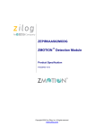
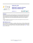
ZMOTION™ Detection and Control Development Kit User Manual 1 Introduction Zilog’s ZMOTION Development Kit provides a general-purpose platform for evaluating the capabilities and operation of the ZMOTION Detection and Control Family of microcontrollers featuring Zilog’s passive infrared (PIR) technology. The family includes a series of high-performance microcontrollers with integrated motion detection algorithms. A variety of included lenses and pyroelectric sensors demonstrate the flexibility of the integrated motion detection algorithms to provide the best possible performance for a range of lighting, detection and control applications. The Z8FS040 MCU, a prominent member of the ZMOTION Detection and Control Family, combines the programmability and rich peripheral set of Zilog’s Flash Z8 Encore! XP® Family of MCUs with built-in motion detection software algorithms to provide the functions necessary for PIR motion detection applications. These motion detection algorithms comprise Zilog’s PIR technology and run in the background while control and status of the motion detection engine is accessed through a software Application Programmer Interface (API). As a result, the designer can create his or her own application-specific software while taking advantage of Zilog’s ZMOTION Motion Detection Technology. Within this kit, API settings are provided to match the Engine operation to each of the lens and pyroelectric sensor combinations provided. For more details about the ZMOTION MCU, refer to the ZMOTION Product Specification (PS0284), available for download at www.zilog.com. UM023001-1110 Introduction ZMOTION™ Detection and Control Development Kit User Manual 2 Kit Contents The ZMOTION Detection and Control development kit contains the following hardware, software and documentation: Hardware • • • • • • • • • • ZMOTION Development Board USB Smart Cable Debugger 0.9" Focal Flat Lens Holder 0.77" Focal Circular Lens Holder Selection of lenses Selection of pyroelectric sensors Mica insulating washers DB9–DB9 serial cable Wall mount 5 V DC power supply An assortment of mounting hardware The contents of the kit are shown in Figure 1. UM023001-1110 Introduction ZMOTION™ Detection and Control Development Kit User Manual 3 Figure 1. ZMOTION Detection and Control Development Kit Contents UM023001-1110 Introduction ZMOTION™ Detection and Control Development Kit User Manual 4 Software (on CD-ROM) • • ZDS II – Z8 Encore! IDE with ANSI C-Compiler Sample Code: – ZMOTION Basic – ZMOTION Serial Documentation • ZMOTION Detection and Control Development Kit Quick Start Guide (QS0076) • ZMOTION Family Technical Documentation (on CD-ROM) – ZMOTION Detection Module Product Brief (PB0223) – Zilog’s ZMOTION Detection and Control Family Featuring PIR Technology Product Brief (PB0225) – ZMOTION Detection and Control Family Featuring PIR Technology Product Specification (PS0285) – ZMOTION Lens and Pyroelectric Sensor Product Specification (PS0286) – ZMOTION Detection and Control Development Kit User Manual (UM0230) – ZMOTION – A New PIR Motion Detection Architecture White Paper (WP0017) – ZMOTION Detection Lens and Pyro Sensor Configuration Guide (WP0018) – Board Schematic, assembly drawing and artwork Sample code files are included on the ZMOTION Sample Apps CD, and are located in the ZMOTION_Basic and ZMOTION_Serial folders. UM023001-1110 Introduction ZMOTION™ Detection and Control Development Kit User Manual 5 System Requirements An IBM PC (or compatible computer) with the following minimum configurations is required: • Microsoft Windows XP Professional SP1/Windows 2000 SP3/Windows NT 4.0 SP6/Windows 98 SE • • • • • • • Pentium II/233 MHz processor or higher up to Pentium IV, 2.8 GHz 96 MB RAM or more 25 MB hard disk space or more Super VGA video adapter CD-ROM drive One or more RS-232 communication ports USB 2.0 interface port Installation For details about installation and setup, refer to the Using the ZMOTION Detection and Control Development Kit Quick Start Guide (QS0076). Safeguards The following precaution must be observed when working with the devices described in this document. Caution: Always use a grounding strap to prevent damage resulting from electrostatic discharge (ESD). UM023001-1110 Introduction ZMOTION™ Detection and Control Development Kit User Manual 6 ZMOTION™ Detection and Control Development Board Zilog’s ZMOTION development board is a development and prototyping platform for the ZMOTION Detection and Control silicon and software as well as for lens/pyroelectric sensor/silicon and software bundled solutions. The board provides the user with a tool to evaluate the many features of ZMOTION PIR technology as well as the actual performance of each lens and pyro combination. UM023001-1110 ZMOTION™ Detection and Control ZMOTION™ Detection and Control Development Kit User Manual 7 Figure 2. ZMOTION Detection and Control Development Board Features The ZMOTION Detection and Control development board features the following elements: • • UM023001-1110 Z8FS040 ZMOTION Detection MCU (8-pin SOIC) RS-232 serial interface ZMOTION™ Detection and Control ZMOTION™ Detection and Control Development Kit User Manual 8 • • • • 5 V DC power connector Power-On and Detection LED On-chip debugger interface Board openings for an assortment of lens holders and clip-on lens attachments Note: The middle set of holes on the board is used to attach the 0.9″ and .77″ lens holders (see Figure 2). • • Prototyping area 2.7 V–3.6 V operating voltage with 5 V tolerant inputs MCU Features The Z8FS040 ZMOTION Detection MCU combines the programmability and rich peripheral set of Zilog’s Flash Z8 Encore! XP Family of MCUs with built-in motion detection software algorithms to provide the functions necessary for PIR motion detection applications. The Z8FS040 MCU includes the following features: • • High performance eZ8® MCU core • • • • • • Single-pin debug with unlimited breakpoints UM023001-1110 4 KB in-circuit programmable Flash memory available for application code Flexible clocking scheme Internal precision oscillator running at 5.53 MHz External oscillator operating up to 20 MHz Sigma Delta ADC Up to 6 single-ended channels or 3 differential channels available ZMOTION™ Detection and Control ZMOTION™ Detection and Control Development Kit User Manual 9 • On-chip analog comparator with independent programmable reference voltage • • Full-duplex UART with dedicated BRG • • • • Watchdog timer (WDT) with dedicated internal oscillator • Zilog PIR technology controlled and monitored via software API registers • Selection capability from an assortment of lenses and pyroelectric sensors to best fit your application • API settings provided for each lens and pyroelectric sensor combination • • • • Directly supports 1 or 2 pyroelectric sensors Two 16-bit timers with input capture, output compare and PWM capability (11 modes total) Up to 20 vectored interrupts 6 to 25 I/O pins depending upon package 2.7 V to 3.6 V operating voltage with extended operating temperature range –40° C to +105° C Sensitivity control, range control and directionality detection Extended detection modes for occupancy sensing Low power modes ZMOTION Detection and Control Development Kit Lens and Pyroelectric Sensors The ZMOTION Detection and Control Development Kit includes five different types of lenses and three different types of pyroelectric sensors to fill a wide variety of lighting control, occupancy sensing, HVAC, display, proximity and power management applications. These applications UM023001-1110 ZMOTION™ Detection and Control ZMOTION™ Detection and Control Development Kit User Manual 10 also demonstrate the flexibility, and superior performance of Zilog’s PIR motion detection technology. Please refer to the ZMOTION Lens and Pyroelectric Sensor Product Specification (PS0286) for part-specific details about the individual lenses and pyroelectric sensors. Refer to the ZMOTION™ Detection and Control Development Kit Quick Start Guide (QS0076) for specific installation instructions for the lenses and pyroelectric sensors. Lens Mounting Options The ZMOTION Development Board supports four lens-mounting options, as indicated in Table 1. Table 1. Four Supported Lens-Mounting Options Lens Mounting Lens Supported PIR Sensor Clip-On NCL-9(26) Circuit Board Clip-In CWM 0.5 GI V1 Circular Lens Holder 0.77 Focal CM 0.77 GI V3 CM 0.77 GI V5 Flat Lens Holder 0.9 Focal AA 0.9 GI T1 Pyroelectric Sensor Options Table 2 lists three types of pyroelectric sensors offered in the ZMOTION Detection and Control Development Kit. Table 2. Three Supported Pyroelectric Sensor Options Pyro Sensor Description Part Number Basic Dual Element RE200B-P Premium Dual Element SDA02-54-P Quad Element SBDI46-504AA UM023001-1110 ZMOTION™ Detection and Control ZMOTION™ Detection and Control Development Kit User Manual 11 ZMOTION Development Kit Application Software Included in the ZMOTION Application Software are two motion detection software projects: ZMOTION_Basic and ZMOTION_Serial. Each is decribed in this section. ZMOTION_Basic ZMOTION_Basic is an application program that demonstrates the basic functionality of motion detection for the board. It enables the user to select between lenses in the main.h file as well as make changes to the individual API lens configuration settings. Other changeable options in main.h are the LED duration time (0 sec to 30 minutes), hypersense on/ off and duration time. Detected movement is indicated via LED3. ZMOTION_Serial The ZMOTION_Serial project allows all the same options for making changes to key parameters within the application project. Detected movement is indicated via the following Hyperterminal menu options (see Figure 3). Menu. Select at any time to return to the main menu. Read RAM. Allows any 3-digit hexadecimal register address location in RAM to be read and displayed. Write RAM. Allows any 3-digit hexadecimal register address location in RAM to be written to. Real Time Log & Display. Selecting a 1 will turn on the motion detection log. The display is formatted by an M or E to indicate basic motion detection or extended detection, followed by the detection count and a relative time stamp. Selecting a 0 turns off the detection log. Reset Log/Display Counts. Clears out the display log and resets the count. Display Log. Displays the relative time stamp of each motion event, starting with the most recent event (highest time stamp). UM023001-1110 ZMOTION™ Detection and Control ZMOTION™ Detection and Control Development Kit User Manual 12 Prime. Selecting Prime will causes the Z8FS040 MCU to calculate and display sequential prime numbers. Motion detection continues to operate. Display API Registers. Displays the current values in each API register. For further information about API register settings, please refer to the ZMOTION Detection and Control Family Featuring Zilog’s PIR Technology Product Specification (PS0285). Figure 3. The ZMOTION_Serial project running in Hyperterminal UM023001-1110 ZMOTION™ Detection and Control ZMOTION™ Detection and Control Development Kit User Manual 13 Board Design Information Figure 4 displays the schematics for the ZMOTION Development Board. Figure 4. ZMOTION Development Board Schematic Diagram UM023001-1110 Board Design Information ZMOTION™ Detection and Control Development Kit User Manual 14 Figure 5 displays a mechanical drawing of the ZMOTION Development Board. Figure 5. ZMOTION Development Board Mechanical Diagram UM023001-1110 Board Design Information ZMOTION™ Intrusion Detection Development Kit User Manual 1 Introduction Zilog’s ZMOTION Intrusion Detection Development Kit provides a general-purpose platform for evaluating the capabilities and operation of the ZMOTION Intrusion Detection MCU, which features Zilog’s passive infrared (PIR) technology. The ZMOTION Family of Motion Detection products includes a series of high-performance microcontrollers with integrated motion detection algorithms. A variety of included lenses and pyroelectric sensors demonstrate the flexibility of the integrated motion detection algorithms to provide the best possible performance for a range of lighting, intrusion detection and security-related control applications. The Z8FS021 MCU, a prominent member of the ZMOTION Family, combines the programmability and rich peripheral set of Zilog’s Flash Z8 Encore! XP® Family of MCUs with built-in motion detection software algorithms to provide the functions necessary for PIR motion detection applications. These motion detection algorithms comprise Zilog’s PIR technology and run in the background while control and status of the motion detection engine is accessed through a software Application Programmer Interface (API). As a result, the designer can create his or her own application-specific software while taking advantage of Zilog’s ZMOTION Motion Detection Technology. Within this kit, API settings are provided to match the Engine operation to each of the lens and pyroelectric sensor combinations provided. For more details about the ZMOTION MCU, refer to the ZMOTION Detection Module Product Specification (PS0284), available for download at www.zilog.com. UM023301-0411 Introduction ZMOTION™ Intrusion Detection Development Kit User Manual 2 Kit Contents The ZMOTION Intrusion Detection Development Kit contains the following hardware, software and documentation: Hardware • • • • • • • • ZMOTION Development Board USB Smart Cable Debugger 1.2" Focal Flat Lens Holder Selection of lenses RE200B Pyroelectric Sensor mounted on the Development Board Mini-USB serial cable Wall mount mini-USB 5 V DC power supply1 An assortment of mounting hardware Software (on CD-ROM) • • ZDS II – Z8 Encore! IDE with ANSI C-Compiler Sample Code: ZMOTION_Intrusion_Demo Documentation • ZMOTION Intrusion Detection Development Kit Quick Start Guide (QS0078) • ZMOTION Family Technical Documentation (on CD-ROM) – ZMOTION Intrusion Detection Product Specification (PS0288) – ZMOTION Intrusion Detection Product Brief (PB0230) 1. Zilog recommends using only the power supply provided in the ZMOTION Intrusion Detection Development Kit. UM023301-0411 Introduction ZMOTION™ Intrusion Detection Development Kit User Manual 3 – – – – – – – – – – ZMOTION Detection and Control Product Specification (PS0285) ZMOTION Detection and Control Product Brief (PB0225) ZMOTION Detection Module Product Specification (PS0284) ZMOTION Detection Module Product Brief (PB0223) ZMOTION Lens and Pyroelectric Sensor Product Specification (PS0286) ZMOTION Intrusion Detection Development Kit User Manual (UM0233) ZMOTION Intrusion Detection Development Kit Quick Start Guide (QS0078) ZMOTION – A New PIR Motion Detection Architecture White Paper (WP0017) ZMOTION Detection Lens and Pyro Sensor Configuration Guide (WP0018) Board Schematic, assembly drawing and artwork The contents of the kit are shown in Figure 1. UM023301-0411 Introduction ZMOTION™ Intrusion Detection Development Kit User Manual 4 ZMOTION Intrusion Detection Development Board Three 1.2" Intrusion Detection lenses Power supply with International plugs ZDS II Smart Cable 1.2" Lens Holder Mini-USB to USB Cable Figure 1. ZMOTION Intrusion Detection Development Kit Contents Sample code files are included on the ZMOTION Sample Applications CD, and are located in the ZMOTION_Intrusion_Demo folders. UM023301-0411 Introduction ZMOTION™ Intrusion Detection Development Kit User Manual 5 System Requirements An IBM PC (or compatible computer) with the following minimum configurations is required: • Microsoft Windows 7, Windows XP Professional SP1, Windows 2000 SP3, Windows NT 4.0 SP6 • • • • • • Pentium II/233 MHz processor or higher up to Pentium IV, 2.8 GHz 96 MB RAM or more 25 MB hard disk space or more Super VGA video adapter CD-ROM drive USB 2.0 interface port Installation For details about installation and setup, refer to the Using the ZMOTION Intrusion Detection Development Kit Quick Start Guide (QS0078). Safeguards The following precaution must be observed when working with the devices described in this document. Caution: Always use a grounding strap to prevent damage resulting from electrostatic discharge (ESD). UM023301-0411 Introduction ZMOTION™ Intrusion Detection Development Kit User Manual 6 ZMOTION Intrusion Detection Development Board Zilog’s ZMOTION Intrusion Detection Development Board is a development and prototyping platform for the ZMOTION Intrusion Detection silicon and software as well as for lens/pyroelectric sensor/silicon and software bundled solutions. The Board provides the user with a tool to evaluate the many features of ZMOTION PIR technology, as well as the actual performance of each lens and pyro combination. Note: Attach the Intrusion lens holder to the Board using the primary placement set of holes, which are indicated in Figure 2. Primary Placement Holes Figure 2. ZMOTION Intrusion Detection Development Board UM023301-0411 ZMOTION Intrusion Detection Development Board ZMOTION™ Intrusion Detection Development Kit User Manual 7 Features The ZMOTION Intrusion Detection Development Board features the following elements: • • • • • Z8FS021 ZMOTION Detection MCU (20-pin SSOP) Mini-USB power connector and serial interface Power-On and Detection LED On-chip debugger interface Board openings for an assortment of lens holders and clip-on lens attachments Note: The upper set of holes on the board is used to attach the 1.2" lens holders (see Figure 2). • • Prototyping area 2.7 V–3.6 V operating voltage with 5 V tolerant inputs MCU Features The Z8FS021 ZMOTION Intrusion Detection MCU combines the programmability and rich peripheral set of Zilog’s Flash Z8 Encore! XP Family of MCUs with built-in motion detection software algorithms to provide the functions necessary for PIR motion detection applications. The Z8FS021 MCU includes the following features: • • High performance eZ8® MCU core • Single-pin debug with unlimited breakpoints UM023301-0411 2 KB in-circuit programmable Flash memory available for application code ZMOTION Intrusion Detection Development Board ZMOTION™ Intrusion Detection Development Kit User Manual 8 • • • • • • Flexible clocking scheme • • Full-duplex UART with dedicated BRG • • • • Watchdog timer (WDT) with dedicated internal oscillator • Zilog PIR technology controlled and monitored via software API registers • Selection capability from an assortment of lenses and pyroelectric sensors to best fit your application • API settings provided for each lens and pyroelectric sensor combination • • • • • Directly supports 1 or 2 pyroelectric sensors UM023301-0411 Internal precision oscillator running at 5.53 MHz External oscillator operating up to 20 MHz Sigma Delta ADC Up to 6 single-ended channels or 3 differential channels available On-chip analog comparator with independent programmable reference voltage Two 16-bit timers with input capture, output compare and PWM capability (11 modes total) Up to 20 vectored interrupts 6 to 25 I/O pins depending upon package 2.7 V to 3.6 V operating voltage with extended operating temperature range –40° C to +105° C Sensitivity control, range control and directionality detection Extended detection modes for occupancy sensing Low power modes White light detection and pet immunity ZMOTION Intrusion Detection Development Board ZMOTION™ Intrusion Detection Development Kit User Manual 9 ZMOTION Intrusion Detection Development Kit Lens and Pyroelectric Sensor The ZMOTION Intrusion Detection Development Kit includes three different types of lenses to fill a wide variety of intrusion detection and security applications. These applications also demonstrate the flexibility, and superior performance of Zilog’s PIR motion detection technology. Please refer to the ZMOTION Lens and Pyroelectric Sensor Product Specification (PS0286) for part-specific details about the individual lenses and pyroelectric sensors. Refer to the ZMOTION Intrusion Detection Development Kit Quick Start Guide (QS0078) for specific installation instructions for the lenses. Lens Mounting Options The ZMOTION Development Board supports a lens holder option for each of the 1.2" focal length intrusion lenses, as indicated in Table 1. For lens installation instructions, please refer to the ZMOTION Intrusion Detection Development Kit Quick Start Guide (QS0078). Table 1. Lens Mounting Options Lens Mounting Supported Lenses Flat Lens Holder 1.2 Focal WA 1.2 GI 12 V4 VB 1.2 GI V1 LR 1.2 GI 12 V3 Pyroelectric Sensor Option The ZMOTION Intrusion Detection Development Kit includes one type of pyroelectric sensor, the Basic Dual Element sensor, part number RE200B-P, which is mounted directly on the Board. UM023301-0411 ZMOTION Intrusion Detection Development Board ZMOTION™ Intrusion Detection Development Kit User Manual 10 ZMOTION Development Kit Application Software The ZMOTION application software includes the ZMOTION_Intrusion_Demo motion detection project, which is described in this section. ZMOTION_Intrusion_Demo The ZMOTION_Intrusion_Demo project demonstrates the basic motion detection functionality of the ZMOTION Development Board. The MCU included with the Board is programmed with this project. Each lens type is supported by an associated lens configuration header file which displays a name format of API_INIT_xx.h. Header files for all supported lens types are included in the include project folder of the ZMOTION_Intrusion_Demo project. The main.c source file contains the include directive to add the header file to the project. Changes to these header files should not be required, but any modifications you make should be made to a copy of the original header file; do not modify the original versions. As new lens types are added to the ZMOTION family, an associated lens configuration file is made available on the Zilog website. Table 2 lists additional project features that can be modified or enabled in main.c and main.h. Table 2. Additional Project Features Feature LED on time duration File main.c Define/Variable cMDDelayTime White Light Immunity On/Off White Light Threshold White Light Anti-Jam On/Off Detailed Status Reporting On/Off Lens Support main.h WHITE_LIGHT Default Values DELAY_1SEC (1 second) 0 (Off) main.h main.h WHITE_LIGHT_THRESH_DEF WHITE_LIGHT_ANTI_JAM_DEF 0x1F (Max) 0 (Off) main.h VERBOSE 0 (Off) main.c #include "API_INIT_xx.h" API_INIT_09.h UM023301-0411 ZMOTION Intrusion Detection Development Board ZMOTION™ Intrusion Detection Development Kit User Manual 11 When motion is detected, the LED is turned ON for 1 second (cMDDelayTime). A serial terminal program such as HyperTerminal can be used to view the detection messages from the ZMOTION Development Board (see Figure 3). In the figure, r045 indicates the version of the application; the S following it is displayed when the pyroelectric sensor has become stable and the system is ready to detect motion. When motion is detected, an M or E is displayed to indicate the type of detection (normal Motion or Extended motion), along with the count and a time stamp (in seconds) after power-up. Figure 3. The ZMOTION_Intrusion_Demo project running in HyperTerminal UM023301-0411 ZMOTION Intrusion Detection Development Board ZMOTION™ Intrusion Detection Development Kit User Manual 12 Installing ZDS II and the USB Smart Cable Observe the following the steps to install Zilog Developer Studio (ZDS II) and its associated documentation. 1. Insert the ZDS II CD into the CD-ROM drive. The DemoShield installer launches automatically. If DemoShield does not launch automatically, open Windows Explorer, browse to your CD-ROM drive and double-click launch.exe to launch DemoShield. 2. From the product installer list, you can choose to install ZDS II alone, or both ZDS II and its associated documentation. You can also copy the documentation directly from your CD-ROM drive to your hard disk using Windows Explorer, or read the documentation directly from the CD-ROM itself. For customer service and technical support, Zilog recommends that you create an account at support.zilog.com. Installing the USB Smart Cable This section describes how to install the USB Smart Cable and associated driver software for your particular operating system. Windows 7 32/64 Observe the following steps to install the USB Smart Cable for Windows Vista 32-bit systems. 1. Connect the USB Smart Cable to the Host PC. A window message stating Driver Software Installation appears. 2. Windows automatically searches the driver; this process can sometimes take a few minutes to complete. In this case, wait for the search to complete, since there is no option to terminate this process immediately. If the driver was previously installed, Windows automatically installs the USB Smart Cable driver. If this is the case, proceed to Step 9. If Win- UM023301-0411 ZMOTION Intrusion Detection Development Board ZMOTION™ Intrusion Detection Development Kit User Manual 13 dows cannot find the driver, close the Search dialog and continue to Step 3. 3. In the Windows Start menu’s Search programs and files field, enter Device Manager and click the Enter key. A Device Manager link will appear in the Start menu’s resulting Program list; click to launch it. 4. In the Device Manager, under Other devices, right-click USB Smart Cable. 5. Select Update Driver Software. 6. In the Update Driver Software - USB Smart Cable dialog, select the Browse my computer for driver Software option. 7. Browse to one of the following driver directories: For 32-bit versions: <ZDS II Installation Directory>\device drivers\USB\x32 <ZDS II Installation CD>\device drivers\USB\x32 For 64-bit versions: <ZDS II Installation Directory>\device drivers\USB\x64 <ZDS II Installation CD>\device drivers\USB\x64 8. Click Next to install the driver. On 32-bit systems, a Windows Security dialog will appear; select Install this driver software anyway. 9. After the Wizard finishes the installation, click the Close button. Windows Vista, 32-bit OS Observe the following steps to install the USB Smart Cable for Windows Vista 32-bit systems. UM023301-0411 ZMOTION Intrusion Detection Development Board ZMOTION™ Intrusion Detection Development Kit User Manual 14 1. Connect the USB Smart Cable to the host PC. The Found New Hardware dialog box is displayed. 2. Select Locate and install the driver software (recommended). The Driver Software Installation window is displayed, followed by the Found New Hardware-USB Smart Cable dialog box. 3. When prompted, select I don't have the disc. Show me other options. 4. When prompted, select Browse my computer for driver software (advanced). 5. Browse to the following driver directory: <ZDS II Installation Directory>\device drivers\USB 6. The Windows Security dialog box is displayed; select Install this driver software anyway. 7. Upon successful installation, click Close. Windows XP Observe the following steps to install the USB Smart Cable for Windows XP systems. 1. Connect the Zilog USB device to the host PC. The Found New Hardware wizard should activate automatically after connecting the Zilog USB device for the first time. If prompted to connect to Windows Update, select No, not at this time. 2. Select [Install from a list or specific location (Advanced)]; then click Next. Note: If the Windows Logo testing dialog appears, select Continue Anyway. UM023301-0411 ZMOTION Intrusion Detection Development Board ZMOTION™ Intrusion Detection Development Kit User Manual 15 3. Select Search for the best driver in these locations and Include this location in search. 4. Browse to the following driver directory, then click Next. <ZDS installation>\device drivers\USB\ 5. After you find the appropriate driver, click Next. 6. Click Finish to complete the installation. Windows 2000 Observe the following steps to install the USB Smart Cable for Windows 2000 systems. 1. Connect the Zilog USB device to the host PC. The Found New Hardware wizard should activate automatically after connecting the Zilog USB device for the first time. 2. After the Found New Hardware wizard has been activated, click Next. 3. Select Search for a suitable driver for my device (Recommended), then click Next. 4. Select Specify a location and click Next. 5. Browse to the following driver directory, then click OK. <ZDS installation>\device drivers\USB\ 6. After you find the appropriate driver, click Next. 7. Click Finish to complete the installation. Connecting the USB Smart Cable Observe the following steps to connect the USB Smart Cable to the ZMOTION Development Board. UM023301-0411 ZMOTION Intrusion Detection Development Board ZMOTION™ Intrusion Detection Development Kit User Manual 16 Caution: The power to the development board must be disconnected or turned OFF before connecting or disconnecting the USB Smart Cable. 1. Attach one end of the six-conductor ribbon cable (included) to the USB Smart Cable six-pin DBG connector, as shown in Figure 4. Figure 4. Connecting the Six-Conductor Ribbon Cable to the USB Smart Cable 2. Attach the free end of the ribbon cable to the DBG connector (ZDI Interface) on the development board. Ensure that pin 1 on the ribbon cable (indicated by the dark stripe) is aligned with pin 1 on the target connector (indicated by a 1 on P2 of the board). UM023301-0411 ZMOTION Intrusion Detection Development Board ZMOTION™ Intrusion Detection Development Kit User Manual 17 Installing the FTDI USB to Serial Driver Observe the following steps to install the FTDI USB to Serial Driver. 1. Make sure that the USB cable is not plugged into the ZMOTION Development Board. 2. On the CDROM, double-click the CDM20802_Setup.exe file to start the driver installation. The installation process will begin, and will appear similar to the following code statements: 32-bit OS detected <installation path>\dpinstx86.exe Installation driver FTDI CDM driver installation process completed. 3. When the installation is complete, plug the USB cable into the ZMOTION Development Board. 4. If driver installation was successful, USB Serial Port (COMx) should appear in the list displayed in the Device Manager’s Ports (COM & LPT) interface. To open the Device Manager on Windows 7 systems, launch the Start menu, enter Device Manager in the Search program and files field, and press the Enter key. To open the Device Manager on earlier Windows systems, navigate to the following filepath: Start → Control Panel → System → Hardware → Device Manager → Ports (COM &LPT). Downloading and Running the Sample Project Sample projects are included on the Application CD. Copy these projects to a convenient folder on your PC. Once copied, ensure the folders are not UM023301-0411 ZMOTION Intrusion Detection Development Board ZMOTION™ Intrusion Detection Development Kit User Manual 18 set to Read Only by right-clicking the folder and selecting properties. Deselect the Read Only attribute and click OK. Make sure you apply changes to this and the other subfolders when prompted. In this example, we reference the ZMOTION_Intrusion_Demo project; however, the steps that follow will apply to any additional project. Note: At this point you should have loaded ZDS II and the Smart Cable USB driver on to your computer. If you haven’t yet done so, revisit the beginning of this Installing ZDS II and the USB Smart Cable section before proceeding. 1. Open ZDS II and select File → Open Project, then navigate to the project folder labeled ZMOTION_Intrusion_Demo. 2. Open the ZMOTION_Intrusion_Demo.zdsproj project. When you first receive your kit, this project is already loaded into the ZMOTION MCU. Right-click within the open grey area below the menu icons and select Workbook Mode to turn on the tabs at the bottom of the editor and therefore make it easier to switch between files. 3. Click the Rebuild All icon to build the project. The build output should not indicate any errors. If you receive errors, try reloading the projects from the original Application CD and ensure that the folders are not set to Read Only. See Figure 5 for an example; Figure 6 indicates the location of the Rebuild All icon in the ZDS II menu bar. UM023301-0411 ZMOTION Intrusion Detection Development Board ZMOTION™ Intrusion Detection Development Kit User Manual 19 Figure 5. Building the ZMOTION_Intrusion_Demo project in ZDS II The Rebuild All icon Figure 6. The Location of the Rebuild All Icon UM023301-0411 ZMOTION Intrusion Detection Development Board ZMOTION™ Intrusion Detection Development Kit User Manual 20 4. Make sure that the ZMOTION Development Board is powered OFF, then connect the USB Smart Cable (Debugger) to P2, as described above. 5. Apply power to the Development Board by plugging in the USB cable and setting SW1 to the ON position. Next, click the Reset icon in ZDS II. Figure 7 indicates the location of both the Reset and Go icons in the ZDS II menu bar. The Reset icon The Go icon Figure 7. The Location of the Rest and Go Icons 6. An information notice may appear, indicating that the silicon is not the latest version. This occurrence is normal and is not an issue. Click OK to continue. You should see a message in the Debug Output Window indicating that the load was successful, as shown in Figure 8. UM023301-0411 ZMOTION Intrusion Detection Development Board ZMOTION™ Intrusion Detection Development Kit User Manual 21 Figure 8. ZDS II’s Debug Output Window for the ZMOTION_Basic project 7. Click the Go icon to start the application running. The Red LED (LED2) will be ON initially until the pyroelectric sensor stabilizes – a period that can take up to 30 seconds. After it has stabilized, (LED2) turns OFF, to turn ON only when motion is detected. 8. To test this procedure, wave your hand over the lens and notice (LED2) turning ON for approximately 1 second. UM023301-0411 ZMOTION Intrusion Detection Development Board ZMOTION™ Intrusion Detection Development Kit User Manual 22 Making Changes to the ZMOTION_Intrusion_Demo Project To change the duration of the LED on time, observe the following procedure. 1. Change the following line in the main.c file: unsigned int cMDDelayTime = DELAY_1SEC; // LED ON time 2. Change the line as follows to select a five-second LED on time: unsigned int cMDDelayTime = DELAY_5SEC; // LED ON time Note: LED on time definitions are provided in the main.h file for values from 200 ms to 30 minutes. 3. Click the Rebuild icon to build the project. The build output should not indicate any errors. Click the Go icon to download the modified project and start the application running. Generate motion and notice that the LED now stays on for 5 seconds. 4. To change the lens used by the project, edit the include line at the top of the main.c file to include the appropriate API_INIT file. The project initially uses API_INIT_09.h to support the WA 1.2 GI 12 V4 (board clip-in) lens (see the code sample below). To use a different lens, edit out the comment characters (//) in the main.c file that correspond to the new lens, and comment out the lens that is no longer in use. replace with: // This file must match the lens and PIR sensor used in the application //#include "API_INIT_00.h" // Generic settings: non-lens-specific //#include "API_INIT_01.h" // API configuration file for AA 0.9 GI V1 Lens //#include "API_INIT_02.h" // API configuration file for CM 0.77 GI V3 Lens UM023301-0411 ZMOTION Intrusion Detection Development Board ZMOTION™ Intrusion Detection Development Kit User Manual 23 //#include "API_INIT_03.h" //#include "API_INIT_04.h" //#include "API_INIT_05.h" //#include "API_INIT_06.h" //#include "API_INIT_07.h" //#include "API_INIT_08.h" #include "API_INIT_09.h" //#include "API_INIT_10.h" //#include "API_INIT_11.h" // // // // // // // // // API API API API API API API API API configuration configuration configuration configuration configuration configuration configuration configuration configuration file for CM 0.77 GI V5 Lens file for CWM 0.5 GI V1 Lens file for NCL-9(26) Lens file for NCL-10IL Lens file for NCL-3B Lens file for NCL-11 Lens file for WA1.2 GI 12 V4 Lens file for LR1.2 GI 12 V3 Lens file for VB1.2 GI V1 Lens The API_INIT file must match the lens and pyroelectric sensor being used on the Development Board. Use the Lens Selection Guide in the ZMOTION Lens and Pyroelectric Sensor Product Specification (PS0286) to determine which API_INT file is required for each lens and Pyroelectric Sensor combination. UM023301-0411 ZMOTION Intrusion Detection Development Board ZMOTION™ Intrusion Detection Development Kit User Manual 24 Board Design Information Figure 9 displays the schematics for the ZMOTION Development Board. VCC_5v U1 1 2 L1 FERRITE BEAD C1 C2 4.7uF 0.1uF R3 20K 6 R4 4.75K Vin Vout GND GND EN 3 VCC_3v3 5 4 NC NCP582LXV33T2G C3 C4 4.7uF 0.1uF SH1 SH2 SH3 SH4 VBUS DM DP ID GND 1 2 3 4 5 USB PWR C5 1 2 3 P1 6 7 8 9 WALL PWR HDR/PIN 1x3 J5 0.01uF USB-OTG, mini-AB PWR SRC U2 4 20 16 15 VCCIO TXD VCC RXD RTS USBDM CTS USBDP DTR 8 R5 19 100K 24 27 28 17 NC1 DSR RESET DCD NC RI OSCI CBUS0 OSCO CBUS1 CBUS2 3v3 OUT GND3 GND2 GND1 TEST 26 21 18 7 25 0.1uF AGND CBUS3 C6 CBUS4 1 5 RXD VCC_3v3_T TXD 3 SW1 11 2 1 2 PWR ON 3 9 EG1218 10 6 23 22 13 14 U3 12 1 C7 C8 0.1uF 4.7uF 2 FT232RL 3 OUT IN 5 R6 20K GND OC EN 4 1 TPS2051B RED D3 2 VCC_3v3 R7 100 ohm Figure 9. ZMOTION Development Board Schematic Diagram, #1 of 2 UM023301-0411 Board Design Information ZMOTION™ Intrusion Detection Development Kit User Manual 25 J6 3.3V 1 VCC_3v3_T HDR/PIN 1x1 J1 R8 ANA2 LED1 1 2 1 VCC_3v3_T HDR/PIN 1x1 BLUE 1K U8 3.3V PB1/ANA1 J2 GND MOTION 1 HDR/PIN 1x1 1 2 470 GND PA0 PA1 LED3 R9 J3 GND C9 1uF 1 PA2 PA3 PA4/RXD0 PB1/ANA1 RXD 1 2 3 4 5 6 7 8 9 10 PB1/ANA1 PB0/ANA0 ANA2 PC3/COUT/ ANA3 PC2/ANA6/LED/VREF VDD PC1/ANA5/CINN PA0/T0IN/T0OUT/XIN PC0/ANA4/CINP PA1/T0OUT/XOUT DBG VSS RESET/PD0 PA2/DE0 PA7/T1OUT PA3/CTS0 PA6/T1IN/T1OUT PA4/RXD0 PA5/TXD0 RED 20 19 18 17 16 15 14 13 12 11 Z8FS040xHH20EG PB0 PC3 VCC_3v3_T PC1 PC0 R11 100K PD0 PA7 PA6 PA5/TXD0 TXD R10 HDR/PIN 1x1 0 ohm J9 1 2 3 4 5 6 7 8 9 10 11 12 13 PB1/ANA1 PA0 PA1 PA2 PA3 PA6 PA7 PD0 PC0 PC1 PC3 PB0 VCC_3v3_T RST J8 VCC_3v3_T R12 10K 1 2 R13 10K VCC_3v3_T P2 HDR/PIN 1x2 2 4 6 DBG IN FOR DBG HDR/PIN 1x13 1 3 5 1 HDR/PIN 2x3 PB1/ANA1 PB1 PA0 PA1 PA2 PA3 ANA2 PA6 PA7 PD0 PC0 PC1 PC3 PB0 2 1 2 3 4 5 6 7 8 R15 47K LED2 16 15 14 13 12 11 10 9 16 15 14 13 12 11 10 9 spare GND S RED 1 10 11 12 13 14 15 16 17 18 10 11 12 13 14 15 16 17 18 proto9x20 U6 1 2 3 4 5 6 7 8 C11 1 uF 3 2 PROTOTYPE AREA (.1X.1 GRID) DO NOT POPULATE HEADERS VCC_3v3_T U5 PyroSensor D R14 470 STATUS & WHITE LIGHT DETECTION U7 1 2 3 4 5 6 7 8 1 2 3 4 5 6 7 8 16 15 14 13 12 11 10 9 16 15 14 13 12 11 10 9 1 2 3 4 5 6 7 8 9 1 2 3 4 5 6 7 8 9 spare Zilog Confidential All Rights Reserved Zilog 6800 Santa Teresa Blvd San Jose, CA 95119 408-513-1500 Website: www.zilog.com Title ZMOTION Bundled Solutions 20-Pin Series Development Kit Page UNCONTROLLED WHEN PRINTED UNLESS STAMPED 'CONTROLLED COPY' IN RED BY DOCUMENT CONTROL Size B Date: Schematic Document Number Thursday March 10 2011 96C1309-001G Sheet 2 of 2 Figure 10. ZMOTION Development Board Schematic Diagram, #2 of 2 UM023301-0411 Board Design Information ZMOTION™ Intrusion Detection Development Kit User Manual 26 Figures 11 and 12 display top- and bottom-view mechanical drawings, respectively, of the ZMOTION Development Board. Figure 11. ZMOTION Development Board Mechanical Diagram, Top View UM023301-0411 Board Design Information ZMOTION™ Intrusion Detection Development Kit User Manual 27 Figure 12. ZMOTION Development Board Mechanical Diagram, Bottom View UM023301-0411 Board Design Information ZMOTION™ Intrusion Detection Development Kit User Manual 28 Customer Support To share comments, get your technical questions answered, or report issues you may be experiencing with our products, please visit Zilog’s Technical Support page at http://support.zilog.com. To learn more about this product, find additional documentation, or to discover other facets about Zilog product offerings, please visit the Zilog Knowledge Base at http://zilog.com/kb or consider participating in the Zilog Forum at http://zilog.com/forum. This publication is subject to replacement by a later edition. To determine whether a later edition exists, please visit the Zilog website at http://www.zilog.com. UM023301-0411 Customer Support