1
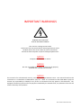
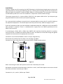
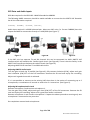
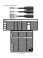
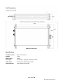
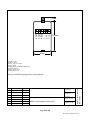
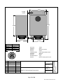
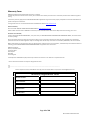
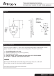
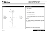
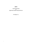
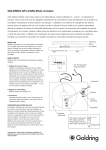
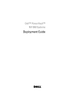
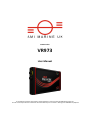
VHF Recorder VR973 User Manual © This Manual and the information contained therein is the property of AMI Marine (UK) Ltd. It must not be reproduced or otherwise disclosed without prior consent in writing from AMI Marine (UK) Ltd This Page Intentionally Blank Page 2 of 20 Manual VR973 Iss01 Rev03.docx Document Issue Iss01 Rev00 Iss01 Rev01 Iss01 Rev02 Iss01 Rev03 Date 30.06.13 25.09.13 27.01.14 18.03.14 Modification Number (where applicable) Brief Record of Change and Reason for Change Original Issue Addition of Microphone option Update of figure 08 (P.13) Change of address NOTE: All alterations must be verified and authorised by the Quality Manager. Page 3 of 20 Manual VR973 Iss01 Rev03.docx This Page Intentionally Blank Page 4 of 20 Manual VR973 Iss01 Rev03.docx IMPORTANT WARNINGS DANGER: HIGH VOLTAGE! RISK OF ELECTRICAL SHOCK! This unit has a voltage source inside. Disconnect from the power before removing protective covers. DO NOT remove the covers while the unit is switched on. 24 Volt DC electrical power on (when fitted) peripheral units. NOTICE Compass safe distance is 2 metres. NOTICE No user serviceable parts inside, servicing only by properly qualified and certified technical staff. NOTICE This manual is for informational use only, and may be changed without notice. This manual should not be construed as a commitment of AMI Marine (UK) Ltd. Under no circumstances does AMI Marine (UK) Ltd assume any responsibility or liability for any errors or inaccuracies that may appear in this document. The equipment should only be used for the purposes intended by the manufacturer; any deviation from this will void the warranty of the product. Page 5 of 20 Manual VR973 Iss01 Rev03.docx This Page Intentionally Blank Page 6 of 20 Manual VR973 Iss01 Rev03.docx Product Description OPERATORS MANUAL CONTENTS Introduction ........................................................................................................................................... 9 Visual Overview...................................................................................................................................... 9 Operating Instructions ......................................................................................................................... 10 Recorded File Playback ........................................................................................................................ 11 Installation ........................................................................................................................................... 12 GPS Data and Audio Inputs .................................................................................................................. 13 Terminations and Connections ............................................................................................................ 14 Specifications ....................................................................................................................................... 15 FAQ ....................................................................................................................................................... 18 Warranty Form..................................................................................................................................... 19 AMI MARINE (UK) LTD Unit 9, Crosshouse Centre Crosshouse Road Southampton SO14 5GZ United Kingdom Tel No Fax No E-mail Web +44 (0) 23 8048 0450 +44 (0) 23 8048 0451 [email protected] www.amimarine.net Page 7 of 20 Manual VR973 Iss01 Rev03.docx This Page Intentionally Blank Page 8 of 20 Manual VR973 Iss01 Rev03.docx Introduction The VR973 VHF Recorder is designed to record the VHF audio, along with date, time and position, on-board workboats, fishing boats and other vessels that do not require a VDR/SVDR system. Clear communication is a vital part of marine operations and the VHF recorder is an effective tool to assist owners/operators of smaller vessels to create an accurate history of events, whether it is for litigation or training and education purposes. Date, time and position are obtained from the vessels own GPS system and is a simple two wire connection with no setup required. The VHF audio is connected directly to the VR973 if available, as is the case with many modern VHF radios. For any VHF radios that do not have a dedicated output for a VDR/SVDR, which may be the case with older VHFs and those designed specifically for small boats, the KW973 VHF Interface may be used to combine the separate transmit and receive audio signals to be fed to the VR973 VHF Recorder. The audio and GPS data are saved onto an SD card which can be accessed by any computer with a suitable SD card reader and speakers which supports the playing of AVI format files. The saved files are in one minute increments and can be played back using an appropriate media player. During audio playback the GPS information is displayed on screen along with the system’s serial number. A Video Out port is also included for real-time monitoring (sync on green) Visual Overview PL1 Power Cable Socket Power ON LED Recording LED PL2 Signal Cable Socket LDR Video Out SD Card Slot Power On/Off Figure 1. Page 9 of 20 Manual VR973 Iss01 Rev03.docx Operating Instructions To access the SD card slot and the Power On/Off switch, unlock the side panel using the key supplied and lift open the cover. Ensure the SD card has the “Lock” tab disabled as shown in Figure 2. This is to ensure the saving of the files to the card. Lock Tab Figure 2. Figure 3. Insert the SD card into the SD Card slot with the label facing away from you as shown in Figure 3. Set the On/Off switch to ON (see Figure 1.) the Red POWER LED will immediately illuminate quickly followed by the Green RECORDING LED. This indicates that the recording process has started. After one minute the first file will be saved onto the SD card and the second file will begin to record. This process will continue until the SD card reaches capacity. At this time the oldest file will be overwritten by the newest to ensure continuous recording. It will take approximately 2 to 3 minutes after the initial switching on for the system date and time to be synchronised with the GPS date and time. Should the GPS fail the CPU clock will continue to upkeep the date and time. Switching the system OFF will begin the shutdown process. Once the On/Off switch is set to OFF the file currently being recorded will complete its recording process and save the final file before shutting down. Once both the Red and Green LEDs are off it is then safe to remove the SD card. Caution! Do not remove the SD card until the Red and Green LEDs are both OFF or corruption to the current file may occur, or worse the possibility may occur that the complete SD Card will become corrupt and unreadable resulting in the necessary formatting and loss of all recorded data. Page 10 of 20 Manual VR973 Iss01 Rev03.docx Recorded File Playback To play back the recorded files slot the SD card into your computer’s SD card reader, if you do not have this facility you will require the use of a USB multi card reader adaptor. Open the file explorer and navigate to the SD Card and its folders and files. Once there you will find many folders, one created for each day and is named YYYYMMDD e.g. [20130710] 10th of July 2013. Inside the folders the recorded AVI files can be found, one AVI file for every minute and named HHMM###P.AVI e.g. [1502461P.AVI] indicating that the file started recording at 15:02. The ‘Date modified’ column in the file explorer indicates when the file finished recording. Figure 4. Locate the date of the folder you are interested in and open. You can then further refine your search by locating the time stamp of the file you wish to replay. Once located double click on the relevant file. On playback you will hear the audio from the VHF and on the screen view the vessels details, position, course, speed and the date and time. Figure 5. Page 11 of 20 Manual VR973 Iss01 Rev03.docx Installation Locate a suitable area for mounting the VR973 keeping in mind to keep enough space to access the right hand side for inserting and operating the key, inserting and removing the SD Card and also the fitting of cables PL1 and PL2. A space of 400 x 200mm is recommended. The orientation of the legs can be fixed as preferred. A Torx 10 screwdriver is required to remove and fix the legs. The system comes with 2 x 1 metre cables. Cable PL1 is the power cable with a 2 pin bayonet type plug and Cable PL2 comes with a 6 pin bayonet type plug. For a neat and tidy installation a junction box is recommended to connect the PL1 and PL2 cables to the peripheral equipment. This would require an 8 way terminal strip. AMI can supply as extra. If the VHF equipment does not have available a dedicated output for a VDR then use of the KW973 VHF interface is required. There is a dedicated 12v supply from the VR973 specifically for the KW973 VHF interface. If connecting to a Sailor VHF or OEM, then KW973 VHF interface should be placed in a position close to the VHF to enable the handset cable to reach. All cables are to be fed through the glands supplied and connected to the appropriate connectors. Connection to the Sailor RT2048 or similar is simply ‘Plug and Play’. Disconnect the handset from the Sailor Unit and plug into DSK9. Connect the ribbon cable from PL1 (SK1) to the Sailor RT2048 Handset socket. 50mm RX/CH1 GND TX/CH2 GND 100mm +V GND TEST OUT TEST IN AU+ AU- 1 2 3 4 5 6 Figure 6. When connecting to other VHF systems connect the TX and RX pairs to SK2. RX Speaker connection should be made to SK2 Pins 1 and 2, and TX Microphone connection should be made to SK2 Pins 3 and 4 as per Table 2. Connect AU+, AU-, and +V, GND as per Table 3. Page 12 of 20 Manual VR973 Iss01 Rev03.docx GPS Data and Audio Inputs GPS data required is the IEC61162-1 NMEA Standard at 4800Bd. The following NMEA sentences should be made available to ensure that the VR973 VHF Recorder has all the information required $GPGGA, $GPRMC, $GPZDA, $GPVTG, Audio input required is a 600Ω balanced pair. Most new VHF units (i.e. Furuno FM8800) have this output available for connection directly to a VDR/SVDR (see Figure 7). Figure 7. Figure 8. Figure 9 If the VHF unit has separate TX and RX channels this can be connected via AMI’s KW973 VHF interface which will combine the 2 audio signals into 1 (see Figure 8). There is also the facility in the KW973 VHF interface to balance the volume levels (see Figure 6). Adjusting KW973 VHF Interface TX and RX Audio Levels Adjusting KW973 Audio Levels Turn the gain on both the TX and RX (see Figure 6). fully counter clockwise (CCW), adjust each gain level clockwise (CW) 25% of the full movement. Remove the SD card and replay the recording. Adjust until a good clear audio is achieved. If it is not possible to connect to the existing VHF then there is the option of connecting up to 2 microphones, a combination of internal or external or 2 x internal etc. (see Figure 9). Adjusting Microphone Audio Level Remove microphone 2 and connect microphone 1. Turn the gain fully (CCW), adjust each gain level (CW) 25% of the full movement. Remove the SD card and replay the recording. Adjust until a good clear audio is achieved. Remove microphone 1 and connect microphone 2. Repeat the above procedure ensuring only one microphone is connected at any one time. On completion connect both microphones. Page 13 of 20 Manual VR973 Iss01 Rev03.docx Terminations and Connections VR973 – Terminal and Junction Box Connections Equipment Termination DC GPS VHF or Mic Colour J.B. Term JB1-1 JB1-2 JB1-3 JB1-4 JB1-5 JB1-6 JB1-7 JB1-8 Colour Red Black/White Black Yellow Red Blue White Green CABLE VR973 PL1 PL1-1 +24vDC In PL1-2 0vDC In PL2 PL2-1 GPS NMEA-A In PL2-2 GPS NMEA-B In PL2-3 Audio + In PL2-4 Audio – In PL2-5 +12vDC Out PL2-6 0vDC Out KW973 – From Non Sailor VHF Terminal Connections VHF RX Colour TX To Junction Box Terminal Connections SK3-1 +V SK3-2 GND SK3-5 AU+ SK3-6 AU– From2 x Microphones Mic1 SK1-5 AU+ Audio SK1-6 AU– Mic2 SK1-5 AU+ Audio SK1-6 AU– Mic1 SK1-1 +V Power SK1-2 GND Mic2 SK1-1 +V Power SK1-2 GND KW973 SK2-1 RX/CH1 SK2-2 GND SK2-3 TX/CH2 SK2-4 GND JB1-7 JB1-8 JB1-5 JB1-6 SK2-1 SK2-2 SK2-3 SK2-4 SK3-1 SK3-2 +12vDC Out 0vDC Out Audio + In Audio – In RX/CH1 GND TX/CH2 GND +V GND Page 14 of 20 Manual VR973 Iss01 Rev03.docx Unit Dimensions Screws are Torx T10 VR973 VHF Recorder Specifications Unit Dimensions: Weight: Power Input: Data Input: Audio Input: Environmental: 235 x 162 x 40mm 750 g 24Vdc GPS NMEA - $GPGGA, $GPZDA, $GPGLL Mono Audio 600Ω balanced pair Not suitable for outside Page 15 of 20 Manual VR973 Iss01 Rev03.docx 6. OUT5. OUT+ 4. BEEP 3. 2. 0V 1. +V 20mm 100mm 50mm VOLTAGE: 12VDC CURRENT: 50mA OUTPUT: SELF TEST STATUS OUTPUT: AUDIO TERMINATIONS: REMOVABLE CONNECTORS HOUSING: ABS Case COLOUR: BLACK/WHITE APPROX WEIGHT: 75g ISS 1 CHANGE Original Drawn: 28 FEB 2006 INIT. RAG Checked: 28 FEB 2006 File Name: KW972-I Mic.doc KW972-I Microphone Dimensions Drawing No: AMI2272-007-02-0 KW972-I Microphone Dimensions Fixing 2 x M3 Self tapping screws (not supplied). Page 16 of 20 Manual VR973 Iss01 Rev03.docx 63mm 4 x 4mm HOLES 115mm 100mm 45mm M4-SK Pin 1 M4-SK Pin 2 M4-SK Pin 3 M4-SK Pin 4 M4-SK Pin 5 M4-SK Pin 6 6 1 2 5 4 ISS 1 VOLTAGE: CURRENT: OUTPUT: OUTPUT: TERMINATIONS: HOUSING: COLOUR: APPROX WEIGHT: FIXINGS: 3 CHANGE Original 12VDC 50mA SELF TEST STATUS AUDIO 6 WAY BUCCANEER Socket ABS Case BLACK 275g M4 Self Tapping Screws (not Drawn: 08 AUG 2009 INIT. RAG Checked: 08 AUG 2009 KW972-E Microphone Dimensions File Name: KW972-E_V2 Mic.doc Drawing No: AMI2272-007-02-0 KW972-E Microphone Dimensions (12V+) (0V) Not Used Not Used (AUDIO+) (AUDIO–) 42.5mm Page 17 of 20 Manual VR973 Iss01 Rev03.docx FAQ Q1. A. I have just switch on for the first time and on the playback the screen says the NMEA string is too long and there is no position or time etc. Check the NMEA from the GPS, it is most likely the A and B are the wrong way round. Q2. A. On playback I cant hear any audio. Check all terminations are good and that there is not a break in the cable. Q3. A. On switch on the green LED does not come on. Check that the SD card is fitted fully. Q4. A. On switch on neither of the LEDs come on. Check that there is 24vDC at the junction box and all terminations are good. Q5. A. The audio is too loud or distorted. Check the volume levels in the KW973 VHF interface and if there microphones connected also check the gain in the microphone. They should all be pre-set to 25% Page 18 of 20 Manual VR973 Iss01 Rev03.docx Warranty Form AMI Marine (UK) Warranty; (abbreviated, full version on request) The Warranty Period is 12 months return to base, parts and labour from date of purchase unless an alternative period has been otherwise agreed in writing. This warranty shall only apply where the REGISTRATION CARD supplied with the goods has been properly completed and returned to AMI within the period of 21 days from installation. The registration form can also be downloaded from the AMI Marine website www.amimarine.net Returns Procedure; Send an email RE: REQUEST FOR RETURN AUTHORISATION to [email protected] Please do NOT send items back to AMI Marine until after you have received a Return Authorisation Response Email instructing you to do so. Documents to be included; A copy of the original INSTALLATION REPORT, and a print out of your RETURN MATERIAL AUTHORISATION INFORMATION EMAIL, and enclose both in the return package. Be sure to pack the returning product securely and according to carrier instructions. Damage incurred during return shipping due to inadequate protection will render the item ineligible for repair or exchange under the Warranty Terms. Items not received by AMI Marine, will not be credited. MOST authorised returns should be returned to the address below - however there are some exceptions, so DO NOT ship to this address without first reviewing your RETURN AUTHORISATION INFORMATION EMAIL for applicable return instructions: AMI Marine (UK) Ltd Unit 9, Crosshouse Centre Crosshouse Road Southampton SO14 5GZ United Kingdom A full explanation of AMI Marine (UK) Ltd warranty conditions can be found on our web site or requested via email. * Terms of Service and Policies are subject to change without notice. ----------------------------------------------------------------------------------------------------------------------------------------Please complete and return to AMI Marine either by post to the above address or by email to [email protected] Warranty Registration Form Model Number Serial Number Date of Purchase Vessel Name IMO Number Page 19 of 20 Manual VR973 Iss01 Rev03.docx This page Intentionally Blank Page 20 of 20 Manual VR973 Iss01 Rev03.docx