1
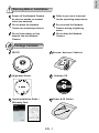
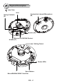
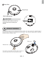
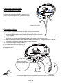
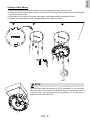
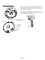
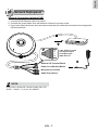
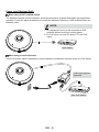
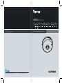
Dome
FE8172 Fixed
Network Camera
Quick Installation Guide
P/N:625018100G Rev.: 1.0
6F, No.192, Lien-Cheng Rd., Chung-Ho, New Taipei City, 235, Taiwan, R.O.C.
|T: +886-2-82455282| F: +886-2-82455532| E: [email protected]
繁中
Dansk
Indonesia
簡中
日本語
Français
Español
Deutsch
Português
5MP • 360° Surround View • PoE
All specifications are subject to change without notice.
Copyright c 2012 VIVOTEK INC. All rights reserved.
VIVOTEK INC.
English
VIVOTEK USA, INC.
2050 Ringwood Avenue, San Jose, CA 95131
|T: 408-773-8686| F: 408-773-8298| E: [email protected]
Italiano
Türkçe
Polski
Русский
Česky
Svenska
Dutch
English
Warning Before Installation
Refer to your user's manual
for the operating temperature.
Do not place the Network
Camera on unsteady surfaces.
Do not touch the Network
Camera during a lightning
storm.
Do not insert sharp or tiny
objects into the Network
Camera.
Do not drop the Network
Camera.
Package Contents
Screws / Anchors / Cable tie
FE8172
Alignment Sticker
Software CD
D r i ll h o l e
D ri ll h o l e
1
Power off the Network Camera
as soon as smoke or unusual
odors are detected.
510000210G
Quick Installation Guide /
Warranty Card
Power & I/O Cables
EN - 1
2
Physical Description
Inner View
Spring Contacts
(A)
Lens
Contacts for Internal Microphone
(B)
Header (J6)
Ethernet 10/100 RJ45 Socket
Header (J7)
Cabling Cutout
Status LEDs
Reset Button
MicroSD/SDHC/SDXC Card Slot
EN - 2
English
Outer View
Dome Cover
Built-in Microphone
IMPORTANT:
083236
Record the MAC address under the
camera base before installing the
camera.
3
Hardware Installation
First, open the dome cover by pressing the release button. You may squeeze the opposite edge of
the dome cover if the dome cover does not come off easily. Then, follow the steps below to install the
camera to either a ceiling or a wall.
Slide cover
Release button
If you plan to route cables from the side of camera, remove the rubber slide cover from the dome cover.
EN - 3
Connecting Ethernet Cable
& the Power and IO Cable
J6
Connect the supplied power & IO cables if your
switch does not support PoE. Connect the white
header connectors to J6 and J7 on the camera.
J7
Power & IO Cable
Connecting Cables
If you need to route cables through the side opening, proceed with
the following:
1. Connect the Ethernet and the Power & IO cables. The Ethernet cable
is user-supplied.
2. Use an included cable tie to secure the Ethernet and IO cable to the base plate. Insert the cable
tie through the vertical mounting tab located on the edge of the cabling cutout.
3. Make a clearance between cables and the vertical mounting tab. Arrange the cables neatly to
avoid getting in the way when the dome cover is attached.
4. Cut the extra length from the cable tie.
If you route cables through a drill hole on
a wall/ceiling, simply route cables through
the cabling cutout.
Make a clearance
between cables and
the vertical tab
Ethernet
Power and IO
cables
Strain relief boot
It is recommended to remove the strain relief boot if your Ethernet cable
comes with one.
EN - 4
English
Ceiling or Wall Mount
1. Attach the supplied alignment sticker for the camera base to the a ceiling or wall.
2. Using the circles on the sticker, drill pilot holes into the ceiling. Then hammer the supplied plastic
anchors into the holes.
3. (Optional) Drill a cable hole on the ceiling/wall, and feed the cables through the hole.
4. Secure the camera base to the ceiling/wall with the supplied screws.
1
2
4
o le
Dr
i ll h
Dr
i ll h
ol e
Dr
ill h
Dr
ill h
ol e
D r i ll h o l e
o le
D ri l l h o l e
3
NOTE:
You may also install the camera to a U.S. standard 4 in. junction box.
You can align the camera’s curved slots with the mounting holes on
a junction box. Use diagonal mounting positions on the camera to
match those on a junction box.
EN - 5
Attach the Dome Cover
Install the plastic dome cover by aligning the snapfit tabs on the dome cover with the slotted tabs on the
camera base. Install the dome cover by pressing it
evenly to the camera base.
Make sure the dome cover and the base plate are
flush-aligned before pressing down. The dome cover is
secured using a snap-fit mechanism.
Slotted tabs
Dome cover
Snap-fit tabs
EN - 6
English
4
Network Deployment
General Connection (without PoE)
1. Connect RJ45 Ethernet cable to a switch.
2. Connect the power cable from the Network Camera to a power outlet.
3. If you have external devices such as sensors and alarms, make the connection from the general
I/O terminal block.
POWER
COLLISION
1
2
3
4
1
3
+3V3
DO
D1
GND
+3V3: Power, 3.3V DC
DO: Digital Output
D I: Digital Input
GND: Ground
2
General I/O Terminal Block
Power Cord Socket (Black)
Microphone In (Pink)
Audio Out (Green)
NOTE:
If DC power is preferred, it should comply with: O/P:
12VDC, 1.5Amin., L.P.S. per IEC 60950-1.
EN - 7
5
LINK
RECEIVE
PARTITION
Power over Ethernet (PoE)
When using a PoE-enabled switch
The Network Camera is PoE-compliant, allowing transmission of power and data via a single Ethernet cable. Follow the below illustration to connect the Network Camera to a PoE-enabled switch via
Ethernet cable.
NOTE:
1. This equipment is only to be connected to PoE
networks without routing to outside plants.
2. For PoE input, use only UL listed I.T.E. with PoE
output.
POWER
COLLISION
1
2
3
4
5
LINK
RECEIVE
PARTITION
PoE Switch
When using a non-PoE switch
Use a PoE power injector (optional) to connect between the Network Camera and a non-PoE switch.
PoE Power Injector
(optional)
POWER
COLLISION
1
2
3
4
5
LINK
RECEIVE
PARTITION
Non-PoE Switch
EN - 8
English
5
Assigning an IP Address
1. Install “Installation Wizard 2” from the Software Utility directory on the software CD.
2. The program will conduct an analysis of your network environment. After your network is
analyzed, please click on the “Next” button to continue the program.
3. The program will search for VIVOTEK Video Receivers, Video Servers, and Network Cameras
on the same LAN.
4. After a brief search, the main installer window will pop up. Double-click on the MAC address
that matches the one printed on the camera label or the serial number on the package box label
to open a browser management session with the Network Camera.
6
Ready to Use
1. A browser session with the Network Camera should prompt as shown below.
2. You should be able to see live video from your camera. You may also install the 32-channel
recording software from the software CD in a deployment consisting of multiple cameras. For its
installation details, please refer to its related documents.
For further setup, please refer to the user's manual on the software CD.
NOTE:
If you encounter problems with displaying live view or the onscreen plug-in control, you may try to
remove the plug-ins that might have been installed on your computer. Remove the following folder: C:\
Program Files (x86)\Camera Stream Controller\.
EN - 9
Dome
FE8172 Fixed
Network Camera
Quick Installation Guide
P/N:625018100G Rev.: 1.0
6F, No.192, Lien-Cheng Rd., Chung-Ho, New Taipei City, 235, Taiwan, R.O.C.
|T: +886-2-82455282| F: +886-2-82455532| E: [email protected]
繁中
Dansk
Indonesia
簡中
日本語
Français
Español
Deutsch
Português
5MP • 360° Surround View • PoE
All specifications are subject to change without notice.
Copyright c 2012 VIVOTEK INC. All rights reserved.
VIVOTEK INC.
English
VIVOTEK USA, INC.
2050 Ringwood Avenue, San Jose, CA 95131
|T: 408-773-8686| F: 408-773-8298| E: [email protected]
Italiano
Türkçe
Polski
Русский
Česky
Svenska
Dutch