1
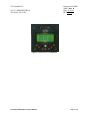
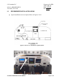
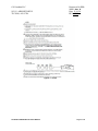
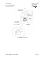
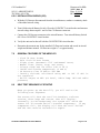
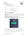
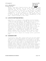
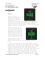
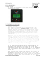
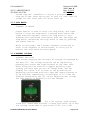
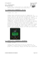
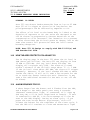
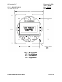
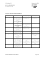
Document No.553-1000 Rev A. Date: 11-16-10 REV ORIG. CO Guardian LLC 1951 E. AIRPORT DRIVE TUCSON, AZ. 85706 Owner’s Manual For Model Aero-553 (Rev. A.) Document: 553-1000 Rev A. 553 MODEL OWNERS/INSTALLATION MANUAL Page 1 of 30 CO Guardian LLC 1951 E. AIRPORT DRIVE TUCSON, AZ. 85706 Document No.553-1000 Rev A. Date: 11-16-10 REV ORIG. INTENIONALLY LEFT BLANK 553 MODEL OWNERS/INSTALLATION MANUAL Page 2 of 30 Document No.553-1000 Rev A. Date: 11-16-10 REV ORIG. CO Guardian LLC 1951 E. AIRPORT DRIVE TUCSON, AZ. 85706 LOG OF REVISIONS REV NO. PAGE NO. DATE DESCRIPTION Orig. 1 thru 15 12/04/06 Initial Release ASH VIJ 1 thru 30 11/17/10 Pages 1 to 30 ASH VIJ APPROVED A 553 MODEL OWNERS/INSTALLATION MANUAL Page 3 of 30 CO Guardian LLC Document No.5531000 Rev A. Date: 11/16/10 REV ORIG. 1951 E. AIRPORT DRIVE TUCSON, AZ. 85706 TABLE OF CONTENTS LOG OF REVISIONS ................................................................................................................................................. 3 TABLE OF CONTENTS ......................................................................................................................................... 4 FORWARD ................................................................................................................................................................. 5 DESCRIPTION ........................................................................................................................................................... 6 1.0 GENERAL .................................................................................................................................................... 6 2.0 PHYSICAL DESCRIPTION ......................................................................................................................... 6 TABLE 1 - Part Numbers ........................................................................................................................................ 6 3.0 LEADING PARTICULARS ........................................................................................................................... 7 TABLE 2 - Leading Particulars ................................................................................................................................ 7 4.0 SCOPE ........................................................................................................................................................ 8 5.0 SERVICE FACILITIES ................................................................................................................................. 9 6.0 INSTALLATION ........................................................................................................................................... 9 6.1 RECOMMENDED INSTALLATION AREAS .............................................................................................. 11 FIGURE 2 - TYPICAL RIGHT INSTRUMENT PANEL ......................................................................................... 11 FIGURE 4 - NOTES .............................................................................................................................................. 12 6.2 INSTALLATION INSTRUCTIONS ............................................................................................................. 12 6.2.1 INSTALLATION INSTRUCTIONS ...................................................................................................... 14 6.2.2 INSTALLATION CHECKS ..................................................................................................................... 15 7.0 GENERAL FEATURES OF THE AERO 553 ............................................................................................. 25 8.0 SELF TEST SEQUENCE AT STARTUP ................................................................................................... 15 9.0 CO LEVEL ALARM ACTIVATION ............................................................................................................. 26 10.0 EFFECTS OF CO IN HUMAN BODY .................................................................................................... 16 11.0 LAYOUT OF BUTTONS/CONTROLS ................................................................................................... 17 12.0 ALARM INDICATOR .............................................................................................................................. 17 13.0 FUNCTIONS/FEATURES ...................................................................................................................... 18 13.1 LOCAL AND ZULU TIME ....................................................................................................................... 18 13.2 AUTOMATIC FLIGHT TIME .................................................................................................................. 19 13.3 STOP WATCH ....................................................................................................................................... 20 13.4 BATTERY VOLTAGE ............................................................................................................................ 20 13.5 INSIDE/OUTSIDE TEMPERATURE (CELSIUS) ................................................................................... 21 13.6 INSIDE/OUTSIDE TEMPERATURE (FAHRENHEIT) ........................................................................... 21 13.7 CABIN ALTITUDE .................................................................................................................................. 22 13.8 CARBON MONOXIDE LEVEL INDICATION ......................................................................................... 23 14.0 HOW THE AERO 553 PROTECTS YOU AGAINST CO ....................................................................... 23 15.0 ALARM SEQUENCE FOR CO .............................................................................................................. 23 16.0 DENSITY ALTITUDE ............................................................................................................................. 24 17.0 TECHNICAL SPECIFICATIONS............................................................................................................ 24 18.0 SELF TEST SEQUENCE ....................................................................................................................... 24 19.0 UNIT FAILURE INDICATION ................................................................................................................. 24 20.0 INTERFACE WITH MFD’S .................................................................................................................... 25 21.0 END OF LIFE ......................................................................................................................................... 25 22.0 MAINTENANCE INSTRUCTIONS ......................................................................................................... 25 23.0 CARBON MONOXIDE DETECTOR SCHEDULE MAINTENANCE ...................................................... 26 24.0 WEIGHT AND BALANCE / EQUIPMENT LIST ..................................................................................... 26 25.0 LIMITATIONS......................................................................................................................................... 27 26.0 NORMAL PROCEDURES ..................................................................................................................... 27 27.0 PERFORMANCE ................................................................................................................................... 27 28.0 EMERGENCY PROCEDURES ............................................................................................................. 27 29.0 WARRANTY........................................................................................................................................... 28 553 MODEL OWNERS/INSTALLATION MANUAL Page 4 of 30 CO Guardian LLC Document No.5531000 Rev A. Date: 11/16/10 REV ORIG. 1951 E. AIRPORT DRIVE TUCSON, AZ. 85706 FORWARD This document provides information intended for use by persons who, pursuant to current requirements, are qualified to install this equipment. Because equipment and system installations vary depending on a particular aircraft, this document is intended only as a guideline. If further information is required, contact: CO Guardian, LLC 1951 E. Airport Drive Tucson, AZ 85706 (520) 889-1177 (800) 639-7139 www.coguardian.com We welcome your comments concerning this document. Although every effort has been made to keep it free of errors, some may occur. When reporting a specific problem, please describe it briefly and include the document number, the paragraph/figure/table number, and the page number. Send your comments to the address above. 553 MODEL OWNERS/INSTALLATION MANUAL Page 5 of 30 CO Guardian LLC Document No.5531000 Rev A. Date: 11/16/10 REV ORIG. 1951 E. AIRPORT DRIVE TUCSON, AZ. 85706 DESCRIPTION 1.0 GENERAL This section gives a physical and functional description of the CO Guardian 553 CO Detector unit (AERO-553) as installed in a typical reciprocating engine type aircraft. See physical description below. 2.0 PHYSICAL DESCRIPTION (AERO-553) Panel mounted 553 CO Detector part numbers are listed in Table 1. PART Description SERVICE RS232 POWER NUMBER LIFE Output for Volts MFD (CO, Pressure, Cabin Temp 553 Panel mount 5 years Yes 14/28 Detector Table 1 - Part Numbers Cabin Pressure warning Light at (10K) Yes The Detector must be returned to CO Guardian at the end of Service Life for replacement and calibration of the CO sensor to maintain airworthiness of the unit. NOTE: The main reason for replacement of the sensor is the degradation of the sensor and dirt accumulation over the years. See www.coguardian.com for exact procedures. 553 MODEL OWNERS/INSTALLATION MANUAL Page 6 of 30 CO Guardian LLC Document No.5531000 Rev A. Date: 11/16/10 REV ORIG. 1951 E. AIRPORT DRIVE TUCSON, AZ. 85706 3.0 LEADING PARTICULARS Table 2 CO Detector leading particulars and specs. LEADING PARTICULARS/SPECS PARAMETER SPECIFICATION PHYSICAL Dimensions (approximate) 2.63” long. X 2.6”wide x 1.88” height Weight (actual) 7.0 oz. ENVIRONMENTAL Cooling Passive Temperature and Altitude Temperature Non-operating high temperature +85 °C Non-operating low temperature -55 °C Operating high temperature Operating low temperature +65 °C -20 °C Temperature Variation Altitude Compensation with built in Pressure sensor 25,000’ Humidity 95% POWER REQUIREMENTS Power – 14/28 VDC Models Nominal 9.0 vdc to 30.3vdc Dissipation (maximum) <1 watt Table 2 Leading Particulars 553 MODEL OWNERS/INSTALLATION MANUAL Page 7 of 30 CO Guardian LLC 1951 E. AIRPORT DRIVE TUCSON, AZ. 85706 4.0 SCOPE Document No.5531000 Rev A. Date: 11/16/10 REV ORIG. The Model 553 Carbon Monoxide Detector is designed to detect, measure, and provide a visual alert to the crew before the cockpit level of carbon monoxide (CO) reaches a critical level, Aero 553 is a sophisticated Carbon Monoxide detector designed for general Aviation. It has many additional features making it a truly Multi Function CO detector. Besides detecting carbon monoxide and thus protecting the pilot and the passengers, it is also designed to replace the standard aircraft clock and fits into a 2.25 inch circular cutout. Aero 553 replaces Aero 552 and now displays CO level from 05 PPM. Being a truly multi function device, the Aero 553 has many features and functions. You can scroll between different functions, but the unit reverts to the local time mode after 45 seconds of inactivity in any function or display other than if you are on the stop watch page. More-over, irrespective of which function or display the unit is presently in, if any alarm conditions like dangerous levels of CO are triggered, the unit reverts automatically to the page / display relevant to that alarm. The carbon monoxide alarm level is calibrated to provide a visual alert within 5 minutes or less whenever the carbon monoxide level reaches 50 parts per million (PPM) by volume or greater. The warning time is shortened at higher levels of CO concentrations and becomes approximately instant should the carbon monoxide level reach 400 parts per million by volume (PPM) or greater. In case of a carbon monoxide alert, the pilot will receive an Alert message on the 553’s display screen or on the Pilot's instrument panel MFD. The visual alert will remain until the carbon monoxide level is reduced below the alert level. The indicator is automatically reset when the CO level drops below 50 PPM. There is a three-minute delay at startup to stabilize the sensor before the unit will accurately sense CO levels. The 553 has a built in pressure compensation sensor to detect cabin altitude changes up to 25,000 to give a better accuracy in CO Detection. This model also alarms if the cabin altitude goes above 10,000 feet. This model has RS232 output for display data of CO Level on Electronics International, Advanced Flight Technologies, Grand Rapids Instruments, and Avidyne Entegra Release 9. See website www.coguardian.com to see the latest manufacturers capable of showing data on Multi Function Displays. 553 MODEL OWNERS/INSTALLATION MANUAL Page 8 of 30 CO Guardian LLC 1951 E. AIRPORT DRIVE TUCSON, AZ. 85706 5.0 Document No.5531000 Rev A. Date: 11/16/10 REV ORIG. SERVICE FACILITIES (all models) The operator can service all other components of the installation at an FAA certified Repair Station or by an A&P mechanic. CO Detectors must me be returned to CO Guardian for repair, calibration or overhaul. The sensor life is 5 years from date of installation. NOTE The sensor requires special gases for testing. If any discrepancies are found with the unit during installation or during the operational service life, the unit must be returned to CO Guardian for repair or replacement. The CO Detector unit must be returned to the manufacturer for CO sensor replacement and re-calibration at the end of the service life applicable to the unit’s part number. 6.0 INSTALLATION 553 Install Aero-553 per CO Guardian installation drawing number 01-553-01-IR (Or later revision) for hardware and wiring diagram installation. Use MFG of MFD drawings in connecting via RS-232. a. Choose a location in the instrument panel for the installation of the CO Detector with space available that meets the following criteria. The middle section of the instrument panel is recommended since the unit has to be reached by both pilot and co-pilot for usage. b. Insure that the area around the CO Detector panel location will permit unrestricted airflow through the unit. c. Install in a cockpit area not exposed to excessively dusty or dirty conditions. d. Insure that the air intake on the front of the CO Detector is not obstructed in any manner. e. Install the CO Detector in a location without high or disturbed airflow movement. The CO Detector will detect the presence of CO more effectively if the unit does not have air blowing over it. f. Insure that the CO Detector installation area meets the temperature and humidity ranges listed in the List of Particulars specifications (Table 2). Temperature and humidity conditions outside the specification may affect the sensitivity of the detector. g. The AERO-553 unit can be installed anywhere around the instrument panel within both pilots reach. Verify that there is no obstruction of airflow to the unit. 553 MODEL OWNERS/INSTALLATION MANUAL Page 9 of 30 CO Guardian LLC Document No.5531000 Rev A. Date: 11/16/10 REV ORIG. 1951 E. AIRPORT DRIVE TUCSON, AZ. 85706 Figure 1 AERO-553 CO detector 553 MODEL OWNERS/INSTALLATION MANUAL Page 10 of 30 CO Guardian LLC Document No.5531000 Rev A. Date: 11/16/10 REV ORIG. 1951 E. AIRPORT DRIVE TUCSON, AZ. 85706 6.1 RECOMMENDED INSTALLATION AREAS Typical installation areas are depicted below in Figurers 3 & 4. Figure 2 AERO-553 installed in typical panel Figure 3 Typical installation shown 553 MODEL OWNERS/INSTALLATION MANUAL Page 11 of 30 CO Guardian LLC Document No.5531000 Rev A. Date: 11/16/10 REV ORIG. 1951 E. AIRPORT DRIVE TUCSON, AZ. 85706 Figure 4. Notes. 553 MODEL OWNERS/INSTALLATION MANUAL Page 12 of 30 CO Guardian LLC Document No.5531000 Rev A. Date: 11/16/10 REV ORIG. 1951 E. AIRPORT DRIVE TUCSON, AZ. 85706 Figure 5. Section B-B 553 MODEL OWNERS/INSTALLATION MANUAL Page 13 of 30 CO Guardian LLC Document No.5531000 Rev A. Date: 11/16/10 REV ORIG. 1951 E. AIRPORT DRIVE TUCSON, AZ. 85706 6.2 INSTALLATION INSTRUCTIONS 6.2.1 INSTALLATION INSTRUCTIONS (AERO-553). Referee to Drawing # 01-553-01 (at www.coguardian.com). a. Install the CO Detector in accordance with Figures 3 Section B-B. b. Install the CO Detector 2 amp circuit breaker in accordance with Figure 3 Section A-A. It is recommended that the circuit breaker be installed on the Essential or Avionics Buss that is not subject to emergency electrical load shedding. Placard or engrave the circuit breaker as CO DETECT in accordance with Figure 5, Flag Note 11. c. Wire the CO Detector installation in accordance with Drawing # 01-553-01, page 3. PIN 1 2 3 4 5 6 7 8 9 10 11 12 13 14 553 FUNCTION Power Wire RS-232 In Spare Ground Cabin Pressure Temperature Probe (+) Remote Reset Test Audio Tone Generator Power Ground RS-232 Out CO Alert Light Voice Activate (optional) NC Temperature Probe (-) 553 CO DETECTOR CONNECTOR FIFTEEN PIN PINOUT Observe the following items: Twist the power and ground return wires together approximately 6 turns per foot in accordance with Figure 6, Note 7. Connect Pin 1 to +14 VDC or to +28 VDC power as applicable to the installation aircraft and the CO Detector voltage rating. Ground power return wire (Pin 9) to suitable aircraft structure ground near circuit breaker panel. 553 MODEL OWNERS/INSTALLATION MANUAL Page 14 of 30 CO Guardian LLC 1951 E. AIRPORT DRIVE TUCSON, AZ. 85706 6.2.2 INSTALLATION CHECKS (553) Document No.5531000 Rev A. Date: 11/16/10 REV ORIG. a. With the CO Detector disconnected from the aircraft harness, conduct a continuity check of the added aircraft wiring. b. Turn ON the aircraft Battery Switch. Close the CO DETECT circuit breaker and measure aircraft voltage between pins 1 and 9 of the CO Detector connector. c. Connect the CO Detector connector to the aircraft harness. Turn aircraft Battery Switch ON. Close CO DETECT circuit breaker. d. Verify the unit can be shut off with the CO DETECTOR circuit breaker. e. Determine the moment arm for the installed CO Detector location and record in aircraft weight and balance manual. CO Detector weight is 7 oz approximately. 7.0 GENERAL FEATURES OF THE AERO-553 - Clock 24 Hour Format - Zulu clock 24 hour format - Flight timer (Automatic 150’ and Manual Start) - Manual Timer (Start, stop, and reset) - Voltage (High and low alarm (14V or 28 V) - Inside and outside temperature (F and C) - CO Detector form 10 PPM to 999 PPM - Density altitude calculated using OAT or IAT if OAT is not connected - RS-232 output on MFD (CO Level, Cabin Temp. OAT and cabin pressure) 8.0 SELF TEST SEQUENCE AT STARTUP When you power up the Aero-553, you will notice the following test sequence: The screen will show the word “CO Guardian, software version, short beep and current time will display. Internally in the background, the system will check the sensor for 30 seconds and all internal components. If any components fail, the display will show the word “Failed” and the unit must be returned for repair. 553 MODEL OWNERS/INSTALLATION MANUAL Page 15 of 30 CO Guardian LLC Document No.5531000 Rev A. Date: 11/16/10 REV ORIG. 1951 E. AIRPORT DRIVE TUCSON, AZ. 85706 9.0 CO LEVEL ALARM ACTIVATION CO level alarm activated after: in PPM (Parts per million) PPM 10 - 50 50 – 70 70 - 100 200 300 >400 10.0 Display only No alarm 04 minutes Alarm mode 03 minutes Alarm mode 02 minutes Alarm mode 01 minutes Alarm mode 15 seconds Alarm mode EFFECTS OF CO IN HUMAN BODY NOTE: Concentration of CO in air Inhalation time and toxic developed 50 parts per million (PPM) Safety level as specified by the FAA 200 PPM Slight headache within 2-3 hours 400 PPM Frontal headache within 1-2 hours 800 PPM Dizziness, nausea, convulsions within 45 minutes Aero 553 is a sophisticated Carbon Monoxide detector designed for general Aviation. It has many additional features making it a truly Multi Function CO detector. Besides detecting carbon monoxide and thus protecting the pilot and the passengers, it is also designed to replace the standard aircraft clock and fits into a 2.25 inch circular cutout. Aero 553 replaces Aero 552 and now displays CO level from 05 PPM. 553 MODEL OWNERS/INSTALLATION MANUAL Page 16 of 30 CO Guardian LLC Document No.5531000 Rev A. 1951 E. AIRPORT DRIVE Date: 11/16/10 TUCSON, AZ. 85706 REV ORIG. Being a truly multi function device, the Aero 553 has many features and functions. You can scroll between different functions, but the unit reverts to the local time mode after 45 seconds of inactivity in any function or display other than if you are on the stop watch page. More-over, irrespective of which function or display the unit is presently in, if any alarm conditions like dangerous levels of CO are triggered, the unit reverts automatically to the page / display relevant to that alarm. 11.0 LAYOUT OF BUTTONS/CONTROLS: Model 553 is a CO Detector that Display CO Level between 10PPM (Parts per Million) to 999PPM. The Aero 553 features a 1.75 x 1 inch LCD display. The display is backlit continuously. There are basically 4 buttons which can be used to control the displays and adjust the settings on the unit: The red button at the top (marked “RST”) is the Test/Re-set button which can be used to test or re-set the unit. There are 3 buttons at the bottom, which will be referred to in this manual by the terms “Left Button” (marked “SC”), “Center Button” (marked “ST”), and “Right Button” (marked “SP”). The left button is used to scroll between different functions/pages. The center and right buttons are used to adjust the settings inside a particular page. 12.0 ALARM INDICATOR A yellow/red light (LED) coupled with an 85 DB audio beeper constitute the primary mechanism for indicating an alarm. An alert is also accompanied by 4 short beeps to the audio panel. A yellow alert light is for CO Levels between 50-100 PPM, and a red alert light for 100 PPM and above. Other external alert indications include lighting up of the external Remote light (if connected), and relevant messages displayed on multi-function display like (G1000, GNS480, EI-50 and others). Please refer to the last page to see an overview of the various alarms and the individual functions listed below to determine when an alarm will be triggered. 553 MODEL OWNERS/INSTALLATION MANUAL Page 17 of 30 CO Guardian LLC 1951 E. AIRPORT DRIVE TUCSON, AZ. 85706 13.0 FUNCTIONS/FEATURES: Document No.5531000 Rev A. Date: 11/16/10 REV ORIG. 13.1 LOCAL & ZULU DISPLAY: HH:MM LC HH:MM ZU This is the first display and the default display. It shows the local time and Zulu time simultaneously. The reading is in a 24 hour format (HH:MM). This display is to be initially set by the user. However, the readings are stored in the unit with the help of a small in-built battery, and so the time is stored even when the main power supply to the unit is turned off. In order to adjust Local time, first press the right “SP” and center button “ST” at the same time and hold it depressed for 5 seconds. An arrow pointing to the local time will appear as seen on the picture below; you are now in change mode for local time. You can set the hour with the center button, and minutes with the right button. After you have set the time press the scroll button. To enter adjustment mode for Zulu time, repeat the same process as for local time. Press center “ST” and right “SP” buttons twice to select the Zulu time, an arrow will appear pointing the Zulu time as seen on the picture below; you are now in change mode for Zulu time. Hour and minute changes are made just like in local time. After you set the time press the scroll button (left button “SC”). When crossing a local time zone during flight, you need to manually adjust the local time to the new local time by toggling to this display and setting the new local time. Since Zulu time corresponds to GMT which does not change, 553 MODEL OWNERS/INSTALLATION MANUAL Page 18 of 30 CO Guardian LLC Document No.5531000 Rev A. 1951 E. AIRPORT DRIVE Date: 11/16/10 TUCSON, AZ. 85706 REV ORIG. no changes are necessary to Zulu time even while crossing different time zones. 13.2 AUTOMATIC FLIGHT TIME DISPLAY: FLT TIME This page is a convenient way to measure flight time. This page is pre-set to automatic mode, so that after takeoff, when the aircraft is 150 feet above the airport elevation after power startup, the flight time recorder turns ON by itself automatically. The unit can also be started manually anytime by pressing the center button labeled “ST”. However it will not turn itself OFF automatically after landing. Stopping has to be done manually by pressing the right button “SP”. (This will stop the flight timer, but will not re-set it to zero.) Re-starting is done pressing the center button, which starts it from where it left off last. To reset the flight timer to zero, press center and right buttons together. Re setting to zero can be done while it is running or while it is stopped. If you press the Test/Re-set button (top red button) for any reason like canceling a CO alarm, the flight timer continues to record and is not turned off. It is turned off (and also resets to Zero) when power supply to the unit is turned off. Also note that auto flight timer kicks in only when it is NOT manually selected on, like on the first flight after start-up. If after the first flight, you do not stop/re-set the flight timer to Zero, auto start will not kick in on 553 MODEL OWNERS/INSTALLATION MANUAL Page 19 of 30 CO Guardian LLC Document No.5531000 Rev A. 1951 E. AIRPORT DRIVE Date: 11/16/10 TUCSON, AZ. 85706 REV ORIG. second take-off. Therefore it may be a good practice to stop the flight timer and re-set to zero for each take off except for the first take off after start up. 13.3 STOP WATCH DISPLAY: ST WATCH Center button is used to start the stop watch, and right button to stop the stop-watch. Pressing both center and right buttons together, resets the stop watch to Zero. Pressing the top button (Test-Rest) does not interrupt the stop watch. Restarting the stop watch is done by pressing the center button. While on this page, the 5 minute automatic reverting to Local clock sequence is de-activated, to allow you to monitor the stop watch un-interrupted. 13.4 BATTERY VOLTAGE DISPLAY: BAT VOLT This screen displays the aircraft DC voltage as measured by the Aero 553. The voltage read-out can be adjusted by pressing the center and right buttons at the same time. After doing this an arrow will appear pointing right letting you know that you are on change mode, and the display will show “0.0” as seen on the picture below. Adjusting can be made with the right and center buttons to go up and down respectively in multiples of 0.1 from the read-out measured by the 553. After adjusting the voltage the left button is pressed to set the changes. For a 14V system, high voltage alarm will sound when aircraft voltage goes above 14.1V and low voltage alarm when it goes below 11.9V. For a 28V 553 MODEL OWNERS/INSTALLATION MANUAL Page 20 of 30 CO Guardian LLC Document No.5531000 Rev A. 1951 E. AIRPORT DRIVE Date: 11/16/10 TUCSON, AZ. 85706 REV ORIG. system, high voltage alarm will sound when it goes above 28.2V and the low voltage alarm below 23.9V. 13.5 INSIDE/OUTSIDE TEMPERATURE (CELSIUS) DISPLAY: IAT / OAT Display shows inside and out-side air temperature in Celsius. Read-out can be adjusted by pressing the right and center buttons at the same time. An arrow will appear letting you know that you are on change mode. To go up and down the right and left buttons are used respectively. Temperature is adjusted having the unit’s read-out for temperature as point of reference. For example is the unit is reading 3 degrees Celsius and the actual temperature is known to be 0 degrees Celsius (this can be checked performing an ice bath to the probe) the adjustment needed would be clicking the “ST” button three times to go down 3 degrees lower to what the actual reading is. If the OAT probe is not connected, display will show xxxx against OAT. 13.6 INSIDE/OUTSIDE TEMPERATURE (FAHRENHEIT) DISPLAY: IAT/OAT Display shows inside and out-side air temperature in Fahrenheit. Read-out cannot be adjusted, but if the OAT probe is not connected, display will show xxxx against OAT. 553 MODEL OWNERS/INSTALLATION MANUAL Page 21 of 30 CO Guardian LLC 1951 E. AIRPORT DRIVE TUCSON, AZ. 85706 13.7 CABIN ALTITUDE Document No.5531000 Rev A. Date: 11/16/10 REV ORIG. DISPLAY: CAB ALT Display shows cabin altitude in feet. It can be adjusted or re-set by pressing the right and center buttons at the same time. An arrow pointing right will appear letting you know that you are on change mode as seen on the picture below. The altitude is adjusted the same way as the previous functions. Use the right and center buttons to go up and down respectively. After the adjustments have been made left button is pressed to set the changes. The device is programmed to alert the pilot when going above pre-set cabin altitudes, to facilitate switching on to breathing oxygen. If cabin altitude rises above 10,000 ft, an alert will be sounded. The 10,000 ft alert will be de-activated thereafter, till the cabin altitude drops below 8000 feet. This is to prevent frequent setting off of this alarm, especially if you happen to fly close to 10,000 ft where you frequently go slightly above or below 10,000 ft. The alert will sound again if the cabin altitude stays above 12,500 ft for 30 minutes. If cabin altitude rises above 14,000 ft, another alert will be sounded. Note: All altitude warnings are momentary and no action is required by pilot. 553 MODEL OWNERS/INSTALLATION MANUAL Page 22 of 30 CO Guardian LLC 1951 E. AIRPORT DRIVE TUCSON, AZ. 85706 13.8 CARBON MONOXIDE LEVEL INDICATION Document No.5531000 Rev A. Date: 11/16/10 REV ORIG. DISPLAY: CO LEVEL Aero 553 can detect Carbon Monoxide from as low as 05 PPM. Aero 553 will trigger an alarm for CO long before the pilot/passengers can be affected by exposure to CO. The effect of CO level on the human body is linked to the duration of exposure to CO. Our units are designed to set off CO alarms in progressively shorter durations as the concentration of CO increases. The intention is to prevent a false alarm when the CO level poses no danger, but at the same time ensure full protection when the level starts becoming dangerous. NOTE: Aero 553 IS design to comply with FAR 23.831(a) and SAE Standard AS 412A. 14.0 HOW THE AERO PROTECTS YOU AGAINST CO The CO display page in the Aero 553 shows the CO level in PPM (Parts per million). The Aero-553 can display CO from 10 PPM to 999 PPM. (For any level above 999 PPM, the display will register only 999). The alarm will sound within 5 minutes if the CO level stays above 75 +/- 5 PPM. If the CO level rises above 400 PPM, the alarm will trigger instantly. (However, if the level reaches 400 PPM or above inside the cabin, it will still take a few seconds for the CO to reach the sensor inside the unit. Therefore it may take a few additional seconds for the unit to set off the CO alarm). 15.0 ALARM SEQUENCE FOR CO: 4 short beeps from the buzzer and 4 flashes from the LED, and 4 beeps to the audio panel once every 4 seconds. (External annunciator light, if connected, will light up and stay ON, till CO level drops back to normal). If unit is connected to CNX 80, a CO alert message will also be sent to the CNX display. During an alarm cycle, if you press the test/re-set button (top button), this will silence the buzzer for the remainder of the alarm cycle, 8 but the LED will continue to flash and annunciator light 553 MODEL OWNERS/INSTALLATION MANUAL Page 23 of 30 CO Guardian LLC Document No.5531000 Rev A. 1951 E. AIRPORT DRIVE Date: 11/16/10 TUCSON, AZ. 85706 REV ORIG. will remain ON, till alarm conditions for CO level no longer persist. 16.0 DENSITY ALTITUDE DISPLAY: DEN ALT The density altitude is calculated using the absolute pressure and the Outside Air Temp. This cannot be adjusted manually. The display is in feet. (Since Outside Air Temperature is a necessary input for this calculation, if an OAT probe is not connected, the unit will read inside cabin temperature in calculating the Density Altitude automatically. NOTE: It’s highly recommended that OAT probe be connected for greater accuracy. Density Altitude is guide, pilot should use other information in calculating the aircraft performance. 17.0 18.0 TECHNICAL SPECIFICATIONS Power supply: 12 - 30 V DC Power consumption: 2 W Current drawn: 300 milli-amps Fuse: Use GMI type, fast acting fuse 2A 250V Temperature range: -20C to +65C Humidity range: 10-90% RH (Non condensing) Sensor calibration: Each unit calibrated at 75 PPM Weight of the unit SELF TEST SEQUENCE When you press the test/re-set button, the buzzer will beep 2 times, and the yellow light will flash twice. The external light (If connected) will flash 2 times. This sequence will indicate that the unit is in functional condition. 19.0 UNIT FAILURE INDICATION Malfunction of the Carbon Monoxide detection mechanism, will be indicated by a constantly glowing LED, and a display message of “FAILURE” in the CO level page. Please contact CO Guardian LLC for technical help if the problem persists. 553 MODEL OWNERS/INSTALLATION MANUAL Page 24 of 30 CO Guardian LLC 1951 E. AIRPORT DRIVE TUCSON, AZ. 85706 20.0 Document No.5531000 Rev A. Date: 11/16/10 REV ORIG. INTERFACE WITH MFD’S Aero 553 has an output which is compatible with RS-232 and it can interface with GNS480, Garmin 1000, G9000, Electronic Instruments EI-50 and other MFD’s. See website www.coguardian.com for current capabilities installed on your aircraft. The CO level, Inside Air Temp and Outside Air Temp are transmitted by the Aero 553 to the once MFD’s every second. Depending on the MFG software capabilities, the unit will display CO Level, Cabin Temperature, Cabin Pressure and Outside Air Temperature. 21.0 END OF LIFE The Aero 553 has a built in clock that is designed to shut itself after 5 years of service life. This is done to protect the occupants of the cabin and assume unit accuracy. The clock is started when the unit is activated when aircraft starts flying after initial install for 30 minutes. 22.0 MAINTENANCE INSTRUCTIONS The carbon monoxide detector and associated equipment consist of certain parts, which do not require periodic scheduled servicing or periodic scheduled preventive maintenance. At every power up the system will go through a self-diagnostic check. Field repair or service is allowable on all of the installed system components except for the CO Detector Indicator itself. The CO Detector must be returned to CO Guardian, LLC for all service. The aircraft wiring harness and circuit breaker shall be included maintenance instructions for general visual inspections for system integrity, installation security, corrosion and chaffing. 553 MODEL OWNERS/INSTALLATION MANUAL Page 25 of 30 CO Guardian LLC Document No.5531000 Rev A. 1951 E. AIRPORT DRIVE Date: 11/16/10 TUCSON, AZ. 85706 REV ORIG. 23.0 CARBON MONOXIDE DETECTOR SCHEDULED MAINTENANCE Scheduled Maintenance Program tasks to be added to the aircraft operator's appropriate airplane maintenance program are as follows: MAINTENANCE TASK INTERVAL a. Recommended Periodic Scheduled Servicing Tasks: None Required. b. Recommended Periodic Scheduled Preventative Maintenance Each time the unit is turned ON. test/checks to determine system condition and/or latent failures: Note: Be sure the vent on the faceplate is free of obstructions. c. Recommended Periodic Inspections: None Required. d. Recommended Periodic Structural Inspections None Required. e. Required CO Sensor replacement and calibration. At end of Service Life (Reference Par. 2.0) NOTE The unit must be returned to the manufacturer for sensor replacement and recalibration at the end of the unit service life. NO FIELD SERVICE OR OVERHAUL OF MODELS IS AUTHORIZED. 24.0 WEIGHT AND BALANCE / EQUIPMENT LIST The Aero 553 CO Detector installation weighs 7 oz. Reference the aircraft weight and balance manual for moment arm. 553 MODEL OWNERS/INSTALLATION MANUAL Page 26 of 30 CO Guardian LLC 1951 E. AIRPORT DRIVE TUCSON, AZ. 85706 25.0 LIMITATIONS Document No.5531000 Rev A. Date: 11/16/10 REV ORIG. The AERO-553 CO Detector may not replace any existing instrument or indicator required by the type design or operating limits. 26.0 NORMAL PROCEDURES When the airplane master battery switch is selected ON, the CO Detector goes through a self-test routine. The RS-232 MFD will show no CO on the CO Detector page. 27.0 PERFORMANCE No Change 28.0 EMERGENCY PROCEDURES If the CO Detector ALERT annunciator activates in flight: Shut off the heater, air conditioning or any other opening to the engine compartment. Open a fresh air source immediately. Don't smoke. Use 100% oxygen, if possible. Land as soon as conditions permit. Be sure the source of the contamination is corrected before further flight. NOTE: The alert message on the MFD will stay on until the CO level goes below 50 parts per million (PPM) by volume of carbon monoxide concentration. DO not recycle the unit through the circuit breaker. A three-minute delay is required for the CO sensor to stabilize after each power-up. 553 MODEL OWNERS/INSTALLATION MANUAL Page 27 of 30 CO Guardian LLC 1951 E. AIRPORT DRIVE TUCSON, AZ. 85706 29.0 WARRANTY Document No.5531000 Rev A. Date: 11/16/10 REV ORIG. LIMITED WARRANTY Unit comes with a 1 year limited warranty. The warranty will be void if the unit is opened or tampered with. WARRANTY COVERAGE: CO GUARDIAN LLC. WARRANTS TO THE ORIGINAL CONSUMER PURCHASER, THAT THIS DETECTOR WILL BE FREE OF DEFECTS IN MATERIAL AND WORKMANSHIP FOR A PERIOD OF 12 months FROM DATE OF PURCHASE. THE MANUFACTURER’S LIABILITY HEREUNDER IS LIMITED TO REPLACEMENT OF THE PRODUCT, REPAIR OF THE PRODUCT OR REPLACEMENT OF THE PRODUCT WITH REPAIRED PRODUCT AT THE DISCRETION OF THE MANUFACTURER. THIS WARRANTY IS VOID IF THE PRODUCT HAS BEEN DAMAGED BY ACCIDENT, UNREASONABLE USE, NEGLECT, TAMPERING OR OTHER CAUSES NOT ARISING FROM DEFECTS IN MATERIAL OR WORKMANSHIP. THIS WARRANTY EXTENDS TO THE ORIGINAL CONSUMER PURCHASER OF THE PRODUCT ONLY. Warranty Disclaimers: Any implied warranties arising out of this sale, including but not limited to the implied warranties of description, merchantability and fitness for a particular purpose, are limited in duration to the above warranty period. In no event shall the Manufacturer be liable for loss of use of this product or for any indirect, special, incidental or consequential damages, or costs, or expenses incurred by the consumer or any other user of this product, whether due to a breach of contract, negligence, strict liability in tort or otherwise. The manufacturer shall have no liability for any personal injury, property damage or any special, incidental, contingent or consequential damage of any kind resulting from gas leakage, fire or explosion. Some states do not allow limitations on how long an implied warranty lasts, so the above limitation may not apply to you. For Warranty Service: In case you experience any problems with the unit, you may contact our customer service department at 1-800-639-7139 for assistance. Even if you have purchased the unit from one of our distributors, you can contact us directly at the following address for technical support or in case you have any problems with your unit: CO Guardian LLC. 1951 East Airport Drive Tucson, AZ 85756 Tel 520-889-1177; Fax 520-889-8249; Email [email protected] 553 MODEL OWNERS/INSTALLATION MANUAL Page 28 of 30 CO Guardian LLC Document No.5531000 Rev A. Date: 11/16/10 REV ORIG. 1951 E. AIRPORT DRIVE TUCSON, AZ. 85706 RST = Re-Set Button SC = Scroll Button ST = Start Button SP = Stop Button 553 MODEL OWNERS/INSTALLATION MANUAL Page 29 of 30 CO Guardian LLC Document No.5531000 Rev A. Date: 11/16/10 REV ORIG. 1951 E. AIRPORT DRIVE TUCSON, AZ. 85706 Aero 553 -Various Alarm Indications: For Carbon Monoxide LED ( Flashing) LED (Steady ON) Buzzer Head set Remote light LCD Display MFD Displays For Battery Voltage For Cabin Altitude √ (4 flashes repeating till you press Re-set Button ) Yellow for 50-100PPM Red for 100PPM and above √ ( 4 flashes once ) √ ( 4 flashes once ) √ √ ( As long as Bat Volt is outside limits ) √ (4 beeps one time ) --- ( After re-setting, as long as alarm conditions persist) √ (4 beeps repeating till you press Re-set Button ) √ (4 beeps one time) √ ( Stays on , as long as CO alarm conditions persist ) √ Will switch to CO page, and remain there till 5 minutes past after CO level becomes normal √ ( Alarm Indication will show once ) 553 MODEL OWNERS/INSTALLATION MANUAL --- √ (4 beeps one time ) --- √ (4 beeps one time ) √ ( comes on for 10 seconds) √ Will stay on Bat volt page for 5 mts before returning to Local time --- √ Will stay on Cabin Alt page for 5 mts before returning to Local time --- Page 30 of 30