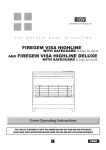
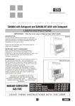
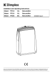
1
C
Dusk
Time
D
Installation
Lens Mask
IMPORTANT – Switch off the electricity at
Restrict long
detection
After choosing a suitable location (see previous
section) install the unit as follows:
Installation & Operating
Instructions
3000W
PIR LIGHT
CONTROLLER
Cat No. DX4131 – White
Restrict short
detection
Restrict RHS
detection
Restrict LHS
detection
Parts included
• PIR Sensor unit.
• Instruction manual. Please keep safe
for future reference.
• Accessory Pack.
Tools and parts needed
•
•
•
•
•
3 core flexible cable.
Electric/hand-held drill & bits.
Terminal or Electricians screwdriver.
Large slotted/philips screwdriver.
Wire cutters.
This product is suitable for wall or ceiling mount.
Lighting loads connected must not exceed maximum
3000W filament/incandescent or 500W fluorescent/
low energy lighting.
Do not attempt to install during wet weather,
if you are suffering from nausea or dizzy spells
or on medication with similar side effects.
If in any doubt, consult a qualified electrician.
Not suitable for use with discharge lighting.
Introduction
The DX4131 utilises passive infrared technology
to detect heat radiation of moving human
bodies. Upon detection, the attached lighting
load will illuminate for a user-determined time
period. An integral daylight sensor ensures
night-only operation.
Important Information: Light Pollution and
Considerate Lighting
Please be aware of the annoyance over-lighting
an area can cause to your immediate neighbours.
Light pollution caused by incorrectly installing a
unit or over-lighting an area can be limited by
carefully considering the location and position
of your unit before installation. The light spread
on all halogen floodlights can be reduced by
angling the floodlight downwards on the
mounting bracket. This will also concentrate
the light on your property and limit the potential
inconvenience of the light shining into your
neighbours windows etc.
Please see Selecting a Location for information
on choosing the optimum location for any
security light controlled by this unit.
B
A
Top View
180º
Less
sensitive
More
sensitive
Side View
2.5m
12m
the fuse box by removing the relevant fuse
or switching off the circuit breaker before
proceeding with the installation.
Selecting a location
The motion detector has a number of detection
zones, at various vertical and horizontal angles as
shown (see diagram A).
A moving human body needs to cross/enter one of
these zones to activate the sensor. The best all-round
coverage is achieved with the unit mounted at the
optimum height of 2.5m.
Careful positioning of the sensor will be required to
ensure optimum performance. See diagram A
detailing detection range and direction.
The unit will not detect through glass (e.g. in a
glazed porch).
The detector is more sensitive to movement
ACROSS its field of vision than to movement directly
TOWARDS (see diagram B). Therefore position the
unit so that the sensor looks ACROSS the likely
approach path.
Avoid positioning the detector where there are any
sources of heat in the detection area (extractor fans,
tumble dryer exhausts etc.) including opposite any
other light sources such as other security lights.
Reflective surfaces (ie pools of water or whitepainted walls) and overhanging branches may cause
false activation under extreme conditions.
During extreme weather conditions the motion sensor
may exhibit unusual behaviour. This does not indicate a
fault with the sensor. Once normal weather conditions
return, the sensor will resume normal operation.
Light pollution
To reduce the risk of light pollution, consider the
following when installing the any lights controlled
by this unit.
Position the light to ensure that the light emitted
does not encroach onto neighbouring properties.
Angle the floodlight downward to focus the
illumination onto the ground, not into the sky.
Consider using a lower wattage bulb (200W/300W
for a 500W floodlight) to save energy and reduce
high light output if not required.
The unit is suitable for connection to a 230 V ac
50Hz electricity supply. It is suggested that 3-core
round flexible cable of 1.5 sq. mm gauge is used.
An internal switch should be installed to switch the
power to the unit ON & OFF. This allows the sensor
to be easily switched off when not required or for
maintenance purposes.
This product is designed to be mounted on walls
or under eaves, see diagram E. The sensor can be
rotated through 180 degrees to direct detection
where required, consider your location carefully
before installation.
Remove the unit from its packaging.
Unscrew the wiring box fixing screw shown on
diagram F. This screw is captive, do not fully remove.
Detach the wiring box from the Sensor body.
Using the wall plate as a template, mark the
position of the fitting holes.
Drill the holes. Insert the wall plugs into the holes.
PIERCE & PASS THE CABLE(S) THROUGH THE
GROMMET(S) BEFORE PROCEEDING.
It is recommended that the grommet is pierced
with a screwdriver to ensure a better seal.
Attach the mounting plate to the wall using screws
provided. Do not overtighten the mounting screws
as this could damage the unit. If using a power
screwdriver, use the lowest torque setting.
This unit features an installation aid. Simply hang
the Sensor onto the wall plate by use of the clip
arrangement on the wall plate. See diagram H.
This allows you to use your hands to hold the
screwdriver, and install the incoming cables with
ease. Connect the incoming and outgoing
cables as follows.
Connection
Connect the mains supply cable to the terminal block
on the unit as follows (see connection diagram):
NEUTRAL (Blue)
N
EARTH (Green/Yellow)
LIVE (Brown)
L
Connect the cable from the lighting load to
the terminal block on the unit as follows
(see connection diagram):
NEUTRAL (Blue)
N
EARTH (Green/Yellow)
LIVE (Brown)
L1
Ensure that all connections are secure.
Ensure the terminal block is attached to its
mounting posts in the sensor body.
Un-hook the sensor unit from the wall plate
and re-attach to the wall plate box as follows:Ensure no wires are trapped.
Align the sensor centrally over the wiring box and
attach the top edge of the sensor to the wall plate.
See diagram I. There will be an audible click indicating
that the top clips are located into the wall plate.
Slowly rotate the sensor body downwards and
ensure no wires are trapped, the lower edge of
the unit will locate into the wallplate.
Fully tighten the fixing screw. See diagram F.
Installation is complete.
Connection
Diagram
Isolation switch
Mains
supply
Load
Manual Override Mode
The light can be switched on for longer time
periods by use of the Manual Override Mode.
This can be activated at night by using the
internal wall switch or circuit breaker.
Switch the isolation switch twice (off/on,
off/on) within 2 seconds. The unit will now
illuminate continuously until dawn or until
it is switched back into Auto Mode.
To switch the unit back into Auto Mode, switch
isolation switch off/on once within 1 second.
The unit will return to Auto Mode.
Masking the Sensor Lens
To restrict the sensor coverage, preventing
detection in unwanted areas, mask the sensor
lens using the masks provided in the accessory
pack (see diagram H). For your information,
the top section of the lens covers long range
detection, the bottom covers short range.
Similarly the left and right lens sections cover
the left and right detection areas respectively.
E
Check the lamp. If the lamp has
failed, replace. Ensure that the
lamp is seated correctly in the
lampholder. Please note that
the unit will not detect through
glass.(e.g. in a glazed porch).
• The PIR
sensor will
not operate
at night.
180 degree rotation of sensor head
ensures accurate detection control
Operation and testing
Walk Test Procedure
The detector will adjust vertically through
180 degrees Adjust the detector to point at the
desired elevation. Angling downwards will limit
forward looking range. Set the two adjustment
controls on the underside of the unit (diagram C)
to the following positions:
TIME - Fully anti-clockwise
DUSK - Fully clockwise
The unit will now operate during daytime as well
as at night, illuminating the lamp for approx.
5 seconds each time detection occurs. This allows
testing to be carried out to establish the best
position for the sensor.
The lamp will immediately illuminate as the unit
goes through its "warm-up" period.
After approximately 1 minute the lamp will
extinguish. Try to remain outside the detection
area during the warm-up period.
Walk across the detection area approx 5 metres
from the unit. As you cross a detection "zone" the
lamp will illuminate. Now stand still until the lamp
extinguishes (this should take approx. 5 seconds).
Start moving again. As you cross each "zone" the
lamp will illuminate.
Repeat the above, walking at various distances and
angles to the unit. This will help you to establish
the detection pattern.
If the detection area is too small for your
requirements, try angling the sensor head up.
This will increase the coverage distance. Angling
the head downwards will reduce the range should
a smaller coverage area be required.
Setting Up for Automatic Operation
When walk tests are complete, the unit can be
adjusted for automatic operation:
The TIME setting controls how long the unit
remains illuminated following activation & after
all motion ceases. The minimum time (fully anticlockwise) is approx. 5 seconds, whilst the
maximum time (fully clockwise) is approx.
18 minutes. Set the control to the desired setting
between these limits.
The DUSK control determines the level of darkness
required for the unit to start operating. The setting
is best achieved by the procedure below:
Set the DUSK control knob fully anti-clockwise.
The unit will now start operating at dusk.
If you require the light to activate earlier, wait
until the ambient light level reaches the level of
darkness at which you wish the lamp to become
operative, SLOWLY (a small step at a time) rotate
the control in a clockwise direction until a point is
reached where the lamp illuminates. Leave the
control set at this point.
At this position, the unit should become operative
at approximately the same level of darkness each
evening. Observe the operation of the unit. If the
unit is starting to operate too early (ie. when it is
quite light), adjust the control slightly anti-clockwise.
If the unit starts to operate too late (ie. dusk),
adjust the control slightly clockwise.
Continue to adjust until the unit operates as desired.
The level of ambient light in the
area may be too bright to allow
operation at the current DUSK
setting. During the hours of
darkness, adjust the DUSK
control slowly clockwise until
the lamp illuminates. Refer to
previous section for more details.
• Unit activates Adjust the setting anti-clockwise
to lower the level of ambient
during the
light required for activation.
daytime
Unit may be poorly located. See
• PIR
previous section – ‘Selecting The
coverage is
poor/sporadic Location’ and re-locate the unit.
Wall mount
F
Ceiling or eave
mount
G
PIR sensors are influenced by
climatic conditions. The colder
the ambient temperature, the
more effective the sensor will be.
You may need to make seasonal
adjustments to the sensor head
position to ensure trouble-free
operation all year round.
Technical specifications
Wiring box
fixing screw
H
• Detection
range varies
from day
to day
Detection
Range:
Up to 12 metres
Detection Angle: 200º
Installation aid. clip main body
onto wall plate for easier wiring
Power Supply:
230 V AC ~ 50Hz
Maximum
Switchable
Load:
3000W filament/incandescent
lighting (e.g. 6 x 500W
halogen floodlights)
500W Fluorescent or Low
Energy lighting
Extra view shows
details of clip arrangement
I
2. Rotate
sensor body
down and
“click”
lower edge
into place
Not suitable for use with SON
or other discharge lighting
1. Align top
edge and click
Fully tighten
sensor fixing
screw
Troubleshooting guide
Problem
• Lamp stays
ON all the
time at
night.
Solution
Cover PIR lens with a thick
cloth. If the light turns out,
check detection area for heat
or reflective source. If the light
stays on, check wiring. See
Section 3.
• PIR keeps
activating
for no
reason
(at random).
Turn the unit off at the isolation
switch. Turn the unit back on
again after 30 seconds. Leave
for approximately 18 minutes.
If light activates, check area
for false activation from heat,
wind or reflective source.
• PIR sensor
will not
operate
at all.
Check that the power is
switched ON at the isolation
switch.
Turn OFF the power to the
unit and check the wiring
connections.
Time On
Adjustment:
5 seconds – 18 minutes
Dusk Level
Adjustment:
Day & night or night only
operation
Environmental
Protection:
IP55 (suitable for
outdoor use)
Conforms to
Directives:
Conforms to latest directives.
5 Year Guarantee
In the unlikely event of this product becoming faulty due to
defective material or manufacture within 5 years of the date
of purchase, please return it to your supplier in the first year
with proof of purchase and it will be replaced free of charge.
For years 2 to 5 or any difficulty in the first year telephone
the helpline on 0844 879 35 87.
For assistance with the product please contact:-
HELPLINE
0844 879 35 87
[email protected]
For a product brochure please contact:
GDC Group Ltd
Millbrook House, Grange Drive
Hedge End, Southampton SO30 2DF
Tel: 0844 879 35 87 Fax: 0844 879 35 82
email: [email protected]
ROI: 01 842 4833
67.058.499 (issue 1)