1
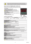
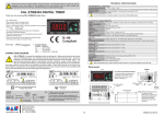
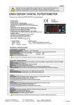
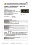
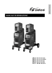
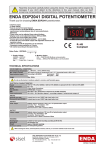
Read this document carefully before using this device. The guarantee will be expired by damaging of the
device if you don't attend to the directions in the user manual. Also we don't accept any compensations for
personal injury, material damage or capital disadvantages.
CAL ET2011 PID TEMPERATURE CONTROLLER
Thank you for choosing CAL ET2011 temperature controller.
* 77 x 35mm sized.
* Selectable dual setpoint.
* Selectable thermocouple types or PT100 input. (Specify at order).
* Automatic calculation of PID parameters. (SELFTUNE).
°F
C/A2
A1
SSR
Selftune for automatic PID calculation or
manually enter PID parameters if known.
°C
F
SET
* Soft-Start feature.
* Zero point input shift.
* C/A2 Relay output programmable as alarm or control output.
* Selectable SSR control output.
* Selectable heating/cooling control.
* In the case of sensor failure, manual control can be selected.
* CE marked according to European Norms.
CAL
ET2011
TECHNICAL SPECIFICATIONS
Input type
°C
PT100 Resistance thermometer
PT100 Resistance thermometer
J (Fe-CuNi) Thermocouple
K (NiCr-Ni) Thermocouple
T (Cu-CuNi) Thermocouple
S (Pt10Rh-Pt) Thermocouple
R (Pt13Rh-Pt) Thermocouple
EN 60751
EN 60751
EN 60584
EN 60584
EN 60584
EN 60584
EN 60584
Temperature range
°F
-99.9...300.0 °C
-99.9...543.0 °F
-200...600 °C
0... 600 °C
0...1300°C
0... 400°C
0...1700°C
0...1700°C
-328...1112 °F
+32... +1112 °F
+32... +2372 °F
+32... +752 °F
+32... +3092 °F
+32... +3092 °F
Accuracy
0,5% (of full scale)
0,5% (of full scale)
0,5% (of full scale)
0,5% (of full scale)
0,5% (of full scale)
0,5% (of full scale)
0,5% (of full scale)
1 digit
1 digit
1 digit
1 digit
1 digit
1 digit
1 digit
ENVIRONMENTAL CONDITIONS
Ambient/storage temperature 0 ... +50°C/-25... +70°C (with no icing)
80% Relative humidity for temperatures up to 31°C, decreasing linearly to 50% at 40°C.
Max. Relative humidity
According to EN 60529
Front panel : IP65
Rated pollution degree
Rear panel : IP20
Max. 2000m
Height
Do not use the device in locations subject to corrosive and flammable gases.
ELECTRICAL CHARACTERISTICS
230V AC +%10 -%20, 50/60Hz or 24V AC %10, 50/60Hz
Max. 5VA
Power connector: 2.5mm²' screw-terminal, Signal connector: 1,5mm² screw-terminal conenction.
Max. 100ohm
EEPROM (minimum 10 years)
EN 61326-1: 2006
EN 61010-1: 2010 (Pollution degree 2, overvoltage category II)
Supply
Power consumption
Wiring
Line resistance
Data retention
EMC
Safety requirements
OUTPUTS
C/A2 output
SSR output
Life expectancy for relay
Relay : 250V AC, 8A (for resistive load), Selectable as NO+NC Control or Alarm2 output.
Relay : 250V AC, 16A (for resistive load), Selectable as NO Control or Alarm2 output.
Max 20mA 12Volt (as control output)
Without load 30.000.000 mechanical operation; 250V AC, on the 8A resistive load
100.000 electrical switching
CONTROL
Control type
Control algorithm
A/D converter
Sampling time
Proportional band
Control period
Hysteresis
Output power
Single set-point and alarm control
12 bit
100ms
Adjustable between 0% and 100%. If Pb=0%, On-Off control is selected.
Adjustable between 1 and 250 seconds
Adjustable between 1 and 50°C/F
The ratio of power at a set point can be adjusted between 0% and 100%
HOUSING
Housing type
Dimensions
Weight
Enclosure material
Suitable for flush-panel mounting according to DIN 43 700.
W77xH35xD71mm
Approx. 200g (after packing)
Self extinguishing plastics.
While cleaning the device, solvents (thinner, benzine, acid etc.) or corrosive materials must not be used.
www.west-cs.com
|
WEST Control Solutions
The Hyde Business Park
Brighton East Sussex
BN2 4JU United Kingdom
Tel : +44 (0) 1273 606271
Fax : +44 (0) 1273 609990
ET2011-E-01-CAL-2014-01
1/4
Entering from the programming mode to the run mode:
If no key is pressed within 20 seconds during programming mode, the data is stored automatically and the run mode is entered.
SET
SET
If
key is pressed while holding
SET
SET
key, the programming mode is enabled.
Alternatively, the same function occurs first pressing
together,data is recorded and running mode is entered.
key and
F
key is pressing programming mode is entered.Then
and
keys are pressing
Programming mode
SET
SET
SET
AL2.o.
Con.o.
SET
SET
S.tun.
ConF.
SEcu.
If co.SE parameter is different
from C-A2,this parameter is seen.
C.s.Lo.
C.s.lo.= Control set point lower limit.(for
selected output)
Adjustable between 0 and C.s.Hi.
A2.S.L
a2.s.l= Alarm2 set value lower limit.
Adjustable between 0 and A2.S.H
parameter value.
C.s.Hi.
C.s.Hi.= Control setpoint upper limit.(for
selected output)
Adjustable between C.s.Lo. and Upper scale
value.
A2.S.H
a2.s.H= Alarm2 set value upper limit.
Adjustable between A2.S.L
parameter value and upper scale
value.
C. Pb = Proportional band.(for selected
output)
Adjustable between %0.0 and %100.0.
C. Pb= %0.0,On-Off control is selected.
A2.HY
a2.Hy= Hysteresis of the Alarm2
output.
Adjustable between 1 and 50 °C.
A2.tP
A2.tp = Function of Alarm2 type.
Four kinds of functions can be
selected.
indE.= Independdnt alarm
(Independent)
dE. = Deviation
bAnd = Band alarm (Band)
bAn.i = Band with inhibition
C. pb
C.Hys
C. ti
C. td
C. Ct.
C.Hys = Hysteresis of the output.(for
selected output)
Adjustable between 1 and 50 °C.
C. Pb= 0,this parameter is active.
C. ti = Integral time.(for selected output)
Adjustable between 0 and 100.0 minutes.
C. ti = 0.0,integral impact is disable.
C. Pb parameter is different from “0”,this
parameter appears.
C. td = Derivative time.(for selected output)
Asjustable between 0.00 and 25.00 minutes.
C. td = 0.0, derivative time is disabled.
C. Pb parameter is different from”0”,this
parameter appears.
A2.Er.
C. Ct. = Period time.(for selected output)
Adjustable between 1 and 250 second.
C. Pb parameter is different is different
from“0”,this parameter appears.
C.p.st
C.p.st = The ratio of output power at the
setpoint.Adjustable between %0 and %100.
C.E.p.s.
C.E.P.s. = The percentage of faulty sensor
selected output power.Adjustable between
%0 and %100.
s.s.t.s.
A2.St.
inp.t.
inp.t. = Input type selection.
FE.cn.= J type ,nc.nA.= K type c.cn.= T
type p10.r.=S type , P13.r.= R type
thermocouple selection.
This parameter varies when changing
some parameters.
s.t.Co.
St.Cu =SETSelf tune control parameter.
If both
keys are pressed ,yes
message is displayed on the screen
and selftune process is started
automatically.
SET
Unit
fltr.
fLtr.= Coefficient of digital filter.
Filter for display value.
Adjustable between 1 and 200. If this parameter is 1,
digital filter runs most quick. If the parameter is 200,
the filter run most slow. The value of parameter should
be increased in interference.
offs.
A2.st. = The state of Alarm2 output.
Hi= If A2 output is above the set
value. (on)
lo= If A2 output is above the set
value.(off)
C.o.sE = Control output selection
C-A2= C/A2 (Relay) output selection
SSR = SSR output selection
oFfS. = Offset value.
Offset value is added to the measurement value.
Adjusted between -100 and +100°C.The normal value is 0.
F.k.E.C.
F.kE.C. = Function key setting parameter
nonE= Function key is off.
C2.S.A.= The function key with 2.set value is used.
manu. = Manual mode can be achieved with the
function key.
dSP.o.= Only the temperature display mode is
entered with function key.
m.SEt.
m.SEt. = The percentage of manual output parameter.
Adjustable between %0 and %100.
This parameter allows manual adjustment of the output
power when the manual output selection.
C. Pb.= 0, this parameter is not seen.
A2.Er. = State of Alarm2 output in the
case of sensor failure.
on= A2 output is probe failure (on).
off= A2 output is probe faiure (off).
S.Cod = Security menu access
code.
It should be 2011.
Co.sc.
Cosc. = Parameters of CoN.o.
menu security access level code.
nonE = Invisible.
P.yEs = Modification can be done.
P. no = Only visible.
a.2.sc. = Parameters of al2.o.
menu security access level code.
nonE = Invisible.
P.yEs = Modification can be done.
P. no = Only visible.
If both
keys are pressed, no
message is displayed on the screen
and selftune process is stopped.
Unit = The temperature unit.
°C= °C,°F= °F
(This parameter varies when
changing some parameters.)
C.o.sE
S.Cod.
When the self tune begins, PIdt. message
and measurement value are shown
alternately.
After the completion of the self tune process,
st.Co. parameter is automatically changed to
no and the device returns to working mode.
If the measured temperature is higher than
90% of the set value at the beginning of the
self tune process, then tE.Hi. message is
shown alternately and the measured
temperature is waited to go below %60 of
the set value. After that, self tune operation
is started automatically.
If it is intended to abort the self tune
process, St.Co. parameter is changed to
no and
key is pressed.
Sst.S =Sofy starter timer set value
This parameter indicates the time to reach set point
value when the device is first energised.
Adjustable between 0 and 250 minutes.
If 0 is selected, soft start feature will be enable and the
device reaches set point value quickly.
Setting Pb = 0, soft start feature will be disabled.
a.2.sc.
Cn.sc.
Co.sc. = Parameters of Conf.
menu security access level code.
nonE = Invisible.
P.yEs = Modification can be done.
P. no = Only visible.
S.t.sc.
S.t.Sc. = Parameters of S.tun.
menu security access level code.
nonE = Invisible.
P.yEs = Modification can be done.
dEF.P.
Co.sc. = Parameters of Conf.
menu security access level code.
no = Parameter settings are not
change.
yEs = Parameter setting will be
restored.
Modification Of Parameter Diagram
SET
SET
6
Chys
SET
5
6
DEFAULT PARAMETERS
C.typ
C.typ. = Control output type
C.typ. = HEAt means heating control.
C.typ. = CooL means cooling control.
Control output
parameters
Set parameters
Alarm2 output
parameters
TC input PT100 input
TC input PT100 input
C1.sE. 400
C2.SE. 400
A2.SE. 500
While the parameter names appear,if
and F
keys are pressed together, returns to the program mode.
C.s.lO.
C.s.Hi.
C. PB
C.HyS
C. ti
C. td
C. Ct.
C.P.St.
C.EP.S.
S.s.t.S.
C.typ.
0
-200
600
0
2
4.0
1.00
20
0
0
0
HEat
A2.s.l
A2.s.H
A2Hy.
A2.tp
a2.st.
a2.Er.
0
-200
600
2
indE
Hi
on
Configuration
parameters
Pt.
inp.t. FE.cn.
Unit
°C
25
Fltr.
C.o.SE.
C-A2
0
offs.
f.k.E.C.
nonE
50
m.sEt.
Security
parameters
Self tune
parameters
TC input PT100 input
TC input PT100 input
a2.Er.
no
When holding
P.yEs
P.yEs
P.yEs
P.yEs
no
key, the value of parameter flashes and using
keys the requested value can be adjusted.
TC input PT100 input
Co.sc.
A2.Sc.
Cn.Sc.
S.t.Sc.
dEf.P.
SET
If
key is pressed and held 0.6 seconds, the value of the selected
parameter changes rapidly. If waited enough,the value increases 100 at each
step. After 1 second following the release of the key, initial condition is
returned.The same procedure is valid for the decrement key.
2/4
ET2011-E-01-CAL-201401
TERMS
(5)
°F
C/A2
A1
( 1 ) Measurement value and set value indicator Running mode)
Parameter name and value (Programming mode)
( 2 ) Value increment key (Programming mode)
If only this key is pressed in normal operation,software version
number is seen. (F.k.E.C. parameter processing)
SSR
°C
F
SET
CAL
( 2) Value decrement and parameter selection key.
(Programming mode)
ET2011
( 4 ) Control ve Alarm set selection key (Running mode)
Parameter set key (Programming mode)
( 1 ) PV and SV display
Character heights
( 2 ),( 3 ),( 4 ) Keypad
( 5 ) State indicator
7 segment, 4 digits red LED display
12 mm
Micro switch
For control, Alarm1 and SSR outputs 3 digits red LED
ALARM2 OUTPUT TYPES
Independent Alarm
A2.tp.=indE
SV
ON
Band Alarm
A2.tp.= bAnd
Deviation Alarm
A2.tp= dE.
SV
SV
ON
ON
OFF
OFF A2.St.= Hi
ON
ON
ON
OFF
OFF A1.St.= Lo
OFF
OFF
A2.Hy
a2,Hy
A2.Hy
SV+ASV +300
(ASV min. = beginning of scale-300
ASV max. = end of scale)
(ASV min. =-300, ASV max. = +300)
A2.St.= Hi
A2.Hy
SV-ASV
ASV
A2.St.= lo
SV+ASV
300
300
SV =Set point of CONT output
ASV = Set point of AL2 output
(ASV min. = 0, ASV max. = +300)
SV
= Set point of CONT output
ASV = Set point of alarm output
Band Alarm With Inhibit
A2.tp.= bAn.i
SV+ASV
SV+ASV
SV
SV
SV-ASV
SV-ASV
ON
OFF
ON
OFF
Beginning
Band alarm is possible
SV =Set point of CONT output
Beginning
Band alarm is possible
ASV = Set point of AL2 output (ASV min. = 0, ASV max. = 300 )
MODIFICATION OF CONTROL AND ALARM SET POINTS
ERROR MESSAGES
250
3 seconds later
pfa
SET
C1.SE.
399
400
3 seconds later
Sensor is broken
----
Temperature value is
higher than the value
____
Temperature value is
lower than the scale
psC
PT100 sensor is short circuit
C2.SE.
399
398
3 seconds later
F.kE.C. parameter, is set to the C2.S.A. parameter,this
parameter is displayed.
a2.SE.
499
500
3 seconds later
C.O.SE.parameter is set to the output of SSR,this
parameter is seen.
SET
3/4
ET2011-E-01-CAL-201401
DIMENSIONS
Depth
73mm
77mm
°F
C/A2
A1
SSR
F
35mm
°C
5mm
For removing mounting clamps ;
- Push flush mounting clamps in
direction 1 as shown in the figure below.
Then pull out the clamps in direction 2 .
SET
CAL
ET2011
Connection
cable
2
2
3
2
6
5
4
10
9
8
7
11 12
+
29,5mm
C/A2 - 250V AC 8A
RESISTIVE LOAD
230V AC +10% -20%
50/60Hz 5VA
1
ET2011-T-230VAC
PID DIGITAL THERMOSTAT
-
SSR OUT
TC
Made In Turkey
1
Panel cut-out
71,5mm
+
-
Flush mounting Panel
clamp
Flush mounting
clamp
1
Flush mounting
clamp
2
8 680407 711246
CAL Controls | www.west-cs.com SN: XXXXXXXXX
Note :
1) Panel thickness should be maximum 7mm.
2) If there is no 60mm free space at back side of the
device, it would be difficult to remove it from the panel.
Order Code : ET2011-
-
-
1- Input selection
RT....PT100 input
T....TC input
3
2
1
3- Contact current selection
2 - Supply Voltage
None......8A contact output
230VAC...230V AC
P....16A contact output
110VAC....110V AC
024VAC......24V AC
SM...........9-30V DC / 7-24V AC
CONNECTION DIAGRAM
CAL ET2011 is intended for installation within control panels. Make sure that the device is used only for intended
purpose. The shielding must be grounded on the instrument side. During an installation, all of the cables that are
connected to the device must be free of electrical power. The device must be protected against inadmissible humidity,
vibrations, severe soiling. Make sure that the operation temperature is not exceeded. All input and output lines that are
not connected to the supply network must be laid out as shielded and twisted cables. These cables should not be close
to the power cables or components. The installation and electrical connections must be carried out by a qualified staff
and must be according to the relevant locally applicable regulations.
CAL Controls | www.west-cs.com SN: XXXXXXXXX
C/A2 - 250V AC 8A
RESISTIVE LOAD
-
4
5
6
7
8
9
10
C/A2 - 250V AC 8A
RESISTIVE LOAD
1
11 12
CAL Controls | www.west-cs.com SN: XXXXXXXXX
C/A2 - 250V AC 16A
RESISTIVE LOAD
184-253V AC 5
50/60Hz 5VA 6
www.west-cs.com
|
4
5
6
7
8
PT100
9
10
11 12
CAL Controls | www.west-cs.com SN: XXXXXXXXX
6
7
8
8 680407 720156
Made In Turkey
TC
+
NOTE :
SUPPLY:
3
5
9
10
110V AC +10% -20%
50/60Hz 5VA
C/A2 - 250V AC 16A
RESISTIVE LOAD
+
+
Holding screw
0.4-0.5Nm
2
4
8 680407 720071
110V AC +10% -20%
50/60Hz 5VA
1
3
Made In Turkey
ET2011-RT-110VAC-P
PID DIGITAL THERMOSTAT
SSR OUT
ET2011-T-110VAC-P
PID DIGITAL THERMOSTAT
2
1
11 12
2
3
4
5
6
7
8
SSR OUT
3
110V AC +10% -20%
50/60Hz 5VA
TC
+
2
8 680407 720118
Made In Turkey
+
+
1
CAL Controls | www.west-cs.com SN: XXXXXXXXX
ET2011-RT-110VAC
PID DIGITAL THERMOSTAT
SSR OUT
8 680407 720033
110V AC +10% -20%
50/60Hz 5VA
SSR OUT
ET2011-T-110VAC
PID DIGITAL THERMOSTAT
Made In Turkey
PT100
9
10
11 12
Equipment is protected throughout
by DOUBLE INSULATION.
Note 1) Mains supply cords shall meet the requirements
of IEC 60227 or IEC 60245.
Switch
2) In accordance with the safety regulations, the
Phase
230V AC
power supply switch shall bring the identification of
Neutral
Supply
the relevant instrument and it should be easily
Fuse should
accessible by the operator.
Cable
size:
1,5mm²
be connected.
Fuse
F 100 mA
250V AC
WEST Control Solutions
The Hyde Business Park
Brighton East Sussex
BN2 4JU United Kingdom
Tel : +44 (0) 1273 606271
Fax : +44 (0) 1273 609990
4/4
ET2011-E-01-CAL-201401