1
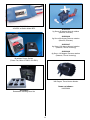
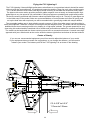
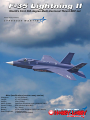
F-35 Lightning II
World's First 360-degree Multi-Vectored Thrust EDF Jet
Product officially licensed by
Main Specifications (receiver ready version)
Wingspan:
31-1/2" [800mm]
Length:
47-1/4" [1200mm]
Weight:
35oz [1000g]
Motor System:Outrunner brushless motor (B2839/2750Kv
Speed Control:
45A w/Switch Mode BEC
Servos:
9g, (10pcs)
Battery:4-Cell 14.8V 2200mah 20C Li-poly battery
Radio Required:7-channel radio
(2.4GHz recommended)
Table of Contents
Product Introduction
The F-35 is the first foam jet model that uses
360-degree vectored thrust control. Through
controlling the direction of the thrust nozzle, you will
be able to imitate all kinds of thrilling maneuvers that
are possible in the Full-Scale F-35 Lightning II.
Product Introduction..................................................2
Before Beginning Assembly......................................2
Parts Included in Kit (receiver ready version)............2
Read Before Flight (general safety guidelines) ........3
Safety Instructions for Charging and
Using Li-Poly Batteries ........................................3
Safety Precautions....................................................3
General Safety Statements.......................................3
Battery Precautions...................................................4
Mixing Epoxy.............................................................4
Wing Install................................................................4
Stabilizer Install.........................................................5
Rudder Install............................................................6
Nose cone Install.......................................................6
Receiver and Battery Install......................................7
Linkage Install...........................................................7
Programming Your Radio System.............................8
Replacing or Inspecting the Ducted Fan Unit............11
Setting the Control Throws........................................11
Replacement Parts....................................................11
Flying the F-35 Lightning II........................................15
Center of Gravity.......................................................15
Before Beginning Assembly
This model is designed for assembly and operation
by experienced modelers. Make sure you read
through the illustrated instructions before beginning
the assembly process. Please contact Hobby Lobby
if you have any questions regarding the assembly
or operation of your model, to discuss any potential
problem areas of assembly, or the possibility of
returning the unassembled model if you feel you
cannot complete it as described in this manual.
Parts Included in Kit (receiver ready version)
•
•
•
•
•
•
•
Fuselage (painted and decorated)
Rudder
Retractable landing gear set
70mm Ducted fan (installed)
Brushless 45A ESC (installed)
Canopy
Two-part 5-minute epoxy
•
•
•
•
•
•
•
2
Main wing set (painted and decorated)
Elevator
4-Cell Li-poly Battery 20C
Outrunner Brushless motor (installed)
360-degree Vectored Thrust Nozzle (installed)
Decals (applied)
Instructions
Read Before Flight (general safety guidelines)
Safety Precautions
1. Before each flight, please check the aircraft
using the radio system. Check the operation of
all control surfaces and the motors to make sure
they are operating properly and that none of the
clevises or connectors are damaged.
2. This aircraft is not a toy! Its operation is quite
different from RC cars and RC boats. Before
flying, please read the user manual carefully and
obey the regulation in order to enjoy a safe and
pleasant flight.
3. Before flying your model, make sure there are no
other pilots using the same frequency within 1.2
miles of your model if flying using a 72MHz radio
system. Please refrain from flying until you have
discussed who flies when so your plane does not
become damaged from stray radio signals.
4. If you find any parts included with this model
that are defective, contact Hobby Lobby before
starting assembly.
1. Please do not change any part of the plane
without checking with Hobby Lobby. You will be
responsible for any damages caused by these
changes.
2. Your flying area should be wide-open and free
of obstacles. Never fly near highways, railways,
airports, power lines or in residential areas.
3. To avoid personal injury, never fly your model
near or facing people, or throw the plane in their
direction.
4. Do not fly your model in strong winds or severe
weather.
5. Do not allow loose objects, tools or body parts to
get near the intake of your model. Items can be
pulled in and can damage the model or cause
personal injury.
6. Never dispose of batteries or parts of your model
in a fire as it could lead to an explosion and
personal injury.
Safety Instructions for Charging and
Using Li-Poly Batteries
•
•
•
•
•
•
•
•
•
General Safety Statements
1. This aircraft is not a toy. It has been designed
for the experienced modeler and pilot. You are
responsible not to cause damage to other’s
personal property or cause personal injury.
2. Please follow the instructions provided to build,
adjust and operate your model. Use caution not to
get hands, hair or other body parts near the fans.
Doing so could cause personal injury.
3. Hobby Lobby and our dealers are not responsible
for any economic or law liability for any improper
usage or operation of this model.
4. This model is designed for use by modelers age
14 and over. This model is not recommended for
unsupervised modelers under 16 years of age.
5. Never use the model or associated electronics in
damp or rainy conditions.
6. This model is made from EPS and Polystyrene,
which can be damaged by excessive heat. Keep
you model away from excessive heat or out of
direct sunlight for extended time periods or it can
become warped and affect the flight performance
of the model.
7. Never attempt to catch your model while in flight.
8. Never leave the battery connected while the
model is unattended. Accidental operation can
occur and cause personal injury.
9. Before operating the model, make sure to turn on
the radio system and check the functions before
beginning flight.
10. Always make sure the throttle at the transmitter
has been moved to the low or off position before
connecting the motor battery.
Do not put the battery on, or near anything, that
can catch fire when charging.
Always charge the battery on a non-flammable
base i.e. a metal tray.
Do not disassemble the battery.
Do not short-circuit the battery.
Do not use, or leave, the battery nearby a fire,
stove or heated place.
Do not immerse the battery in water or seawater,
do not get it wet.
Do not charge the battery near a fire or under the
blazing sunlight.
Do not drive a nail into the battery, strike it with
hammer or apply excessive weight to the battery.
Do not impact or throw the battery.
3
Battery Precautions
•
•
•
•
•
•
•
•
•
•
•
•
•
•
•
•
•
•
•
•
•
•
Mixing Epoxy
Do not use the battery if it is damaged or
deformed.
Do not solder the motor leads directly to the
battery.
Do not reverse charge or over discharge the
battery.
Do not reverse charge or connect the battery in
reverse to the speed control.
Do not connect the battery to the ordinary charger
socket or car cigarette jack.
Do not use the battery for unspecified equipment.
Do not touch the leaking battery directly. Wash
your skin or clothes with water if they come in
contact with a damaged battery.
Do not mix the Li-Po battery with other unchargeable battery.
Do not continue charging the battery over the
prescribed time.
Do not put the battery into a microwave oven or
high-pressure container.
Do not use an abnormal or damaged battery.
Do not use or store a battery under the sunlight.
Do not use the battery near any sources that
generate static electricity (over 64V)
Do not charge the battery when the environmental
temperature is under 32 degrees or over 130
degrees.
If you find the battery leaking smelling or
abnormal, stop using it.
Keep the battery away from children.
Use the specified charger and observe charging
requirement provided by the battery manufacturer.
Parental supervision is required when charging or
operation is done by minors.
Never charge the battery at a rate greater than
specified by the battery manufacturer.
Never discharge the battery at more than 25C and
never take the voltage lower than 12V as this will
damage the battery.
For full flight time it is recommended to cycle the
battery a minimum of three cycles before use in
your model.
Never charge the battery on a carpet floor as this
can cause a fire.
When mixing epoxy, make sure to use equal amounts
of Part A and Part B. Mix the epoxy thoroughly. You
will have about 3 minutes before the epoxy begins to
cure after mixing so work quickly. Do not mix epoxy
until you fully understand the assembly procedure.
Wing Install
Read through the following steps before attaching
the wings to the fuselage. You will need to complete
these steps before the epoxy begins to cure.
Mix some epoxy to glue the wings to the fuselage.
Apply a thin layer of epoxy to the wing root and
fuselage to glue the wings to the fuselage.
4
Stabilizer Install
Plug the aileron servo into the lead
coming from the fuselage.
Read through the following steps before attaching the
hinges and elevators to the fuselage. You will need to
complete these steps before the epoxy begins to cure.
Before installing the hinges, it is recommended to
apply a small amount of light oil to the hinge point
of all four hinges. This will help prevent the epoxy
from entering the hinge point which could glue the
hinge, preventing it from operating correctly.
Mix a small amount of epoxy. Apply epoxy into
the T-shaped hinge pocket in the fuselage
for the hinge. Also apply epoxy to the hinge
pocket for the adjoining elevator.
Position the hinge half into the T-shaped pocking in
the fuselage. Use a small flat screwdriver to press the
hinge fully into the pocket. The elevator can now be
positioned on the hinge to complete the assembly.
Attach the wing panels one at a time. Make sure
each panel is tight to the side of the fuselage and
the upper surface of the wing is flush with the
adjoining fuselage surface. Allow the epoxy to fully
cure before continuing the assembly of your model.
5
Repeat the procedure to attach the second
elevator half to the fuselage using two hinges.
Allow the epoxy to fully cure before continuing
with the assembly of your model.
Press the rudder firmly into the fuselage.
Install both rudders at this time. Allow
the epoxy to fully cure before continuing
with the assembly of your model.
Rudder Install
Nose cone Install
Gluing the rudders follows the same procedure
as gluing the wings. Make sure to align each
part equally on each side of the fuselage.
Use epoxy to glue the nose cone to the fuselage.
Make sure the nose cone fits tight on the fuselage.
6
Make sure the pitot tube on the nose
cone is aligned with the center line of the
fuselage before the epoxy cures.
Close the battery door. Turn the latches
1/4-turn to secure the door closed.
Linkage Install
Receiver and Battery Install
Before installing the linkages to the control
surfaces and vectored nozzles you will need
to center the servos. Use the sub-trim feature
of your radio system to center each servo.
Locate the leads for the servos. Each lead is
marked with its function. Plug the leads into the
appropriate ports of the receiver. The elevator
thrust vectoring plugs into the AUX2 location
and the rudder thrust vectoring plugs into
AUX1. Place the receiver in the fuselage.
Adjust the length of the elevator and aileron
linkages. When the servo is centered the control
surfaces must be centered at the same time.
Place the battery in the fuselage. Don't forget to
connect the battery lead to the speed control lead
before closing the battery door. Always make sure to
have the transmitter on when connecting the battery to
avoid the receiver from picking up stray radio signals.
7
Programming Your Radio System
Align the stabilizer so it is 7/16" (10.5mm to 11mm)
below the edge of the fuselage as shown.
The following describes the mixing necessary
to operate the thrust vectoring of your
model. Use this information to program your
radio to operate the thrust vectoring.
From the INPUT SELECT screen,
inhibit AUX2 and FLAP.
From the WING TYPE screen, make sure
that all the selections are set to OFF.
Adjust the linkages to the thrust nozzle so it is
aligned as shown in the drawing. The reference
lines are molded into the thrust nozzle assembly.
From the D/R & EXPO screen, select the AILE
function. Set the dual rate switch for the ailerons to
the "0" position. Set the EXPO for +30% to make
the ailerons less response around the stick center.
B
A
8
From the D/R & EXPO screen, select the AILE
function. Set the dual rate switch for the ailerons to
the "1" position. Set the EXPO for +30% to make
the ailerons less response around the stick center.
Set the D/R to 60% for the low rate for the ailerons.
From the D/R & EXPO screen, select the RUDD
function. Set the dual rate switch for the rudder to
the "0" position. Set the EXPO for +30% to make
the steering less response around the stick center.
From the D/R & EXPO screen, select the RUDD
function. Set the dual rate switch for the rudder to
the "1" position. Set the EXPO for +30% to make the
steering less response around the stick center. Set
the D/R to 60% for the low rate for the steering.
From the D/R & EXPO screen, select the ELEV
function. Set the dual rate switch for the elevator to
the "0" position. Set the EXPO for +30% to make
the elevator less response around the stick center.
From the D/R & EXPO screen, select the ELEV
function. Set the dual rate switch for the elevator to
the "1" position. Set the EXPO for +30% to make
the elevator less response around the stick center.
Set the D/R to 60% for the low rate for the elevator.
The image below shows the positions for the servo
reversing. Select REVERSING SW from the radio
menu and set channels 2, 3 and 5 to reverse (REV).
All other channels will be in the NORM position.
9
Select PROG.MIX1 from the radio menu. Set
the mix for ELEV to AUX2. Make sure the rates
are both at +100%, and that the switch is set to
MIX. There should be no offset for this mix.
Thrust nozzle shown with left thrust mixing activated.
Thrust nozzle shown with up thrust mixing activated.
Select PROG.MIX2 from the radio menu. Set the
mix for RUDD to FLAP. Make sure the rates are set
at +120% and 85% as shown, and that the switch is
set to MIX. There should be no offset for this mix.
Thrust nozzle shown with down
thrust mixing activated.
Thrust nozzle shown with right thrust mixing activated.
10
Replacing or Inspecting the Ducted Fan Unit.
Setting the Control Throws
Use the following to set the high and low rate throws
for the ailerons and elevators. If you have used our
mixing suggestions, the throws for the thrust vectoring
will be correct once the control surface throws are set.
Low Rates: General flying without thrust vectoring
Elevator 1/2" up and down
Ailerons 1/2" up and down
High Rates: Thrust vector flying
Elevator 1" up and down
Ailerons 3/4" up and down
These are the rates that we use when flying the F-35
and are a good starting point. You may find that you
prefer to change these to suit your flying style.
Replacement Parts
HLI350002
Elevators and Rudders
HLI350003
Wings
11
HLI350004
Fuselage and Nose Cone
HLI350007
Decals
HLI350010
Brushless Motor 2750Kv
HLI350008
Canopy and Nose Cone
HLI350011
4S Lipoly Battery 2200mAh (Genuine
Deans Ultra Conns)
HLI350009
70mm Ducted Fan Unit
12
HLI350012
45A ESC w/Switch Mode BEC
HLI350015
9g Servo 90 degree Normal rotation
(Ailerons, Elevator)
HLI350016
9g Servo 90 degree Reverse rotation
(Ailerons, Elevator)
HLI350017
9g Servo 120 degree Normal rotation
(Retracts, Thrust Vectoring)
HLI350018
9g Servo 120 degree Reverse rotation
(Retracts, Thrust Vectoring)
HLI350013
Brushless Power System
(70mm Fan, Motor 2750Kv, 45A ESC)
HLI350019
360 Degree Thrust Vector Nozzle
Items not shown:
HLI350006
HLI350014
Retractable Landing Gear Set
13
Flying the F-35 Lightning II
The F-35 Lightning II has solid flight performance when flown as a conventional electric ducted fan model
(without using the vectored thrust). It is quick and responsive and the 70mm fan on 4 cells provides nearly
1 to 1 thrust. When the multi-vector 360 degree thrust vectoring is activated the excitement really starts.
The side-to-side vector action provides powerful rudder response even at nearly no forward speed. High
alpha flight at very low speed is fully controllable. Falling leaf spins are possible both upright and inverted.
The thrust vectoring combined with elevator makes impossible flips easy to do. The key to great flights are
in the initial setup of the model, follow our recommendations on control throws and center of gravity and
set up the dual rates with expo and you will be rewarded with a great flying model with unique abilities.
The retractable landing gear is best suited to smooth runways. If flying from taller grass, hand launching is
easily accomplished. There are a couple of techniques that are helpful to learn. The model can be successfully
landed with the thrust vectoring turned on by landing in a “high alpha” attitude. The ground speed will be very
slow using this method and the combined use of throttle and vectored thrust makes for a smooth soft landing.
The model can be landed with the thrust vectoring turned off in a conventional manner. A smooth nose high
approach with just a little throttle at the end to arrest the decent right before touchdown is the best method.
Center of Gravity
If you use our recommended equipment you will not need to adjust the balance of your model.
If your equipment does not match our suggestions, or you change the airframe, you will need to
balance your model. The balance point of the F-35 Lightning II is as shown in the drawing.
CG: 4-5/8" to 4-3/4"
117mm to 120mm
14
Use this page to take notes on building, programming your radio and flying your
Lockheed Martin F-35 Lightning II.
15
Have Fun!
We hope that you have many pleasant flights with your
Lockheed Martin F-35 Lightning II.
Hobby Lobby International
5614 Franklin Pike Circle
Brentwood, TN 37027
www.hobby-lobby.com
0005