1
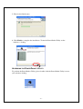
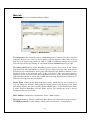
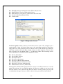
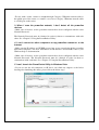
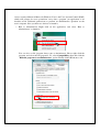
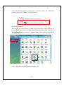
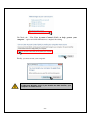
HomePlug 85Mbps 4
ports Ethernet Switch
User’s Guide
Revision 1.0
Table of Contents
Chapter 1: Introduction ................................................................................ 1
Chapter 2: Planning your PowerLine Network............................................. 2
Network Topology .................................................................................... 2
Chapter 3: Getting to Know the PowerLine Switch ......................................... 2
The Top Panel........................................................................................... 2
The Front Panel......................................................................................... 2
Chapter 4: Connecting the PowerLine Ethernet Switch.......................................... 3
Connecting the Switch .............................................................................. 3
Connecting to a Router.............................................................................. 5
Chapter 5: Using the PowerPacket Utility.................................................... 5
Utility Installation ..................................................................................... 5
Accessing the PowerPacket Utility............................................................ 7
Main tab ................................................................................................. 8
Privacy tab ........................................................................................... 10
Diagnostics Tab.................................................................................... 11
About Tab ............................................................................................ 13
Appendix A: Troubleshooting.................................................................... 13
Common Problems and Solutions ........................................................... 13
Frequently Asked Questions ................................................................... 18
Appendix B: Specifications........................................................................ 19
How to Use this User Guide
The user guide to the HomePlug 85Mbps 4 ports Ethernet Switch has been designed to
make understanding networking with the PowerLine Ethernet Switch easier than ever.
Look for the following items when reading this User Guide:
This checkmark means there is a note of interest and is something
you should pay special attention to while using the PowerLine
Ethernet Switch
This exclamation point means there is a caution or warning and is
something that could damage your property or the PowerLine
Ethernet Switch.
Chapter 1: Introduction
Welcome
Thank you for choosing the PowerLine Ethernet Switch. The Switch will allow you to
network better than ever. How does the Switch do all of this? The PowerLine Ethernet
Switch lets you turn the existing powerlines in your home or office into a high-speed
network. Now you don’t have to drill through the walls, and climb through the attic or
cellar to install network cables, just use the wires that already run through the building.
The Switch provides convenient powerline access to office/family users by sharing a
simple AC power line network. Embedded HomePlug 1.0 Turbo (85Mbps) interface
enables you to connect 4 PC Ethernet ports to another PC’s at other end of power line,
and not limited by the wall or layer that block RF wireless communication.
But what does all of this mean?
Networks are useful tools for sharing computer resources. You can access one printer
from different computers and access data located on another computer's hard drive.
Networks are even used for playing multiplayer video games. So, networks are not only
useful in homes and offices, they can also be fun.
The PowerLine Ethernet Switch follows the HomePlug network standard. Just connect
the PowerLine Ethernet Switch into the wall, and connect your Ethernet-equipped device
to the Switch using the included network cable, and you’ve turned your whole house into
a network infrastructure. Attach more computers to the network by simply connecting
them into the wall anywhere in the house, using more PowerLine Ethernet Bridge or
Switch.
Once your computers are connected to the network, they can share resources like printers
and storage space, and all kinds of files: music, digital pictures, and documents. With up
to 85Mbps data rates, you can play head-to-head network computer games, too. And if
you use a PowerLine Ethernet Switch to interface Broadband Routers from your cable or
DSL Internet connection to your powerline network, you’ll be able to get to the Internet
from any computer in the house.
Use the instructions in this Guide to help you connect the Switch, set it up, and configure
it to bridge your different networks. These instructions should be all you need to get the
most out of the Switch.
-1-
Chapter 2: Planning your PowerLine Network
NETWORK TOPOLOGY
With the powerline products, a network can be
created using home powerlines. Computers can be
networked over powerlines using powerline devices.
The Switch connects an Ethernet-enabled computer
to a powerline network. The powerline USB
Adapter is also available for connecting a USBenabled computer to a powerline network.
The Switch is also ideal for any user who already
has a router and wants to share high-speed internet access across the powerline network.
Connect the Switch to the router after you have configured the Switch using the
PowerPacket Utility. Because our Ethernet ports of Switch have auto-MDIX function,
you can just connect a Category 5 Ethernet network cable to the uplink port of the router,
or connect a Category 5 Ethernet network cable to a LAN port on the router.
Chapter 3: Getting
Getting to Know the PowerLine Switch
THE TOP PANEL
The Switch’s 4 Ethernet Ports, where these Ethernet Ports are connected and located on
the front panel.
The Ethernet Ports are where you will
connect the included Category 5
Ethernet network cable.
THE FRONT PANEL
The Switch’s LEDs, where information about network activity are to be displayed, are
located on the front panel.
-2-
LABEL
Power
STATUS
On
Off
On
PLC
Blinking
Off
1, 2, 3, 4
LAN
On
Blinking
Off
DESCRIPTION
Power on.
Power off
Product detects another PLC
device
Powerline activity
Product didn't detect any
PLC device
Ethernet port link
Ethernet activity
No Ethernet port link
PLC :Power Line Communication
Chapter 4: Connecting the PowerLine Ethernet
Switch
CONNECTING THE SWITCH
1. Plug the included Category 5 Ethernet network cable into the computer’s Ethernet port.
2. Plug the other end of the cable into the Ethernet port of the Switch.
-3-
3. Plug the electrical cable into electrical port.
Plug the other end of this electrical cable into a wall electrical outlet.
IMPORTANT: Because the Switch sends data over the power lines of
your house, connect the Switch directly into an electrical outlet. It’s
recommended not to connect the device into a power strip with surge
protection. And do not connect the device into UPS. The Switch has its
own power filter for protection against surges.
The installation of the Switch is complete. If you want to configure the Switch, proceed to
“Chapter 5: Using the PowerPacket Utility.”
-4-
CONNECTING TO A ROUTER
If you want to share high-speed Internet access across a powerline network, then you can
choose to connect the Switch to a router.
Follow these instructions:
Disconnect the network cable from the PC, and connect it to the router. The installation
of the Switch is complete.
Chapter 5: Using the PowerPacket
PowerPacket Utility
OVERVIEW
After installing the Switch, you will run the Setup Wizard to install the PowerPacket
Utility. Use this utility to check the connection status of the powerline network, search
for powerline devices on your network, and set up security using a network password.
Note: If you want the devices on your powerline network to share highspeed internet access, connect the Switch to a router after you run the
PowerPacket Utility. Refer to “ Chapter 4: Connecting the PowerLine
Ethernet Switch.”
UTILITY INSTALLATION
、
、
Utility can be installed in Windows98 Windows Me Windows 2000
NT Windows XP Windows 2003 Server Windows Vista
、
、
、
、Windows
1. Insert the included utility CD into the CD-ROM drive, and then to launch the
setup.exe program from the setup folder.
-5-
2. Click Next to continue.
3. Enter your information and click Next.
.
4. The system will automatically search for the destination location, just click Next to
continue.
-6-
5. Wait for the finish status.
6. Click Finish to complete the installation. To run the PowerPacket Utility on the
windows‘s desktop.
ACCESSING THE POWERPACKET UTILITY
To perform the PowerPacket Utility, please double-click the PowerPacket Utility icon on
your windows desktop.
-7-
Main tab
Shows the main screen of the PowerPacket Utility.
Figure 1: Main Screen
The top panel of the screen shot shows a HomePlug device connected locally to the host
computer. In most cases, only one device will be seen. In situations where there are more
than one local device being connected, such as a USB or an Ethernet adapter, the user can
select the local device by clicking on it and then click the Connect button to its right.
The lower panel displays all the HomePlug remote devices, discovered on the current
logical network. The total number of remote devices connected on the same network can
be found on top of the Remote device panel. The Network type (Public or Private) is also
displayed based on the network status of the local device. The scan status option is
displayed on the top right corner above the Remote devices panel showing whether the
Autoscan functionality is turned ON or OFF. The following information is displayed for
all devices that appear in the lower panel.
Device Name column shows the default device name, which may be user re-defined. A
user can change the name by either using the rename button or by clicking on the name
and editing in-place. An icon is usually shown with the name. A color distinction in icons
is made between HomePlug 1.0 and Turbo devices. By default, the icon is always
accompanied by a device name.
MAC Address column shows the Remote device’s MAC address.
Password column by default is blank and ‘Enter Password’ button can be used to enter it.
The DEK password is on the adapter’s label, please refer from it, see the Figure 2..
-8-
PL65000001
00B0520B025C
XK8Y-GH26-BR1K-LZSA
Figure 2: Password on the label
To enter the Password of the device (required when creating a private network), first
select the device by clicking on its name in the lower panel and then click on the Enter
Password button. A dialog box will appear as shown in Figure 3 to type the password.
The selected device name is shown above the password field and the password can be
verified by hitting the OK button. The Password field accepts the Device password in any
case formats, with or without dashed between them.
A confirmation box will appear if the password was entered correctly. If a device was not
found, the user will be notified along with the suggestions to resolve common problems.
This process might take a few seconds to get completed.
Figure 3: Set Device Password
The Add button is used to add a remote device to the existing network by entering the
device password of the device. A dialog box will appear as shown below in Figure 4. The
dialog box allows the user to enter both a device name and the password.
-9-
A confirmation box will appear if the password was entered correctly and if the device
was found in the powerline network. If a device was not found, the user will be notified
and suggestions to resolve common problems will be presented.
Figure 4: Add Remote Device.
The Scan button is used to perform an immediate search of the HomePlug devices
connected to the Powerline network. By default, the utility automatically scans every few
seconds and updates the display screen.
Quality, show the quality between two device.
Rate, show the current transmission rate of selected device.
MAC address, show the device’s MAC address.
The picture is shown in Figure 1.
Privacy tab
The Privacy screen provides the user with an option to maintain security for their logical
network and also to select the devices that has to be included in the network. The
appearance is shown in Figure 5.
All HomePlug devices are shipped using a default logical network (network name),
which is normally “HomePlug”. The Privacy dialog screen allows user to change to a
private network by changing the network name (network password) of devices.
The user can always reset to the HomePlug network (Public) by entering “HomePlug” as
the network name or by clicking on the Use Default button.
- 10 -
Figure 5: Privacy Screen.
The Set Local Device Only button can be used to change the network name (network
password) of the local device. If a new network password is entered, all the devices seen
on the Main panel prior to this will be no longer present in the new network, effectively
making the local devices not to communicate to the devices who were in the old logical
network. Devices previously set up with the same logical network (same network name)
will appear in the device list afterward selecting this option.
The Set All Devices button is used to change the logical network of all devices that
appear on the Main panel whose Device’s Password had been entered for the same
logical network. A dialog window will appear to report the success of this operation. For
devices whose device password’s were not entered, this operation will fail and will report
a failure message.
Diagnostics Tab
The Diagnostics screen shows System information and a history of all remote devices
seen over a period of time. The appearance is shown in Figure 6. This screen is available
for OEM/ODM Customization.
The Upper panel shows technical data concerning software and hardware present on the
host computer which were used to communicate over HomePlug on the Powerline
network. It shall include the following:
Operating System Platform/Version
Host Network Name
User Name
MAC Address of all NICs (Network interface card) connected to the host
Identify versions of all Driver DLLs and Libraries used (NDIS) and optionally
- 11 -
HomePlug chipset manufacturer name (Turbo Only devices)
MAC Firmware Version (Turbo Only devices)
MAC addresses of all devices connected locally to the host
Version of the PowerPacket Utility
Vendor name
Figure 6: Diagnostics Screen
.
The Lower panel contains a history of all remote devices seen on the computer over a
certain period of time. All devices that were on the powerline network are listed here
along with a few other parameters. Devices that are active on the current logical network
will show a transfer rate in the Rate column; devices on other networks, or devices that
may no longer exist are shown with a “?” in the Rate column. The following remote
device information is available from the diagnostics screen:
Device Alias Name
Device MAC Address
Device Password
Device Last known rate
Device Last Known Network name
HomePlug chipset manufacturer name
Date device last seen on the network
MAC Firmware Version. (Turbo Only)
The diagnostics information displayed may be saved to a text file for later use, or can be
printed for reference for a technical support call. Devices, which are not part of the
network anymore, can be deleted using the delete button. A dialog window pops up with
a confirmation message if we try to delete a device whose password has been entered.
- 12 -
About Tab
The About screen shows the software version and released Date.
Figure 7: About dialog screen
Preferences
The lower part of the panel may display options for user customizations or preferences
(such as turning the auto-scan feature on or off) as shown Figure 7 above.
Appendix A: Troubleshooting
This appendix consists of two parts: “Common Problems and Solutions” and
“Frequently Asked Questions.” This appendix provides solutions to problems that may
occur during the installation and operation of this product. Read the description below to
solve your problems.
COMMON PROBLEMS AND SOLUTIONS
1. None of the LEDs light up after I installed the Switch.
• Unplug the Category 5 Ethernet network cable from the computer. Unplug the Switch
from the electrical outlet. Then repeat the hardware installation process. Make sure the
electrical outlet is working properly.
2. The Ethernet LED does not light up on the Switch.
• When the Ethernet port detects a LAN connection, the Ethernet LED will light up.
Check the Ethernet adapter on your computer to see if the connection and adapter are
working properly. Make sure you are using the included Category 5 Ethernet network
cable (which is straight-through) to connect the Switch to your computer. Do not use a
crossover cable.
- 13 -
For use with a router, connect a straight-through, Category 5 Ethernet network cable to
the uplink port of the router, or connect a crossover, Category 5 Ethernet network cable
to a LAN port on the router.
•
3. When I scan the powerline network, I don’t detect all the powerline
devices.
• Make sure all devices on the powerline network have been configured with the same
Network Password.
The Network Password must be identical in order for them to communicate with each
other. See “Chapter 5: Using the PowerPacket Utility.”
4. I can’t connect to other computers on my powerline network or to the
Internet.
• Make sure the IP address and TCP/IP protocol are set up correctly for all the powerline
networked computers. For more information on IP addresses and TCP/IP, refer to your
Windows help or documentation.
• Make sure all devices on the powerline network have been configured with the same
Network Password. The Network Password must be identical in order for them to
communicate with each other. See “Chapter 5: Using the PowerPacket Utility.”
5. I can’t launch the PowerPacket Utility in Windows Vista.
• If you are sure the all connection is OK, but it can’t find any adapters as the below
drawing after launching this utility, please follow the below steps.
- 14 -
A new security addition in Microsoft Windows Vista is the User Account Control (UAC)
which will prompt for user's permission every time a program (an application or an
installer) needs additional permissions to perform an administrative operation on the
user's computer. Now you have two choices to launch it.
1.
Run as Administrator. Right click on the application, and select “Run as
Administrator” to launch it.
You can also set the program always run as administrator. Please right click the
program, and select the file properties. To select Compatibility sheet and click the
“Run this program as an administrator” option. Finally click OK button to exit.
- 15 -
After you run this program as administrator, it still also prompt you to allow the
program. Please click “Allow” to start the program.
2. Disable UAC function.
The program can’t successfully to launch is due to the UAC security function. So
you can disable the function to launch it. Please follow the below steps to disable it.
Go to Control Panel and change to “Classic View”. Then double click the “User
Accounts” item.
Click “ Turn User Account Control on or off ” item.
- 16 -
Un-Check the “ Use User Account Control (UAC) to help protect your
computer ” option and click OK button to complete the setting.
Finally, you must restart your computer.
IMPORTANT: Because the UAC function is the new security addition
in Microsoft Windows Vista. If you disable the UAC function, your
computer are under the risk.
- 17 -
FREQUENTLY ASKED QUESTIONS
1. How to distinguish the Turbo adapter from 14 Mbps adapter?
Go to the Network Connections of Control Panel. And open the Connection which one is
connecting and also finish the hardware installation. You can check the connection speed
is 100.0 Mbps, but 14M will show 10.0Mbps.
Turbo type
14M type
2. Do the Instant powerline products cause interference with other home
networking or powerline products?
No. The Instant powerline products can co-exist with phone line and wireless networking
technologies. Instant powerline operates in a different frequency band than powerline
control and can co-exist with technologies such as X-10, CEBus, and LONworks.
3. How do the Instant powerline products handle signal interference
between two adjacent homes? How is eavesdropping prevented?
To ensure network separation between homes, the Instant powerline products use 56-bit
DES security encryption, which is enabled by default. To encrypt data, this encryption
method uses the Network Password you set using the PowerPacket Utility.
- 18 -
Appendix B: Specifications
Standards
Ports
Cabling Type
Data Rate
LEDs
Security Features
Dimensions
Certifications
Operating Temp.
IEEE 802.3, IEEE 802.3u, HomePlug 1.0 Turbo(85Mbps) ,
HomePlug 1.0 (14Mbps)
Four 10/100 Auto-Sensing , Auto crossover RJ-45 Ports
UTP CAT 5 or better
Up to 85 Mbps
Power, PLC, 1 ~ 4 LAN
56-bit Data Encryption with Key Management,
Network Password to secure local powerline networking
(W x D x L):121.4 mm x 100 mm x 28.5 mm
FCC Part 15, Part B, Class B, CE Class B,
UL (option), CB (option), ICE Class B (option),
cUL (option), CB/VDE (option)
0ºC ~ 40ºC (32ºF ~ 104ºF)
Storage Temp.
-20ºC ~ 70ºC (-4ºF ~ 158ºF)
Operating Humidity
10% ~ 90% Non-Condensing
Power input
Storage Humidity
QoS
100 ~ 240 V / 50 ~ 60 Hz
5% ~ 95% Non-Condensing
4 priority queues
- 19 -