1
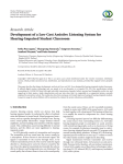
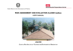
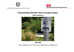
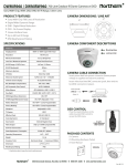
PSI Union Co.,Ltd :
1/908 Moo17 Kukot, Lamlukka , Pathumthani 12130 Thailand
Tel : +66 80 459 0567 Hotline : +66 84 932 5405 Email : [email protected]
AVE100 Series
Circuit Tester
User Manual
1
Picture 1 : Front Panel
1. Mode Selection
1.1 Mode SETUP : Use for engineering set up.
1.2 Mode RUN : Use for production run.
** Select switch RUN/SETUP on Front panel and push RESET for enter
selection mode.
1.1
Mode SETUP:Use for engineering set up.(7Modeinside)
01: Test Data (3 mode inside)
A) Lasted Result : view the lasted data.
B) View Test Data : view the summary data. (Test, unit, pass, fail,
%yield)
C) Clear Test Data : Clear all data. (Test, unit, pass, fail, %yield)
02: Run Setup (7 mode inside)
A) View Step Header : View the detail of step file.
B) View Step Data : View pin number and hi-lo limit .
C) Test Result : 5 Mode inside
1. Display Summary : Choose the product / step result or none at
display show.
2. Product Display : Choose product display type > pass / fail / all /
selected unit or none at display show.
3. Select Product : Add new select or clear all for product.
2
4. Step Display : Choose step display type > pass / fail / all /
selected unit or none at display show.
5. Select Step : Add new select or clear all for step.
D) PC-Link (Select 3 mode for connect with computer)
1. Disable : Not sent the data.
2. Result Only : Sent data pass / fail only.
3. M-Value&Result : Sent data value and pass / fail.
E) U-Plate Action (Select 2 mode for floating the upper plate)
1. Test Finish : Upper plate floating when test finish.
2. All Step Pass : Upper plate floating when all step pass.
F)
Clear Offset : Use for start new machine, found error etc.
Password : 0000 (for inicial)
G)
Debug Mode : Enable or disable
03: Fixture Setup (3 mode inside)
A) Output Control : Manual output control. (on/off 8 Port-Main,
8 Port-EXT1, 8 Port-EXT2)
B) Source Control : Choose the voltage source (3.3V / 5V).
C) U-Plate Control : View the status for upper plate.
04: Default Setting : For setting the Factory default .
05: Info : View the machine information.
06: Support : View the contact person for machine service.
07: Update Firmware : For update new version of machine
firmware.
3
1.2
Mode RUN : Use for production run.
** This mode is automatic run, display is according to setup
parameter from setup mode.**
2. PC Program : AVE100 Data Collector
2.1
Use for collecting the data (pass / fail / value / process time).
2.2
Barcode, 2D Code Scanner available.
2.3
Connect with PC by USB Cable.
2.4
Database system supported.
Picture 2 : AVE100 Data Collector Program
4
3. Instruction
3.1
Front Panel.
- PASS/FAIL LED : For Show testing status.
- BUZZER button : For On/Off buzzer alarm.
- RESET button : For reset all status.
- RUN/SETUP switch : For Select mode.
- Direction button : For Control direction.
Picture 1 : Front Panel
3.2
Back Panel.
- 220VAC Plug : For Connect with power cable.
- POWER button : For On/Off power.
- USB PORT : For data collection connect with PC.
- PGM PORT : For update new firmware
- TEST PORT : For Connect with Fixture/Product.
- OUTPUT PORT : For control electronic device.
Picture 3 : Back Panel
5
3.3
Dimension.
- Width 29 cm.
- Length 28 cm.
- High 10 cm.
Picture 4 : AVE100 Circuit Tester
4. Optional
** AVE100E Extension Module : Function depend on customer
requirement.
Picture 5 : AVE100E Extension Module
6