1
PDF created with FinePrint pdfFactory trial version http://www.pdffactory.com
CopyRight 2002-2004© V2.0
This manual may not be reproduced in whole or in part by mimeogyaph
or any other means, without permission of Amptron.
The information contained in this document is believed to be accurate at
the time of publication, however, Amptron assumes no responsibility for any
errors which may appear here and reserves the right to make changes without
notice. Please ask the local represent for latest product specications before
ordering.
Ⅰ
PDF created with FinePrint pdfFactory trial version http://www.pdffactory.com
Please read this manual carefuly before doing installation,
operation and mantenance of Ai205.
,
Following symbols are used in this user s manual and on meter
to alert the dangerous or to prompt in the operating or setting
process.
Dangerous symbol, Failure to observe the information may result in injury or death.
Alert symbol, Alert the potential dangerous.
Observ the information after the symbol to avoid possible injury or death.
Installation and maintenance of the Ai205 meter should only be
performed by qualified, competent personnel that have appropriate
training and experience with high voltage and current device.
Ⅱ
PDF created with FinePrint pdfFactory trial version http://www.pdffactory.com
Content
Copyright…………………………………………………………………………………………………Ⅰ
Notice………………………………………………………………………………………………………Ⅱ
Start…………………………………………………………………………………………………………Ⅲ
Content……………………………………………………………………………………………………Ⅳ
Chapter 1 Introduction………………………………………………………………………………1
The Purpose of Ai205……………………………………………………………………2
The Application Area of Ai205…………………………………………………………4
The Function of Ai205……………………………………………………………………4
Ai205 Series………………………………………………………………………………5
Chapter 2 Installation………………………………………………………………………………7
Appearance and Dimensions………………………………………………………………8
Installation Method…………………………………………………………………………9
Wiring of Ai205……………………………………………………………………………12
Chapter 3 Basic Operation and Setup……………………………………………………………29
Display Panel and Keys……………………………………………………………………30
Metering Data Reading………………………………………………………………………32
Statistics Display……………………………………………………………………………41
Meter Parameter Setting……………………………………………………………………44
Introduction of Measurement and Functions of Ai205………………………………52
Chapter 4 Communication…………………………………………………………………………61
Introducing Modbus Protocol………………………………………………………………62
Format of the Communication……………………………………………………………65
Address Table of Ai205…………………………………………………………………71
Appendix…………………………………………………………………………………………………93
Appendix A Technical Data and Specification…………………………………………94
Appendix B Ordering………………………………………………………………………97
Ⅲ
PDF created with FinePrint pdfFactory trial version http://www.pdffactory.com
Starting!
Congratulations!
You have got an advanced, Versitil, multifunction power meter. You may call
it a Remote terminal unit(RTU). It will benifit your power system.
When you open the package, you will find the following items.
1.Ai205 meter
1
2.14Pin terminal
1 (another for option)
3.Installation clips
4
,
4.User s operation mannual
1
Please read this manual carefuly before operating or setting the Ai205 meter
to avoid unnecessary trouble.
You may read part of this manual depend on how you use the Ai205 meter.
Chapter 1 helps you to understand the fundamental function, specification
and application area of Ai205.
Chapter 2 describes in detail the installation and wiring of Ai205.
Chapter 3 tells you the data display and paramenter setting method of Ai205.
Chapter 4 gives the communiaction address table of Ai205.
Appendix lists the technical data and specifications of Ai205 and ordering
information.
Ⅳ
PDF created with FinePrint pdfFactory trial version http://www.pdffactory.com
Chapter 1 Introduction
The purpose of Ai205
The Application Area of Ai205
The Function of Ai205
Ai205 Series
1
PDF created with FinePrint pdfFactory trial version http://www.pdffactory.com
The Purpose of Ai205
Powerful Intelligent Power Meter
Ai205 Series Intelligent power meter was designed by used of latest
microprocessor and digital signal process technology. Electric power parameters,
energy and demands metering, power quality monitoring, remote control, over
range alarming, statistics and records, all these functions are only in one pocketsize unit. There are also alarm on over/under Voltage, Current,Power, Power
Factor, Frequency, Unbalance Factors or Demands and Pulse Output based on
Energy or Reactive Energy in Ai205. Switch status monitoring is possible by
using the 4 digit inputs. It combines high accuracy measurement with intelligent
multifunction and simple HMI interface.
Idea Choice for Electric Automation SCADA System
Ai205 can be used to replace all traditional electric meters. It also can be
used as Remote Terminal Unit (RTU) for monitoring and controlling in a SCADA
system. All the measured data is available via digital RS485 communication ports
running the MobusTM protocol.
Energy Management
Ai205 can measure double directions four quadrants Kwh and Kvarh with
accuracy up to 0.5%. It can provide high standard energy data and energy demand
data. All these data is important for statistics of each line feeder and total.
2
Remote Power Control
The main function of Ai205 is measurement, but it has also got some flexible
I/O functions. This made the meter can be used as distributed RTU (metering,
monitoring, remote controlling in one unit).
PDF created with FinePrint pdfFactory trial version http://www.pdffactory.com
Power Quality Analysis
With the powerful digital signal processing ability the Ai205 intelligent power
meter can be used as an online power quality analysis instrument. It can
simultaneously and continuously give out the analysis results such as THD of
voltage and current, harmonics up to 31st and unbalance factor of voltage and
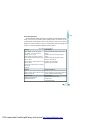
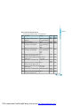
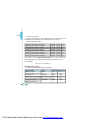
current, etc. The main function of Ai205 are listed in table1.1
Table 1.1 Main function of Ai205 series
Metering
Phase Voltage: V1, V2, V3, Vlnavg
Power Quality
THD, Even THD and Odd THD of phase/line
Line Voltage: V12, V23,V31,Vllavg
Current: I1, I2, I3, Iavg, In
Voltage
Harmonics and Crest factor of phase/line
Power: Power of each phase and total
Reactive Power: Reactive Power of each
Voltage
THD, Even THD and Odd THD of Current
phase and total
Harmonics and K Factor
Unbalance Factor of Voltage
Apparent Power: Apparent Power of each
phase and total
Unbalance Factor of Current
Power Factor: Power factor of each phase
and average
Frequency
Statistics
Energy and Demand
Maximum value of statistics with time stamp Kwh of 4 quadrants: Import, Export, Total, Net
Mininum value of statistics with time stamp Kvarh of 4 quadrants: Import, Export, Total, Net
Demand of Power and Reactive Power
Maximum of Demand
Communication
RS485 Communication port
Modbus RTU Protocol
Remote Control
4 Digital Input (DI) (Wet or Dry)
2 Relay Output
2 Digital Output (DO)
3
PDF created with FinePrint pdfFactory trial version http://www.pdffactory.com
The Application Area of Ai205
Power Distribution Automation
Industry Automation
Energy Manage System
Intelligent Electric Switch Gear
Building Automation
Large UPS System
The Function of Ai205
Multifunction, High Accuracy
Ai205 Series Intelligent power meter was designed by use of latest
microprocessor and digital signal processing technology. Electric power
parameters metering, energy and demand recording, power quality monitoring,
remote controlling, over range alarming, statistics and records, all these functions
are only in one pocket-size unit. There are also basic alarm on over/under
Current, Voltage, Power, Power Factor, Frequency, Unbalance Factors or
Demands and Pulse Output based on Energy or Reactive Energy in Ai205. Status
monitoring is possible using the 4 digital inputs. It combines high accuracy
measurement with intelligent multifunction and friendly HMI interface.
Accuracy of Voltage and Current is 0.2%
Accuracy of Power and Energy is 0.5%
Small Size and Easy Installation
With the size of DIN96 × 96 and 55mm depth after mounting, the Ai205 can
be installed in a small cabin. The clips are used for easy installation and remove.
Easy to Use
By using of large screen high density LCD, the display of Ai205 is easy to
read and use. All the setting parameters can be access by using panel keys or
communication port. The setting parameters are protected in EEprom, which will
maintain its content after the meter is power off. With the backlight of the LCD,
4
PDF created with FinePrint pdfFactory trial version http://www.pdffactory.com
the display can be easily read in the dim environment. The back light “on” time is
selectable.
Multiple Wiring Modes
In either high voltage or low voltage or three phase three wire or three phase
four wire or single phase system, the Ai205 can be easily used.
Ai205 series
The Ai205 series have two kinds of product, the standard Ai205 and the
advanced Ai205. Both these two products have multiple choice of I/O. Advanced
Ai205 has the basic measuring function of Ai205. It also gets extra function as
harmonics analysis, Max/Min record and over/under limit alarming.
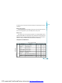
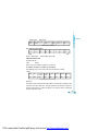
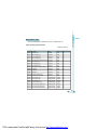
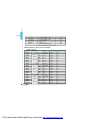
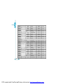
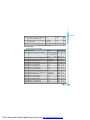
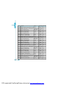
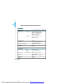
Comparison of Ai205 Series
Table 1.2 Comparison of Ai205
Parameter
METERING
ENERGY&
REAL TIME MEASURING
DEMAND
FUNCTION
P0
P1
P2
P3
Phase Voltage
V1,V2,V3,Vlnavg
√
√
√
√
Line Voltage
V12,V23,V31,Vllavg
√
√
√
√
Current
I1,I2,I3,In,Iavg
√
√
√
√
Power
P1,P2,P3,Psum
√
√
√
√
Reactive Power
Q1,Q2,Q3,Qsum
√
√
√
√
Apparent Power
S1,S2,S3,Ssum
√
√
√
√
Power Factor
PF1,PF2,PF3,PF
√
√
√
√
Frequency
Frequency
√
√
√
√
Energy
Ep_imp,Ep_exp,Ep_total,Ep_net
√
√
√
√
Reactive Energy Eq_imp,Eq_exp,Eq_total,Eq_net
√
√
√
√
√
√
√
√
Demand
Dmd_P,Dmd_Q,Dmd_S
5
PDF created with FinePrint pdfFactory trial version http://www.pdffactory.com
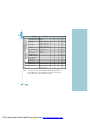
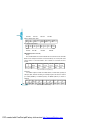
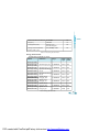
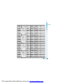
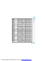
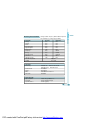
POWER QUALITY
P0
P1
P2
P3
√
√
√
√
Current Unbalance Factor I_unbl
√
√
√
√
Voltage THD
√
√
√
√
√
√
√
√
Parameter
THD_V1,THD_V2,
THD_V3,THD_Vavg
Current THD
THD_I1, THD_I2,
THD_I3, THD_Iavg
STATISTICS
MONITORING
FUNCTION
Voltage Unbalance Factor U_unbl
Harmonics
Harmonics 2 nd to 31 st
√
√
Voltage Crest Factor
Crest Factor
√
√
TIF
THFF
√
√
Current K factor
K Factor
√
√
MAX with Time Stamp
√
√
MIN with Time Stamp
√
√
√
√
Switch Status(DI)
OTHERS
I/O
√
√
Relay Output
√
Pulse Output
√
ALARM Over/Under Limit Alarm
COMM RS485 Port
ModbusTM Protocol
√
TIME Real Time Clock
Year,Month,date,Hour,
√
√
√
√
√
√
√
√
√
minute,Second
Note:
1. There are two DIs in the basic Module of Ai205. The Option module can
provide additional 2 DIs, DI Auxilary Power, 2 DOs and 2 Relay Outputs.
2. The 2 DOs may be used as Alarm or Pulse output.
6
PDF created with FinePrint pdfFactory trial version http://www.pdffactory.com
√
Chapter 2 Installation
Appearance and Dimensions
Installation method
Wiring of Ai205
7
PDF created with FinePrint pdfFactory trial version http://www.pdffactory.com
The installation method is introduced in this chapter. Please read this chapter
carefully before beginning installation work.
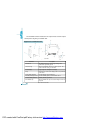
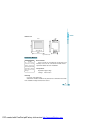
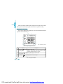
Appearance and Dimensions
⑥
③
⑦
②
①
①
⑧
⑤
④
Figure2.1 Appearance of Ai205
1. Enclosure
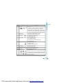
Part Name
Description
The Ai205 enclosure is made of high strength anti-
2. Front Casing
combustion engineering plastic
After the installation, this part is in front of panel. The
3. LCD Display
4. Key
5. Input Wiring Terminal
6. Auxiliary Wiring Terminal
7. Extend Wiring Terminal
8. Installation Clip
color of the front casing is selectable.
Large bright blue backlight LCD Display
Four keys are used to select display and to set parameters
of the meter
Used for Voltage and Current input
Used for auxiliary power, communication and DI
Auxiliary I/O wiring terminals
When installation the clips are used for fixing the meter to
the panel
8
Table2.1 Part name of Ai205
PDF created with FinePrint pdfFactory trial version http://www.pdffactory.com
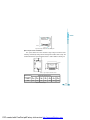
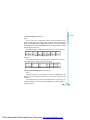
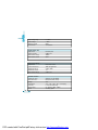
Dimensions
Front
Side
43.00
00.06
00.96
38.50
55.00
96.00
Fig.2.2 Dimensions
Installation Method
• Note
The installation
environment should
fulfill the temperature
and humidity that Ai205
meter requires. Otherwise
it may cause the meter
damaged.
Environmental
Please check the environment temperature and
humidity to ensure the satisfaction of Ai205 meter’s
requirement before the meter installation.
Temperature
Operation: -20oC to 70oC
Storage: -40oC to 85oC
Humidity
5% to 95% non-condensing
Ai205 meter should be installed in dry and dust free environment and avoid
heat, radiation and high electrical noise source.
9
PDF created with FinePrint pdfFactory trial version http://www.pdffactory.com
+ 0.5
9 0-
0.0
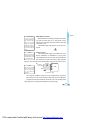
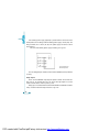
Installation Steps
Normally, Ai205 was installed on the panel of switch gear.
1. Cut a square hole on the panel of the switch gear.
The cutting size is as fig.2.3
Unit (mm)
Cut
9 0+0.5
- 0.0
Panel
Fig.2.3 Panel Cutting
2. Remove the clips from the meter and insert the meter into the square hole
from the front side.
Panel
Fig.2.4 Put the meter into the square hole
3. Put clips back to the meter from the backside and push the clip tightly so
that the meter is fixed on the panel.
10
PDF created with FinePrint pdfFactory trial version http://www.pdffactory.com
Panel
Fig.2.5 Use the clips to fasten the meter on the panel
a
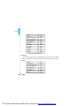
Space required for Installation
The space around the meter should be large enough so that the meter
removing, terminal strip wiring and wire arrangement could be done easily. The
recommend minimum space around the meter is show in Table2.2 and Fig.2.6.
c
d
Panel
g
f
b
e
Panel
Environment
Temperature
< 50℃
≥ 50℃
a
25
38
b
25
38
Fig 2.6 Space around the meter
Minimum Distance(mm)
c
d
e
38
38
64
51
51
76
f
25
38
g
25
38
Table 2.2 Minimum Space
PDF created with FinePrint pdfFactory trial version http://www.pdffactory.com
11
Wiring of Ai205
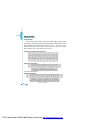
Terminal Strips
There are three terminal strips on the back of Ai205, Voltage & Current Input
Terminal Strip, Auxiliary Terminal Strip and Extend Terminal Strip. Only the Ai205
with PRIO option has the Extend Terminal Strip. The 1, 2 and 3 are used to
represent each phase of three phase system. They have the same meaning
with A, B and C or R, S and T in three phase system.
Voltage & Current Input Terminal Strip
Auxiliary Terminal Strip
Aux.
Note: NC means No Connection
Extend Terminal Strip
12
Fig 2.7 Terminal Strips
PDF created with FinePrint pdfFactory trial version http://www.pdffactory.com
DANGEROUS
Only the qualified
personnel could do the
wire connection work.
Make sure the power
supply is cut off and all
the wires are electroless.
Failure to observe it may
result in severe injury or
death.
Safety Earth Connection
Before doing the meter wiring connection, please make
sure that the switch gear has a safety Earth system.
Connect the meter safety earth terminal to the switch gear
safety earth system.
The following safety earth symbol is used in the user’s
manual.
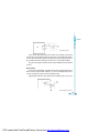
Auxiliary Power
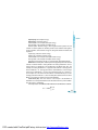
The auxiliary power supply of the Ai205 meter is 85264Vac (50/60Hz) or 100-300Vdc. Typical power
consumption of the meter is less than 2W. A regulator or a
UPS should be used when the power supply undulates
too much. The terminals for the auxiliary power supply are 20, 22 and 24 (L, N,
G).
1A FUSE
• Note
Make sure the voltage of
power supply is the same
as what the meter needed
for its auxiliary power.
• Note
Make sure the auxiliary
power terminal of the
meter G is connected to
the safety Earth of
switchgear.
85~264Vac
Power Supply
Ground
20 L
22 N
Ai205
24 G
Fig 2.8 Power supply
A fuse (typical 1A/250Vac) should be used in auxiliary power supply loop.
No. 24 terminal must be connected to the safety earth system of switchgear.
An isolated transformer or EMI filter should be used in the auxiliary power
supply loop if there is power quality problem in the power supply.
13
PDF created with FinePrint pdfFactory trial version http://www.pdffactory.com
• Note
A filter should be used
if there is EMI problem
1A FUSE
85~264Vac
Power Supply
L
N
Ground
G
Power
filter
L
20 L
N
22 N
G
24 G
Ai205
Fig.2.9 Wiring of Auxiliary Power supply under EMI
The choice of wire of power supply could be AWG16-22 or 0.6-1.5mm 2
Voltage Input
Two Voltage Input options of Ai205 are 100Vac and 400Vac.
100Vac option is suitable for low voltage system that less than 120Vac or
high or medium voltage system that the secondary of PT is 100Vac. The input
voltage V1, V2 and V3 against Vn of Ai205 should be less than 120Vac if the
100Vac option is selected.
400Vac option is suitable for low voltage system that less than 480Vac. The
voltage input could be directly connected to the terminal of Ai205 without the use
of PT. The input voltage V1, V2 and V3 against Vn of Ai205 should be less than
480Vac. If the input voltage is higher than 480Vac, the PT should be used.
A fuse (typical 1A/250Vac) should be used in voltage
• Note
input loop.
The secondary of PT
PT should be used to transform the high voltage into
can not be shorted,
otherwise it may cause
measurement range of Ai205 if it is used in high voltage system.
the severe damage of
The wire number of voltage input could be AWG16-22
the instrument.
or 0.6-1.5mm2
Note:In no circumstance could the secondary of PT be shorted. The secondary of PT should
be well grounded.
14
PDF created with FinePrint pdfFactory trial version http://www.pdffactory.com
Current Input
In a practical engineering application, CTs should be installed in the loop of
measuring. Normally the secondary of CT is 5A. 1A is possible in the ordering
option. A CT of accuracy over 0.5% (rating over 3VA) is recommended and it will
influence the measuring accuracy. The wire between CT and Ai205 should be
as shorter as possible. The length of the wire may increase the error of the
measurement.
The wire number of current input could be AWG15-16 or 1.5-2.5mm2
The CT loop should not be open circuit in any circumstance when
the power is on. There should not be any fuse or switch in the CT loop
and one end of the CT loop should be connected to the ground.
Vn Connection
Vn is the reference point of Ai205 voltage input. The lower is wire resistance
the less is the error.
Three phase wiring diagram
Ai205 can satisfy almost all kinds of three phase wiring diagram. Please read
this part carefully before you begin to do the wiring so that you may chose a
wiring diagram suitable for your power system.
The voltage and current input wiring mode can be set separately in the meter
parameter setting process. The voltage wiring mode could be 3 phase 4 line Wye
mode (3LN), 3 phase 4 line 2PT Wye mode (2LN) and 3 phase 3 line open Delta
mode (2LL). The current input wiring mode could be 3CT, 2CT and 1CT. Any
voltage mode could be group with one of the current mode.
15
PDF created with FinePrint pdfFactory trial version http://www.pdffactory.com
Voltage Input Wiring
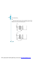
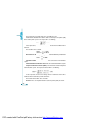
3-Phase 4-Line Wye mode (3LN)
The 3-Phase 4-Line Wye mode is popularly used in low voltage electric
distribution power system. The power line can be connected to the meter voltage
input directly as in fig 2.10. In the high voltage input system, 3PT Wye mode is
often used as in fig 2.11. The voltage input mode of the Ai205 should be set 3LN
for both voltage input wiring mode.
Fig 2.10 direct connection
Fig 2.11 3LN with 3PTs
16
PDF created with FinePrint pdfFactory trial version http://www.pdffactory.com
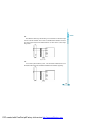
3-Phase 4-Line 2PT mode (2LN)
In some 3-Phase 4-Line Wye system, 2PT Wye mode is often used as in fig 2.
12. It is supposed that the 3 phases of power system are balance. The voltage of
V2 is calculated according to the V1 and V3. The voltage input mode of the Ai205
should be set 2LN for 2PT voltage input wiring mode.
Fig 2.12 2LN with 2PTs
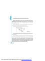
3-Phase 3-Line open Delta Mode (2LL)
Open delta wiring mode is often used in high voltage system. V2 and Vn
connected together in this mode. The voltage input mode of the Ai205 should be
set 2LL for voltage input wiring mode.
Fig 2.13 2LL with 2PTs
PDF created with FinePrint pdfFactory trial version http://www.pdffactory.com
17
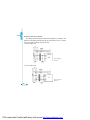
Current Input Wiring
3CT
All the current input of three phase system can be looked as 3CT one, whether
there are 2 CTs or 3 CTs in the input side. The current input mode of the Ai205
should be set 3CT for this current input wiring mode.
Fig 2.14 3CT-a
18
Fig 2.15 3CT-b
PDF created with FinePrint pdfFactory trial version http://www.pdffactory.com
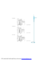
2CT
The difference of the fig.2.16 and the fig.2.15 is that there is not current input
in the I21 and I22 terminals. The I2 value is calculated from formula i1+i2+i3=0.
The current input mode of the Ai205 should be set 2CT for this current input
wiring mode.
Fig 2.16 2CT
1CT
If it is a three phase balance system, 1 CT connection method can be used.
All the other two current are calculated according to the balance supposing.
Fig 2.17 1CT
19
PDF created with FinePrint pdfFactory trial version http://www.pdffactory.com
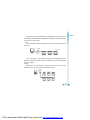
Frequent used wiring method
The voltage and current wiring method are put together in one drawing. The
Ai205 meter will display normally only that the setting of the meter is assorted
with the wiring of the voltage and current input.
1. 3LN, 3CT with 3 CTs
Fig 2.18 3LN,3CT
with 3CTs
2. 3LN, 3CT with 2 CTs
Fig 2.19 3LN, 3CT
with 2 CTs
20
PDF created with FinePrint pdfFactory trial version http://www.pdffactory.com
3. 2LN, 2CT
Fig 2.20 2LN, 2CT
4. 2LN, 1CT
Fig 2.21 2LN, 1CT
5. 2LL, 3CT
Fig 2.22 2LL, 3CT
21
PDF created with FinePrint pdfFactory trial version http://www.pdffactory.com
6. 2LL, 2CT
Fig 2.23 2LL, 2CT
7. 2LL, 1CT
Fig 2.24 2LL, 1CT
8. Single Phase 2 Line (wiring mode setting 3LN, 3CT)
22
Fig 2.25 Single
Phase 2 Lines
PDF created with FinePrint pdfFactory trial version http://www.pdffactory.com
9. Single Phase 3 Line (Wiring mode setting 3LN, 3CT)
Fig 2.26 Single
Phase 3 Line
Wiring of Digital (Switch Statues) Input
There are two digital input of wet contact in standard Ai205. The terminals
of the two Digital input are DI1+, DI1- (15, 16) and DI2+, DI2- (17, 18). Additional
two digital inputs are optional. The terminals of the two additional are DI3+, DI3(25, 26) and DI4+, DI4-(27, 28). The circuit drawing of the digital input is simplified
as Fig. 2.27.
Optical
Isolator
Fig 2.27 Digital Input
Circuit of A
Auxiliary power supply for the digital input is 12-24Vdc. If the connection wire
is too long, a relative higher voltage should be adopted. The current in the loop
line should be less than 10mA-15mA, and the Max current is 30mA.
23
PDF created with FinePrint pdfFactory trial version http://www.pdffactory.com
A DI auxiliary power supply (optional) is provided for the convenient of the
factory field used. The voltage of the DI auxiliary power supply is 15Vdc (1W). The
wiring terminals are V+ and V- (29, 30). This power supply can not be used for
other purpose.
The 4 DIs with auxiliary power supply is drawing as in fig 2.28.
Fig 2.28 Digital Input
with Auxiliary Power
The wire of digital input should be chose between AWG22 (0.5mm2)-AWG16
(1.5mm2).
Relay Output
There are two additional relay output for option in Ai205. The terminal are
R11, R12 (31, 32) and R21, R22 (33, 34). These two relay output are used to
remote control electric switch in power system.
Relay type is mechanical Form A contact with 3A/250V or 3A/30Vdc. A mediate
relay is recommended in the output circuit as in fig. 2.29.
24
PDF created with FinePrint pdfFactory trial version http://www.pdffactory.com
Control
Output
Fig 2.29 Relay output
There are two relay output modes for selection, one is latching, and the other
is momentary. For the latching mode, the relay can be used to output two statues
on or off. For the momentary mode, the output of the relay changes from off to on
for a period of time Ton and than goes off. Ton can be setting from 50-300ms.
The wire of relay output should be chose between AWG22 (0.5mm2)-AWG16
(1.5mm2).
Digital Output
There are two digital outputs for option. The terminals of the digital output are
DO1+, DO1-(35, 36) and DO2+, DO2-(37, 38). These two digital output can be
used as energy pulse output or over limit alarming output.
Digital output circuit form is open collector. The simplified circuit is as fig. 2.30.
Optical
Isolator
Power
Supply
Fig 2.30 Digital output Circuit
25
PDF created with FinePrint pdfFactory trial version http://www.pdffactory.com
The Max working voltage and current are 100V and 50mA.
When the digital output is used as pulse output, DO1 and DO2 can be
programmed as energy pulse output. For example, DO1 is used as energy pulse
output and DO2 is used as reactive energy pulse output. The pulse wide and
pulse constant can be set.
When the digital output is used as over limit alarm output, the up and low limit
of the parameter, time interval and output port can be set.
A drawing of the alarming output with beeper is as fig. 2.31
Power
Supply
Optical
Isolator
Beeper
Fig 2.31 DO
Alarming Circuit
The wire of digital output should be chose between AWG22 (0.5mm2)-AWG16 (1.5mm2).
Communication
The communication port and protocol of Ai205 are RS485 and Modbus-RTU.
The terminals of communication are A, B, and S (11, 12, 13). A is differential
signal +, B is differential signal - and S connected to shield of twisted pair cable.
Up to 32 devices can be connected on a RS485 bus. Use good quality shielded
twisted pair cable, AWG22 (0.5mm2) or larger. The overall length of the RS485
cable connecting all devices can not exceed 1200m (4000ft). Ai205 is used as a
slave device of master like PC, PLC, data collector or RTU.
26
PDF created with FinePrint pdfFactory trial version http://www.pdffactory.com
If the master does not have RS485 communication port, a converter has to be
used. Normally a RS232/RS485 or USB/RS485 is adopted. The topology of RS485
net can be line, circle and star.
1. Line
The connection from master to Ai205 meter is one by one in the RS485 net as
in fig. 2.32.
Resistor
Master
PC
Converter
Fig 2.32 Line mode
In fig. 2.32 the Rt is a anti signal reflecting resistor 120-300 Ohm/0.25W.
Normally, it added to the circuit beside the last Ai205 meter, if the communication
quality is not good.
2. Circle
Ai205 meters are connected in a closed circle for the purpose of high
reliability. There is no need of anti signal reflecting resistor.
232/485
Converter
Master
PC
Fig 2.33 Circle mode
27
PDF created with FinePrint pdfFactory trial version http://www.pdffactory.com
3. Star
The connection of RS485 net is in Wye mode. Anti signal reflecting resistor
may be needed in each line.
232/485
Converter
Master
PC
Fig 2.34 Star mode
The recommendations for the high quality communication,
Good quality shielded twisted pair of cable AWG22 (0.6mm2) or larger is very
important.
The shield of each segment of the RS485 cable must be connected to the
ground at one end only.
Keep cables away as much as possible from sources of electrical noise.
Use RS232/RS485 or USB/RS485 converter with optical isolated output and
surge protection.
28
PDF created with FinePrint pdfFactory trial version http://www.pdffactory.com
Chapter 3 Meter Operation
and Parameter Setting
Display panel and keys
Metering data reading
Statistics display
Meter parameter setting
Introduction of measurement and functions of Ai205
29
PDF created with FinePrint pdfFactory trial version http://www.pdffactory.com
Detail man-machine interface will be discripted in this chapter. This includes
how to get the electric metering data and how to do the parameter setting.
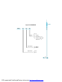
Display panel and keys
There are one display panel and four keys in the front of Ai205. All the display
segments are illustrated in fig 3.1.
13
1
12
3
4
5
2
6
7
11
Fig 3.1 All Display Segments
8
9
SN
1
Display
Discription
Four lines of letter in the Display metering data
metering area
30
10
Voltage, current, power, power factor, frequency, THD,
demand, unbalance factor, max, min etc.
2
One line of letter in the Energy data display or real time clock
energy display area
3
Load rating
Display load current percentage
Table 3.1 Display Panel discription
PDF created with FinePrint pdfFactory trial version http://www.pdffactory.com
SN
4
Display
Discription
Item label
Item label:
Letter
, MAX, MIN,
Demand, PF and F
U: voltage, I: current, P: power, q: reactive power, S:
apparent power, PF: power factor, F: frequency
MAX: Maximum value, MIN: minimum Value, Demand:
Demand value, Avg: average value, I with N: nutrual
5
Three phase
current, PF, F, Avg and N indicate the fourth line data.
With letter U: voltage unbalance factor
6
unbalance label
Load nature
With letter I: Current unbalance factor
Capacitor label: capacitive load
7
Energy label
Inductor: inductive load
imp: consumption energy
exp: generating energy
total: absolute sum of imp and exp energy
8
Communication indicator
net: algebraic sum
No label: no communication
One label: inquiry
Two labels: inquiry and answer
9
Energy pulse
output indicator
No label: no pulse output
With label: pulse output
10
11
Digital input indicator
Time label
Switch 1 to 4 indicate DI1 to DI4
Time display in energy area
12
Unit
Indicate data unit
Voltage: V, KV, Current: A, Power: KW and MW,
Reactive Power: Kvar and Mvar, Apparent Power: KVA
and MVA, Frequency: Hz, Energy: Kwh, Reactive Power:
Kvarh, Percentage: %
31
PDF created with FinePrint pdfFactory trial version http://www.pdffactory.com
There are four delicacy keys labeled as H, P, E and V/A. Use these four keys
to read metering data and do parameter setting.
Metering data reading
Normally, Ai205 display the metering data, such as voltage, current, power
etc. To read the metering data simply press the keys H, P, E and V/A.
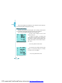
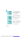
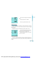
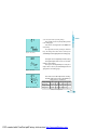
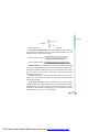
Press V/A to read voltage and current in the metering area.
The first screen: display U1, U2, U3 and
Ulnavg as in fig. 3.2.
U1=100.3V, U2=100.1V, U3=100.2V and
Ulnavg=100.2V. Load rating is 50%, inductive load,
imp energy is 8.8Kwh, communication state
normal, pulse output, DI1, DI2 and DI3 are open,
DI4 is close.
Fig 3.2 Three phase voltage
Press V/A, go to the second screen.
The second screen: display current of each
phase, I1, I2, I3 and In as in fig 3.3. I1=2.498,
I2=2.499, I3=2.491, In=0.008A.
Press V/A, go to the third screen.
Fig 3.3 Three phase current
32
PDF created with FinePrint pdfFactory trial version http://www.pdffactory.com
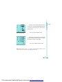
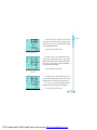
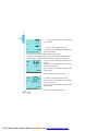
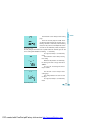
The third screen: display voltage of line to
line, U12, U23, U31 and average Ullavg, as in fig.
3.4, U12=173.2V, U23=173.3V, U31=173.1V,
Ullavg=173.2V.
Fig 3.4 Three phase voltage
Press V/A, go to the fourth screen.
The fourth screen: display current of each
phase and average current as in fig 3.5, I1=2.498A,
I2=2.499A, I3=2.491A, Iavg=2.496A.
Press V/A, go back to the first screen.
Fig 3.5 Three phase current
Note: when the meter is set to “2LL”, there is no phase voltage and phase current
screen, no first and second screen, only third and fourth screen.
33
PDF created with FinePrint pdfFactory trial version http://www.pdffactory.com
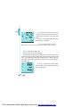
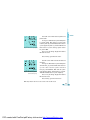
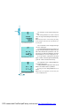
Press P, display power related data.
The first screen: display power of each phase
P1, P2, P3 and system total power Psum.
As in fig 3.6, P1=0.125KW, P2=0.125KW,
P3=0.125KW, Psum=0.375KW.
Fig 3.6 Three phase power
Press P, go to the second screen.
The second screen, display reactive power of
each phase, Q1, Q2, Q3 and system total reactive
power Qsum.
As in fig 3.7 Q1=0.217Kvar, Q2=0.216Kvar,
Q3=0.216Kvar and Qsum=0.649Kvar
Press P, go to the third screen.
Fig 3.7 Three phase reactire power
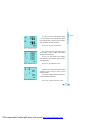
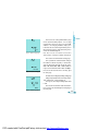
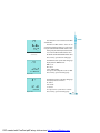
The third screen: display apparent power of
each phase S1, S2, S3 and system total apparent
power Ssum.
As in fig 3.8, S1=0.250KVA, S2=0.250KVA,
S3=0.249KVA and Ssum=0.749KVA.
Fig 3.8 Three phase apparent power
Press P, go to the fourth screen.
34
PDF created with FinePrint pdfFactory trial version http://www.pdffactory.com
The fourth screen: power factor of each
phase PF1, PF2, PF3 and system average power
factor PF. As in fig 3.9, PF1=0.500, PF2=0.500,
PF3=0.500 and PF=0.500.
Press P, go to the fifth screen.
Fig 3.9 Three phase PF
The fifth screen: system total power Psum,
system total reactive power Qsum, system total
apparent power and system average power factor.
As in fig 3.10, Psum=0.375, Qsum=0.649Kvar,
Ssum=0.749 and PF=0.500.
Press P, go to the sixth screen.
Fig 3.10 System power and
power factor
The sixth screen: system total power Psum,
system total reactive power Qsum, system total
apparent power Ssum and system frequency F.
As in fig 3.11, Psum=0.375KW, Qsum=0.
649Kvar, Ssum=0.749 KVA and F=50.00Hz.
Fig 3.11 System power and frequency
Press P, go to seventh screen.
PDF created with FinePrint pdfFactory trial version http://www.pdffactory.com
35
The seventh screen: display three phase
system power demand, power demand Dmd_P,
reactive power demand Dmd_Q and apparent
Dmd_S.
As in fig 3.12, Dmd_P=0.375KW, Dmd_Q=0.
649Kvar, Dmd_S=0.749KVA.
Fig 3.12 System power demand
Press P, go back to the first screen.
Note: There is not phase power to be display when the wiring of voltage setting is 2LL.
Press H, display power quality data.
The first screen, display THD of voltage.
The display will be THD of line to line voltage THD_U12, THD_U23, THD_U31
and THD of average line to line voltage THD_Ull when the wiring of voltage input
is 2LL. The display will be THD of phase voltage THD_U1, THD_U2, THD_U3
and THD of average phase voltage THD_Uln when the wiring of the voltage is
input 2LN or 3LN.
As in fig 3.13, THD of three phase voltage,
THD_U12=0.68%, THD_U23=0.68%, THD_U31=0.
68%, THD_Ull=0.68%.
Fig 3.13 THD of line voltage
36
PDF created with FinePrint pdfFactory trial version http://www.pdffactory.com
As in fig 3.14, when the wiring of the voltage
is set to be 2LN or 3LN, The display will be THD of
phase voltage. THD_U1=0.68%, THD_U2=0.68%,
THD_U3=0.68% and THD_Uln=0.68%.
Press H key, go to the second screen.
Fig 3.14 THD of phase voltage
The second screen: display THD of phase
current THD_I1, THD_I2, THD_I3 and THD of
average current THD_Iavg.
As in fig 3.15, THD of three phase voltage,
THD_I1=0.68%, THD_I2=0.68%, THD_I3=0.68%,
THD_Iavg=0.68%.
Fig 3.15 THD of line corrent
Press H key, go to the third screen.
The third screen: display three phase voltage
unbalance factor and three phase current
unbalance factor.
As in fig 3.16, voltage unbalance factor=0.8%,
current unbalance factor=0.9%.
Fig 3.16 Unbalance factor
Press H key, go back to the first screen.
37
PDF created with FinePrint pdfFactory trial version http://www.pdffactory.com
Press E key: display energy and real time
clock.
The first screen: display the consumption
energy Ep_imp=8.8Kwh
Press E key, go to the second screen.
Fig 3.17 Import energy
The second screen: Display the generation
energy Eq_exp=0.0
As in fig 3.18, Ep_exp=0.0Kwh
Press E key, go to the third screen.
Fig 3.18 Export energy
The third screen: Display absolute sum of imp
and exp energy Ep_total.
As in fig 3.19, Ep_total=8.8Kwh
Press E key, go to the fourth screen.
Fig 3.19 Total energy
38
PDF created with FinePrint pdfFactory trial version http://www.pdffactory.com
The fourth screen: Display algebraic sum of
imp and exp energy Ep_net.
As in fig 3.20, Ep_net=8.8Kwh.
Press E key, go to the fifth screen.
Fig 3.20 Net energy
The fifth screen: Display inductive reactive
energy Eq_imp.
As in fig 3.21, Eq_imp=15.2Kvarh
Press E key, go to the sixth screen.
Fig 3.21 Inducfive reactive energy
The sixth screen: Display the capacitive
reactive energy Eq_exp.
As in fig 3.22, Eq_exp=0.0Kvarh.
Press E key, go to the seventh screen.
Fig 3.22 Capacitive reactive energy
39
PDF created with FinePrint pdfFactory trial version http://www.pdffactory.com
The seventh screen: display absolute sum of
the reactive energy Eq_total.
As in fig 3.22, Eq_total=15.2Kvarh.
Press E key, go to the eighth screen.
Fig 3.23 Total reactive energy
The eighth screen: Display algebraic sum of
reactive energy.
As in fig 3.24, Eq_net=15.2Kvarh.
Press E key, go to the ninth screen.
Fig 3.24 Net reactive energy
The ninth screen: Display date. Format: mm:
dd:yyyy
As in fig 3.25, the date is Jan. 18, 2002.
Press E key, go to the tenth screen.
Fig 3.25 Date
40
PDF created with FinePrint pdfFactory trial version http://www.pdffactory.com
The tenth screen: Display time. Format: hh:
mm:ss.
As in fig 3.26, the time is 13:20:29.
Press E key, go back to the first screen.
Fig 3.26 Time
Statistics Display
Press P and V/A Keys simultaneously, the Max and Min value of metering
data will display on the screen. The time stamp can be access through
communication.
Press the P and V/A keys simultaneously, go to the statistics screen.
The first screen: Display the Max value of voltage.
The Max label display on up right of letter U.
As in fig 3.27, U1_max=100.3V, U2_max=100.
1 and U3_max=100.2V.
Fig 3.27 Max phase voltage
Press P key, to display the Min value of voltage. The Min label display on the
low right of the letter U. Press P key again, go back to display the Max value of
voltage.
41
PDF created with FinePrint pdfFactory trial version http://www.pdffactory.com
As in fig 3.28 U1_min=0.0V, U2_min=0.0V and
U3_min=0.0V.
Fig 3.28 Min phase voltage
Press V/A key, go to the next screen.
The second screen: Display the Max and Min value
of line to line voltage.
The third screen: Display the Max and Min value of Current.
The fourth screen: Display the Max and Min value of power and power factor.
The fifth screen: Display the Max and Min value of Demand and frequency.
The second screen: Max value of the line to line
voltage.
As in fig 3.29, U12_max=173.2V, U23_max=173.
3V and V31_max=173.1V
Press P key to change display from Max to Min
and vice versa.
Fig 3.29 Max line voltage
Press V/A key, go to the next screen.
The third screen: Max value of the current.
As in fig 3.30, I1_max=2.498A, I2_max=2.499A
and I3_max=2.491A.
Press P key to change display from Max to Min
and vice versa.
Fig 3.30 Max Current
42
Press V/A key, go to the next screen.
PDF created with FinePrint pdfFactory trial version http://www.pdffactory.com
Fig 3.31 Max value of system power
The fourth screen: Max value of power and
power factor.
As In fig 3.31, Max value of system total power
P_max=0.375W , Max value of system total
reactive power Q_max=0.649Kvar, Max value of
system apparent power S_max=0.749KVA and
Max value of system average power factor
PF_max=1.000.
Press P key to change display from Max to
Min and vice versa.
Press V/A key, go to the next screen.
Fig 3.32 Max value of system
demand and frequency
The fifth screen: Max value of demand and
frequency
As in fig 3.32, Max value of system total power
demand Dmd_P_max=0.375KW, Max value of
system total reactive power dem and
Dmd_P_max=0.649Kvar, Max value of system
total apparent power demand Dmd_P_max=0.
749KVA and Max value of system frequency.
Press P key to change display from Max to
Min and vice versa.
Press V/A key, go to the next screen.
Note: Only Ai205-P2 OR -P3 has the function of Max and Min record.
43
PDF created with FinePrint pdfFactory trial version http://www.pdffactory.com
Meter Parameter Setting
Under the metering data display mode, press the H and V/A key
simultaneously, get into the meter parameter setting
• Note
mode.
The setting should be
In the meter parameter setting mode, press H key to
done by the professional
personnel after he has
move cursor. Right move one digit each time. Press P for
read this user’s manual
increasing and press E for decreasing. Press V/A for
a n d u n d e r st a n d t h e
acknowledgment
and going to the next setting item page.
application situation.
Press H and V/A page keys simultaneously to exit in any
setting item page.
• Note
Access code needed for going into the parameter
When pressing H and V/
setting mode. Only the person who know the access code
A keys simultaneously to
can do the parameter setting. The access code is 4 digits
exit the setting mode, the
decimal number. It is from 0000 to 9999. The factory
setting of current page
will not be stored.
default is 0000. After key in the right access code, press
V/A to go to the first parameter setting page, otherwise go
back to the metering data display page.
As in fig 3.33 is access code page .
Fig 3.33 access code page
44
PDF created with FinePrint pdfFactory trial version http://www.pdffactory.com
Fig 3.34 Address setting page
The first screen: setting Ai205 address page
for the communication purpose. It is any digit
number from 1 to 247. As in fig 3.34, the Ai205
Address is 17. Changing method is simple, press
H to move the curser to the digit wanted, press P
for increasing and press E for decreasing. Press
V/A for the acknowledgment.
Note: Each meter on same RS485 net should have
different address according to the Modbus-RTU protocol.
Fig 3.35 Baud rate setting page
Fig 3.36 Voltage input wiring
The second screen: Baud rate setting page
The asynchronies communication setting of
the Ai205 is 8 data bit, no parity, 1 star bit and 1
stop bit. Baud rate could be one of the seven,
600, 1200, 2400, 4800, 9600, 19200, 38400. as
in fig 3.35, the baud rate of the Ai205 is 19200bps.
Press P or E to select one. Press V/A Key, go to
the next page.
The third screen: voltage input wiring setting page
Voltage input could be one of the three modes,
3LN, 2LN and 2LL. (refer to chapter 2)
As in fig 3.36, the setting of voltage input mode
is 3LN.
Press P or E to select from 3LN, 2LN and 2LL.
Press V/A key for acknowledgment and going to
the next page.
PDF created with FinePrint pdfFactory trial version http://www.pdffactory.com
45
Fig 3.37 Current input wiring
Fig 3.38 PT primary
Fig 3.39 PT secondary
46
The fourth screen: Current input wiring setting
page
Current input wiring could be one of the three
modes, 3CT, 2CT and 1CT. (Refer to chapter 2)
As in fig 3.37, current input mode setting is
3CT. Press P or E keys to select from 3CT, 2CT
and 1CT. Press V/A key for acknowledgment and
going to the next setting page.
The fifth screen: PT primary rating voltage PT1
setting page
PT1 value is an integer from 100 to 500,000.
The unit is volt.
As in fig 3.38, PT1=1000V, press P, E and H
to c hange th e value . Press V/A key for
acknowledgment and going to the next setting page.
The sixth screen: PT secondary rating voltage
PT2 setting page.
PT2 value is an integer from 100 to 400. The
unit is volt.
As in fig 3.39, PT2=100V, press P, E and H to
change the value. Press V/A key for
acknowledgment and going to the next setting page.
Note: If there is no PT on the voltage input side of Ai205, the PT1 and PT2 should be the
PDF created with FinePrint pdfFactory trial version http://www.pdffactory.com
same and equal to the input rating voltage.
Fig 3.40 CT primary
Fig 3.41 DO mode
The seventh screen: CT primary rating current
CT1 setting page
CT1 value is an integer from 5 to 10000. The
unit is Amp.
As in fig 3.40, CT1=5A, pressing P, E and H
keys to change the value. Press V/A key for
acknowledgment and going to the next setting page.
The eighth screen: Digital output mode setting
The digital output mode can be set as alarm
output or pulse output.
As in fig 3.41, the digital output is set as pulse
output. Press V/A key for acknowledgment and
going to the next setting page.
The ninth screen: DO1 output item selecting
The DO1 output can be one of the following 8
energy items as in Table3.2.
Setting number
Energy item
Setting Number
Fig 3.42 DO1 output item
Energy item
0
1
2
3
4
No output Ep_imp Ep_exp Eq_imp Eq_exp
5
6
7
8
Ep_total Ep_net Eq_tota Eq_net
Table3.2 DO1 output item
PDF created with FinePrint pdfFactory trial version http://www.pdffactory.com
47
The tenth screen: DO2 output item selecting
The DO2 output can be one of the 8 energy
items as in Table3.2.
Fig 3.43 DO2 output item
The eleventh screen: The DO pulse width
setting
The DO pulse width is integer from 1 to 50.
One digit represents 20ms.
As in fig 3.44, the pulse width is set to be 2,
that is 2x20=40ms.
Fig 3.44 Pulse width
Fig 3.45 Pulse rate
The twelfth screen: Energy pulse rate setting
page.
Pulse rate means the energy value per pulse.
It can be the integer of 1 to 6000. One digit
represents 0.1Kwh or 0.1Kvarh.
As in fig 3.45, the pulse rate is 10.
48
PDF created with FinePrint pdfFactory trial version http://www.pdffactory.com
Fig 3.46 Relay1 mode
The thirteenth screen: Relay1 mode setting
page
There are two relay output in Ai205. There
are two relay output modes for selection, one is
latching, the other is momentary. For the latching
mode, the relay can be used to output two statues
on or off. For the momentary mode, the output of
the relay changes from off to on for a period of time Ton and than goes off. Ton
can be setting from 50-300ms. 0: latching 1: momentary
Fig 3.47 Relay1 closing time
As in fig 3.46, Relay1 is set momentary
mode.
The fourteenth screen: Relay1 closing
time setting
When the relay mode is set momentary,
the closing time Ton is integer from 50 to
3000ms.
As in fig 3.47, the closing time Ton of
relay1 is 50ms.
The fifteenth screen: Relay2 mode
setting page
The setting method is the same as that
of relay1.
As in fig 3.48, Relay2 is set momentary
mode.
Fig 3.48 Relay2 mode
PDF created with FinePrint pdfFactory trial version http://www.pdffactory.com
49
The sixteenth screen: Relay2 closing time
setting
The setting method is the same as that of
relay1. As in fig 3.49, the closing time Ton of relay1 is
50ms.
Note: If the relay mode is set to be latching, the setting
of relay closing time Ton do not has any interference on
Fig 3.49 Relay2 closing time
Fig 3.50 Back light “on”time
the relay state.
The seventeenth screen: Display back light
“on” time setting page
The backlight will go to“off ”for the purpose of
energy saving and component duration if the key
does not be touched for a period time. The “on”
time can be set from 0 to 120 Minute. The back
light will always be “on” if the setting value is 0.
As in fig 3.50, the setting time of the back
light is 5 minute. The back light will automatically
go to “off ” if there is no touch on the keys.
The eighteenth screen: Sliding window time
of demand setting page
Sliding window time of demand is from 1 to 30
Minute. The window slid once per Minute.
As in fig 3.51, the sliding window time is 15
Minute.
Note: There are not eighteenth screen to twenty first
Fig 3.51 Sliding window time
50
screen in Ai205-P0 and -P1.
PDF created with FinePrint pdfFactory trial version http://www.pdffactory.com
Fig 3.52 Clearance of the max
and min value
Fig 3.53 Date
Fig 3.54 Time
The nineteenth screen: Clearance of the Max
and Min value
The Max and Min statistics value can be
cleared by operating the front keys. Clear means
to begin record new Max and Min statistics value.
As in fig 3.52, press E or P keys to select Yes or No.
Yes: Clear the Max and Min statistics value
No: Do not clear the Max and Min statistics value
Press V/A key, go to the next setting page.
The twentieth screen: System date setting page
Display format is MM:DD:YYYY
MM: 1 to 12
DD: 1 to 31
YYYY: 2000 to 2099
As in fig 3.53, the setting date is Jan. 18, 2002.
Press V/A key, go to next setting page.
The twenty first screen: system time setting page
The display format is hh:mm:ss.
hh: 0 to 23
mm: 0 to 59
ss: 0 to 59
As in fig 3.54, the system time is 13:20:29
Press V/A key, go to next setting page.
PDF created with FinePrint pdfFactory trial version http://www.pdffactory.com
51
Fig 3.55 Access code setting
The twenty second screen: Access code
setting page (It is the eighteenth screen in Ai205)
This is the last screen of the setting page. The
access code can be changed in this setting page.
It is important to remember the new access code.
As in fig 3.55, the access code is 0001. Press
the V/A key, let the access code be stored in
Ai205 and go back to the first setting page. All the
setting has been finished. Press H and V/A keys,
exit the setting mode.
Introduction of measurement and functions of Ai205
Almost all electric parameters in power systems can be measured by Ai205
series intelligent power meter. Some parameters that do not be familiar by users
will be introduced in this part.
Voltage (U): True RMS value of three phase voltages, three line to line voltages
and their average are measured and displayed in Ai205.
Current (I): True RMS value of three phase currents, neutral current and
their average are measured and displayed in Ai205.
Power (P): Three phase power and system total power are measured and
display in Ai205.
Reactive power (Q): Three phase reactive power and system total reactive
power are measured and displayed in Ai205.
Apparent power (S): Three phase apparent power and system total apparent
power are measured and displayed in Ai205.
Frequency (F): The frequency of U1 phase voltage input is measured as
system frequency.
Energy (Kwh): Energy is time integral of power. The unit is Kwh. As power
has direction, positive means consumption and negative means generating. So
the energy has also the nature of consumption or generating.
52
PDF created with FinePrint pdfFactory trial version http://www.pdffactory.com
Import (imp): Consumption energy
Export (exp): Generating energy
Total: Absolute sum of import and export energy
Net: Algebraic sum of import and export energy
Reactive power: Reactive energy is time integral of reactive power. The unit
is Kvarh. As reactive power has direction, positive means inductive and negative
means capacitive, so the reactive energy has also got the nature of inductive and
capacitive.
Import (imp): Inductive reactive energy
Export (exp): Capacitive reactive energy
Total: Absolute sum of import and export reactive energy
Net: Algebraic sum of import and export reactive energy
Each of the four reactive energies is measured and stored independently.
Demand: Demand of power, reactive power and apparent power. The demand
statistics method in Ai205 is sliding window. The sliding window time can be
chose between 1 to 30 Minutes. The window slides one Minute each time. For
example, the sliding window time is supposed to be 3 Minute. If average power
of the first Minute is 12, average power of the second Minute is 14 and average
power of the third Minute is 10, then the total demand of the 3 minutes is
(12+14+10)/3=12 at the end of the three Minute. If another Minute passed, the
average power of the Minute is 8, then the total power demand of the last three
Minute is (14+10+8)/3=10 at the end of the fourth Minute.
Crest factor (CF): The crest factor is used to express the distortion of
waveform. This is an important factor to scale the influence to the system insulation.
The expression is as following:
In the expression, U1 is the RMS of fundamental and Uh is the RMS of the hth harmonic.
53
PDF created with FinePrint pdfFactory trial version http://www.pdffactory.com
The function of Crest factor only exists in Ai205-P2 or -P3.
Total harmonic distortion: This factor is often used to express the power quality
of the electric power system. The expression is as following,
In the expression, U1 is the RMS of fundamental and Uh is the RMS of the hth
harmonic.
This function exists in Ai205.
Each harmonic rate: The percentage of each harmonic divided by fundamental.
Total Even harmonics distortion: Root of the sum of each even harmonics
square.
Total Odd harmonics distortion: Root of the sum of each odd harmonics square.
Telephone Interference Factor (THFF): The interference factor to telephone
communication system. The expression of the THFF is as following,
In the expression, the Uh is the voltage of the hth harmonic and the Ph is
coefficient which is defined by CCITT committee.
The function of the THFF exists in Ai205.
K factor: This is an important factor to scale the power quality of current.
54
PDF created with FinePrint pdfFactory trial version http://www.pdffactory.com
In the expression, the Fn is the RMS of the nth harmonic.
Three phase unbalance factor: three phase voltage unbalance factor and
three phase current unbalance factor can be measured in Ai205-P2 or -P3. The
unbalance factor is express in percentage.
Voltage unbalance factor =
The Max different value of three voltages
Average value of three voltages
Current unbalance factor =
The Max different value of the three currents
Average value of three currents
Max/Min statistics: The maximum and minimum value of the metering data
is stored in unvaluntable RAM and can be accessed or cleared from front panel or
through communication in Ai205-P2 or -P3. These metering data is phase voltage,
line to line voltage, current, power, reactive power, apparent power, power
factor, frequency, demand.
Real time clock: There is a real time clock in the Ai205-P2 or -P3. The date,
month, year, hour, minute and second can be read or set from front panel or
through communication.
Phase Angle different: the phase angel difference gives the phase angle
relationship between the voltage and current. It is from 0 to 360o. When the wiring
of voltage input is set to be 2LL, it gives the phase difference U23, i1, i2 and i3
relative to U12. When the wiring of voltage input is set to be 2LN and 3LN, it gives
the phase difference U2, U3, i1, i2, i3 relative to U1.
55
PDF created with FinePrint pdfFactory trial version http://www.pdffactory.com
Over limit alarming
In Ai205-P2 or -P3, when the metering data is over the pre-setting limit and
over presetting period of time, the over limit alarming will be picked up. The over
limit value and time will be recorded and the maximum number of records is 9.
The digital output (DO) can be used as light or sound alarming trigger.
There can be maximum 9 inequations related to the over limit alarming. Any
satisfaction of the inequations will trigger the over limit alarming. Any one of the 9
equations can be assigned to one of the digital output (DO). An example is given
in the following to describe how the first inequation is being set and determined.
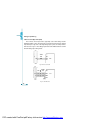
Start :
Enable inequation1
Var1 := Parameter
Enable the first inequation
Let the variable1 to represent the
alarming parameter
Set
the limit value to the Ref1
Ref1 := Value
Set
the
time limit to the Limit_t
Limit_t := time
Select
the
inequatity sign > or <
Setting inequality_sign
Select
the
related
digital output (DO)
Setting associatedDO
Determine
if
the
parameter
is over the limit
If Var1 inequality Ref1=”True” and
and
over
the
time
limit
Last_time>Limit_t
If it is true, then
Then
Record
the value, date and time
{ record envent
Setting
the
related Digital output (DO)
Output associatedDO }
Finish
end
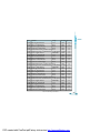
The related registers should be preset in order to finish the above process.
The registers are preset through communication.
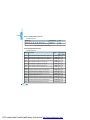
56
PDF created with FinePrint pdfFactory trial version http://www.pdffactory.com
Inequation enable register: register EN_INEQU, bit0~bit8 corresponding to 1
to 9 inequation.
Bit(n)=0 forbid the nth inequation
Bit(n)=1 enable the nth inequation
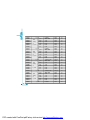
The 9 variables (var1 to var9) can be any of the 34 parameters.
Var number
0
1
Var name
Var number
F
9
V1
10
Var name
I1
Var number 18
I2
19
Var name
Q1
Var number 27
Q2
28
Var name
PF2 PF3
2
V2
11
I3
20
Q3
29
PF
3
4
5
6
7
8
V3
12
Vlnavg
13
V12
14
V23
15
V31
16
Vllavg
17
Iavg
21
In
22
P1
23
P2
24
P3
25
Psum
26
Qsum
30
S1
31
S2
32
S3
33
Ssum
34
PF1
U_unbl
I_unbl Dmd_P Dmd_Q Dmd_S
Table 3.3 parameter name and number
Limit setting register: register Ref1 to Ref9
The setting of the Ref register should be the up limit or the low limit of the
parameter. The range of the parameter limit is related to the format of the register.
Time limit setting register: register Limit_t
Limit_t is the time limit. It is an integer from 0 to 255. One digit is 300ms. Zero
means no time limit. Trigger the record and alarming output immediately on the
over limitation. All the inequations have the same time limit. If the Limit_t=20, the
time limitation is 20x300=6000ms.
Inequation sign register: INEQU_Sign1 to INEQU_Sign9
INEQU_Sign=0, select <, the low limit
INEQU_Sign=1, select >, the up limit
57
PDF created with FinePrint pdfFactory trial version http://www.pdffactory.com
The DO select register:
AssociatedDO1 register bit0~bit8 correspond to the first to ninth inequation.
Bit(n)=0, DO1 do not associate with the nth inequation
Bit(n)=0, DO1 associate with the nth inequation
AssociatedDO2 register bit0~bit8 correspond to the first to ninth inequation.
Bit(n)=0, DO2 do not associate with the nth inequation
Bit(n)=0, DO2 associate with the nth inequation
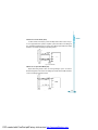
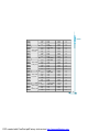
Example:
If current I1 goes over the up limit and time limit 15 Seconds, trigger the over
limit alarm record and DO1 output. The CT ratio of the current I1 is 200:5. The up
limit of current I1 is set to be 180A. The setting of the registers is as following.
Enable the inequation1: EN_INEQU register bit(0)=1
The current I1 is number 9 in Table3.3. The setting of the Var1 is 9.
The relation of real current and the data stored in register is,
Real current=(data in registerxCT1/5)/1000
The CT1 is 200 and up limit of current is 180A, then the data in register is
4500. The setting of the Ref1 is 4500.
Time limit is 15 Seconds and the one digit is 300ms, then the setting of Limit_t1
is 50.
As it is the up limit, the INQU_Sign1 should be 1.
Use DO1as alarm signal output, then the bit0 of the associatedDO1 should be
1.
The output mode of DO should be set alarming through front panel or
communication.
58
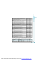
PDF created with FinePrint pdfFactory trial version http://www.pdffactory.com
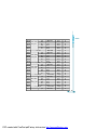
Address
Content
Remark
Alarming record addr
Alarming parameter number: Var
Refer to Table3.3
Addr +1
Addr +2
Alarming value
Year
Record the value of alarming
parameter
Addr+3
Addr+4
Month
Date
Alarming date
Addr+5
Addr+6
Hour
Minute
Addr+7
Second
Alarming time
Table3.4 Alarm record
Only recent 9 groups of the alarming record can be stored in memory of
Ai205-P2 or -P3. The format of the record is,
When the alarming parameter resume normal (no longer over the limit), it is
also recorded. User can get the total period of over limit time.
Note: when the alarming parameter resume to normal, the highest bit of Var
bit15 is set to be 1.
Energy pulse output: The two digital outputs (DO) can be select as energy
pulse output. Any two of the 8 energy and reactive energy can be assigned to be
as the pulse output. The pulse width and pulse ratio can be set, while pulse width
means how long the duration of the pulse is and pulse ratio means how much
energy that one pulse is represented. When the energy accumulates to the setting
limit, there will be a pulse output from the assigned DO port.
Pulse output assignment register: any integer from 0 to 8. The digit 0 means
no assignment, while 1 to 8 corresponding to Ep_imp, Ep_exp, Eq_imp, Eq_exp,
Ep_total, Ep_net, Eq_total and Eq_net respectively.
59
PDF created with FinePrint pdfFactory trial version http://www.pdffactory.com
Pulse ratio register: any integer from 1 to 6000. One digit represents 0.1Kwh
or Kvarh. This value is the minimum resolution of energy pulse output.
Pulse width setting register: any integer from 1 to 50. One digit represents
20ms.
The minimum time interval between two adjoining output pulses is 20ms in
Ai205. If the pulse width is 20ms, then maximum number of output pulses is 25 in
one Second. If the pulse width is 80ms, then the maximum number of output
pulse is 10.
In practice the pulse width and the pulse ratio are selected according to system
power. The relation of the two parameters should satisfied following expression,
Pulse ratio >
(pulse width + 1) x Pmax
18000
In the expression, the Pmax is the maximum power or reactive power. The
unit is KW or Kvar. Recommend pulse ratio is 3 to 5 times the right side value of
the above expression.
Relay output: The two relay output (option) in Ai205 can be used to control
electric switch or equipment. There are two output mode of the relay, latching or
momentary. Momentary mode is often used to control the electric switch. The
closing time interval can be selected between 50ms to 3000ms.
60
PDF created with FinePrint pdfFactory trial version http://www.pdffactory.com
Chapter 4 Communication
Introducing Modbus Protocol
Format of Communication
Data Address Table
61
PDF created with FinePrint pdfFactory trial version http://www.pdffactory.com
Introducing Modbus Protocol
The Modbus RTU protocol is used for communication in Ai205. The data
format and error check method are defined in Modbus protocol. The half duplex
query and respond mode is adopted in Modbus protocol. There is only one
master device in the communication net. The others are slave devices, waiting
for the query of the master.
Transmission mode
The mode of transmission defines the data structure within a frame and the
rules used to transmit data. The mode is defined in the following which is compatible
with Modbus RTU Mode*.
Coding System
8-bit binary
Start bit
1
Data bits
8
Parity
no parity
Stop bit
1
Error checking
CRC check
Modbus is trademark of Modicon, Inc.
62
PDF created with FinePrint pdfFactory trial version http://www.pdffactory.com
Framing
Address
Function
Data
Check
8-Bits
8-Bits
N x 8-Bits
16-Bits
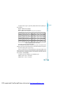
Table4.1 Data Frame Format
Address Field
The address field of a message frame contains eight bits. Valid slave device
addresses are in the range of 0~247 decimal. A master addresses a slave by
placing the slave address in the address field of the message. When the slave
sends its response, it places its own address in this address field of the response
to let the master know which slave is responding.
Function Field
The function code field of a message frame contains eight bits. Valid codes
are in the range of 1~255 decimal. When a message is sent from a master to a
slave device the function code field tells the slave what kind of action to perform.
Code
Meaning
Action
01
02
Read Relay output Status
Read Digital Input (DI) Status
Obtain current status of Relay Output
Obtain current status of Digital Input
03
Read Data
Obtain current binary value in one
or more registers
05
16
Control Relay Output
Preset Multiple-Registers
Force Relay to a state of on or off
Place specific binary values into a series
of consecutive Multiple-Registers
Table4.2 Function Code
63
PDF created with FinePrint pdfFactory trial version http://www.pdffactory.com
Data Field
The data field is constructed using sets of two hexadecimal digits, in the range
of 00 to FF hexadecimal. The data field of messages sent from a master to slave
devices contains additional information which the slave must use to take the action
defined by the function code. This can include items like discrete and register
addresses, the quantity of items to be handled, and the count of actual data bytes
in the field. For example, if the master requests a slave to read a group of holding
registers (function code 03), the data field specifies the starting register and how
many registers are to be read. If the master writes to a group of registers in the
slave (function code 10 hexadecimal), the data field specifies the starting register,
how many registers to write, the count of data bytes to follow in the data field, and
the data to be written into the registers.
If no error occurs, the data field of a response from a slave to a master contains
the data requested. If an error occurs, the field contains an exception code that
the master application can use to determine the next action to be taken. The data
field can be nonexistent (of zero length) in certain kinds of messages.
Error Check Field
Messages include an error’s checking field that is based on a Cyclical
Redundancy Check (CRC) method. The CRC field checks the contents of the
entire message. It is applied regardless of any parity check method used for the
individual characters of the message. The CRC field is two bytes, containing a 16
bit binary value. The CRC value is calculated by the transmitting device, which
appends the CRC to the message.
The receiving device recalculates a CRC during receipt of the message, and
compares the calculated value to the actual value it received in the CRC field. If
64
PDF created with FinePrint pdfFactory trial version http://www.pdffactory.com
the two values are not equal, an error results. The CRC is started by first
preloading a 16-bit register to all 1’s. Then a process begins of applying successive
8-bit bytes of the message to the current contents of the register. Only the eight
bits of data in each character are used for generating the CRC. Start and stop
bits, and the parity bit, do not apply to the CRC. During generation of the CRC,
each 8-bit character is exclusive ORed with the register contents. Then the
result is shifted in the direction of the least significant bit (LSB), with a zero filled
into the most significant bit (MSB) position. The LSB is extracted and examined.
If the LSB was a1, the register is then exclusive ORed with a preset, fixed value.
If the LSB was a 0, no exclusive OR takes place. This process is repeated until
eight shifts have been performed. After the last (eighth) shift, the next 8-bit byte
is exclusive ORed with the register current value, and the process repeats for
eight more shifts as described above. The final contents of the register, after all
the bytes of the message have been applied, is the CRC value. When the CRC is
appended to the message, the low-order byte is appended first, followed by the
high-order byte.
Format of communication
Explanation of frame
Addr Fun
06H
03H
Data start
Data start
Data #of
Data #of
CRC16
CRC16
reg hi
reg lo
regs hi
regs lo
Hi
Lo
00H
00H
00H
21H
84H
65H
Table4.3 Explanation of frame
In table4.3, the meaning of each abbreviated word is,
Addr: address of slave device
65
PDF created with FinePrint pdfFactory trial version http://www.pdffactory.com
Fun: function code
Data start reg hi: start register address high byte
Data start reg lo: start register address low byte
Data #of reg hi: number of register high byte
Data #of reg lo: number of register low byte
CRC16 Hi: CRC high byte
CRC16 Lo: CRC low byte
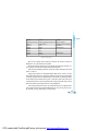
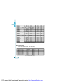
1.Read Status of Relay
Function Code 01
This function code is used to read status in Ai205.
1=On
0=Off
There are 2 Relays in Ai205. The Address of each Relay is
Relay1=0000H and
Relay2=0001H.
The following query is to read Relay Status of Ai205 Number 17.
Query
Addr Fun
11H
01H
relay start
relay start
relay #of relay #of
CRC16
CRC16
reg hi
reg lo
regs hi
regs lo
Hi
Lo
00H
00H
00H
02H
BFH
5BH
Table4.4 Read the status of Relay1 and Relay2 Query Message
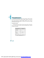
Response
The Ai205 response includes the Ai205 address, function code, quantity of
data byte, the data, and error checking. An example response to read the status
of Relay1 and Relay2 is shown as Table4.5. The status of Relay1 and Relay2 is
responding to the last 2 bit of the data.
66
PDF created with FinePrint pdfFactory trial version http://www.pdffactory.com
Relay1: bit0
Relay2: bit1
Address
Function code
Byte count
Data
CRC high
CRC low
11H
01H
01H
02H
D4H
89H
Table4.5 Relay status responds.
The content of the data is,
7
6
5
4
3
2
1
0
0
0
0
0
0
0
1
0
MSB
Relay1 = OFF (LSB ),
LSB
Relay2=ON (Left to LSB )
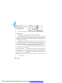
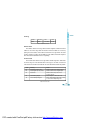
2 Read the Status of DI
Function Code 02
1=On
0=Off
There are 4 DIs in Ai205. The Address of each DI is
DI1=0000H, DI2=0001H, DI3=0002H and DI4=0003H.
The following query is to read the 4 DI Status of Number 17 Ai205.
Query
Addr
11H
Fun
02H
DI start
DI start
DI num
DI num
CRC16
CRC16
addr hi
addr lo
hi
lo
hi
lo
00H
00H
00H
04H
7BH
59H
Table4.6 Read 4 DIs Query Message
Response
The Ai205 response includes the Ai205 address, function code, quantity of data
characters, the data characters, and error checking. An example response to
read the status of 4 DIs is shown as Table4.7. The status of each is responding
to the last 4 bit of the data.
67
PDF created with FinePrint pdfFactory trial version http://www.pdffactory.com
DI1: bit0
DI2: bit1
Table 4.7 Read Status of DI
addr
11H
Fun
02H
DI3: bit2
Byte count
01H
DI4: bit3
Data
03H
CRC16 hi
E5H
CRC16 lo
49H
The content of the data is,
7
0
6
0
MSB
DI1=On
5
0
4
0
3
0
DI2=On
2
0
1
1
0
1
LSB
DI4=Off
DI3=Off
3 Read Data (Function Code 03)
Query
This function allows the master to obtain the measurement results of Ai205.
Table4.8 is an example to read the 3 measured data (F, V1 and V2) from slave
device number 17, the data address of F is 0130H, V1 is 0131H and V2 is
0132H.
Addr
Fun Data start Data start
addr hi
addr lo
Data #of
regs hi
Data #of
regs lo
CRC16
regs hi
CRC16
regs lo
11H
03H
00H
03H
06H
A8H
01H
30H
Table 4.8 Read F,V1,V2 Query Message
Response
The Ai205 response includes the Ai205 address, function code, quantity of
data byte, data, and error checking. An example response to read F, V1 and V2
(F=1388H (50.00Hz), V1=03E7H (99.9V), V2=03E9H (100.1V) is shown as
Table4.9.
Addr
68
11H
Fun
Byte
03H
count hi
06H 13H
Data1 Data1 Data 2 Data2 Data3 Data3
Lo
88H
hi
03H
lo
E7H
hi
03H
lo
E9H
CRC16 CRC16
hi
7FH
lo
04H
Table4.9 Read F, V1 and V2 Message
PDF created with FinePrint pdfFactory trial version http://www.pdffactory.com
4 Control Relay(Function Code 05)
Query
This message forces a single Relay either on or off. Any Relay that exists
within the Ai205 can be forced to be either status (on or off). The address of
Relays starts at 0000H (Relay1=0000H, Relay2=0001H). The data value FF00H
will set the Relay on and the value 0000H will turn it off; all other values are illegal
and will not affect that relay.
The example below is a request to the Ai205 number 17 to turn on Relay1.
Addr
Fun
DO addr
hi
DO addr
Lo
Value
Hi
Value
lo
CRC16
hi
CRC16
lo
11H
05H
00H
00H
FFH
00H
8EH
AAH
Table4.10 Control Relay Query Message
Response
The normal response to the command request is to retransmit the message
as received after the Relay status has been altered.
Addr Fun Relay address Relay address Value
high
Low
High
Value
low
CRC
high
CRC
low
11H
00H
8EH
AAH
05H 00H
00H
FFH
Table4.11 Control Relay Response Message
5 Preset / Reset Multi-Register(Function Code 16)
Query
Function 16 allows the user to modify the contents of a Multi-Register. Any
Register that exists within the Ai205 can have its contents changed by this
message.
The example below is a request to an Ai205 number 17 to Preset Ep_imp
(17807783.3KWH), while its Hex Value 0A9D4089H. Ep_imp data address is
0156H and 0157H.
69
PDF created with FinePrint pdfFactory trial version http://www.pdffactory.com
Address
11H
Function
10H
Data start register high
Data start register low
01H
56H
Data register high
Data register low
00H
02H
Byte count
Value high
04H
0AH
Value low
Value high
9DH
40H
Value low
CRC high
89H
4DH
CRC low
B9H
Table4.12 Preset KWH Query Message
Response
The normal response to a preset Multi-Register request includes the Ai205
address, function code, data start register, the number of registers, and error
checking.
70
Address
Function code
11H
10H
Data start address high
Data start address low
01H
56H
Data register high
00H
Data register low
02H
CRC high
CRC low
A2H
B4H
Table4.13 Preset Multi-Registers Response Message
PDF created with FinePrint pdfFactory trial version http://www.pdffactory.com
Data address table
The measured data in shadow only exists in Ai205-P2 or -P3.
Basic Analog measurements
Function code: 03
Address Parameter
Range
Object Type Type of access
0130H
Frequency F
0~7000
word
R
0131H
0132H
Phase Voltage V1
Phase Voltage V2
0~65535
0~65535
word
word
R
R
0133H
0134H
Phase Voltage V3
0~65535
Average Phase Voltage Vlnavg 0~65535
word
word
R
R
0135H
0136H
Line Voltage V12
Line Voltage V23
0~65535
0~65535
word
word
R
R
0137H
0138H
Line Voltage V31
Average Line Voltage Vllavg
0~65535
0~65535
word
word
R
R
0139H Current I1
013AH Current I2
0~65535
0~65535
word
word
R
R
013BH Current I3
013CH Average Current Iavg
0~65535
0~65535
word
word
R
R
013DH Neutral Line Current In
013EH Phase Power P1
0~65535
-32768~32767
word
Integer
R
R
013FH
0140H
Phase Power P2
Phase Power P3
-32768~32767
-32768~32767
Integer
Integer
R
R
0141H
0142H
System Power Psum
Phase Reactive Power Q1
-32768~32767
-32768~32767
Integer
Integer
R
R
0143H
0144H
Phase Reactive Power Q2
Phase Reactive Power Q3
-32768~32767
-32768~32767
Integer
Integer
R
R
71
PDF created with FinePrint pdfFactory trial version http://www.pdffactory.com
0145H System Reactive Power Qsum
-32768~32767
Integer
R
0146H Phase Apparent Power S1
0~65535
word
R
0147H Phase Apparent Power S2
0~65535
word
R
0148H Phase Apparent Power S3
0149H System Apparent Power Ssum
0~65535
0~65535
word
word
R
R
014AH Phase Power Factor PF1
014BH Phase Power Factor PF2
-1000~1000
-1000~1000
Integer
Integer
R
R
014CH Phase Power Factor PF3
014DH System Power Factor
-1000~1000
-1000~1000
Integer
Integer
R
R
014EH Voltage Unbalance Factor U_unbl
014FH Current Unbalance Factor I_unbl
0~3000
0~3000
word
word
R
R
0150H Load Type RT (L/C/R)
0151H Power Demand Dmd_P
76/67/82
-32768~32767
word
Integer
R
R
0152H Reactive power Demand Dmd_Q
0153H Apparent Power Demand Dmd_S
-32768~32767
0~65535
Integer
word
R
R
Table 4.14 Metering data address table
The Relationship between numerical value in register of Ai205 and the real
physical value is as following table. (Rx is the numerical value in register of
Ai205)
Parameter
Relationship
Unit
V12, V23, V31, Vllavg
Current I1, I2, I3, Iavg, In
U=Rx ×(PT1/PT2)/10
I =Rx ×(CT1/5)/1000
Volt(V)
Amp(A)
Power P1, P2, P3, Psum,
Power Demand Dmd_P
P=Rx ×(PT1/PT2)×(CT1/ 5)
Watt(W)
Reactive Power Q1, Q2, Q3, Qsum,
Reactive Power Demand Dmd_Q
Q=Rx ×(PT1/PT2)×(CT1/5)
Var
Apparent Power S1, S2, S3, Ssum
Demand Power Dmd_S
S=Rx ×(PT1/PT2)×(CT1/5)
VA
Voltage V1, V2, V3,
72
PDF created with FinePrint pdfFactory trial version http://www.pdffactory.com
Power Factor PF1, PF2, PF3, PF
PF=Rx/1000
NA
Frequency
F=Rx/100
Hz
Load Type RT (L/C/R)
ASCII of L, C, R
NA
Voltage or Current Unbalance
Low 8 bit of Register
unbl=(Rx/1000)× 100%
NA
Factor U_unbl, I_unbl
Table 4.15 Measareing data convert table
Energy measurement
Function code : 03 Read 16, Preset
Address
Parameters
Range
Object
Type
Type of
access
0156H(High 16 Bit)
0157H(Low 16 bit)
Import Energy Ep_imp
0~99999999.9
Dword
R/W
0158H(High 16 Bit)
0159H(Low 16 bit)
Export Energy Ep_exp
0~99999999.9
Dword
R/W
015AH(High 16 Bit)
015BH(Low 16 bit)
Import Reactive Energy
Eq_imp
0~99999999.9
Dword
R/W
015CH(High 16 Bit)
015DH(Low 16 bit)
Export Reactive Energy
Eq_exp
0~99999999.9
Dword
R/W
015EH(High 16 Bit)
015FH(Low 16 bit)
Absolute Sum of
Energy Ep_total
0~99999999.9
Dword
R/W
0160H(High 16 Bit)
0161H(Low 16 bit)
Algebra Sum of
Energy Ep_net
0~99999999.9
Dword
R/W
0162H(High 16 Bit)
0163H(Low 16 bit)
Absolute Sum of
Energy Eq_total
0~99999999.9
Dword
R/W
0164H(High 16 Bit)
0165H(Low 16 bit)
Algebra Sum of
Energy Eq_net
0~99999999.9
Dword
R/W
Table 4.16 Energy data address table
PDF created with FinePrint pdfFactory trial version http://www.pdffactory.com
73
Power Quality Measurements
Function code: 03
Parameter
Energy Ep_imp, Ep_exp, Ep_total, Ep_net
Relationship
Ep=Rx / 10
Unit
Kwh
Reactive Energy Eq_imp,Eq_exp,Eq_total,Eq_net
Eq=Rx / 10
Kvarh
Table 4.17 Energy data converting table
Power Quality Measurements
Function code: 03
Address Parameter
Range
Object Type of
0168H
Total Harmonic Distortion of V1 or V12, THD_V1
Type
0~10000 word
access
R
0169H
016AH
Total Harmonic Distortion of V2 or V23, THD_V2
Total Harmonic Distortion of V3 or V31, THD_V3
0~10000 word
0~10000 word
R
R
016BH
016CH
Average Total Harmonic Distortion of Voltage,THD_V 0~10000 word
Total Harmonic Distortion of I1 , THD_I1
0~10000 word
R
R
016DH
016EH
Total Harmonic Distortion of I2, THD_I2
Total Harmonic Distortion of I3, THD_I3
0~10000 word
0~10000 word
R
R
016FH
0170H-
Average Total Harmonic Distortion of Current, THD_I 0~10000 word
R
018DH
018EH
Harmonic Content of V1 or V12 (2nd to 31st)
Total Odd Harmonic Distortion of V1 or V12
0~10000 word
0~10000 word
R
R
018FH
0190H
Total Even Harmonic Distortion of V1 or V12
Crest factor of V1 or V12
0~10000 word
0~65535 word
R
R
0191H
0192H-
Telephone interference factor of V1 or V12, THFF
0~10000 word
R
01AFH
01B0H
Harmonic Content of V2 or V23 (2nd to 31st)
Total Odd Harmonic Distortion of V2 or V23
0~10000 word
0~10000 word
R
R
74
PDF created with FinePrint pdfFactory trial version http://www.pdffactory.com
01B1H
Total Even Harmonic Distortion of V2 or V23
0~10000
word
R
01B2H
Crest factor of V2 or V23
0~65535
word
R
01B3H
Telephone interference factor of V2 or V23, THFF
0~10000
word
R
01B4H01D1H
Harmonic Content of V3 or V31 (2nd to 31st)
0~10000
word
R
01D2H
01D3H
Total Odd Harmonic Distortion of V3 or V31
Total Even Harmonic Distortion of V3 or V31
0~10000
0~10000
word
word
R
R
01D4H
01D5H
Crest factor of V3 or V31
Telephone interference factor of V3 or V31, THFF
0~65535
0~10000
word
word
R
R
01D6H01F3H
Harmonic Content of I1 (2nd to 31st)
0~10000
word
R
01F4H
01F5H
Total Odd Harmonic Distortion of I1
Total Even Harmonic Distortion of I1
0~10000
0~10000
word
word
R
R
01F6H
01F7H-
K Factor of I1
0~65535
word
R
0214H
0215H
Harmonic Content of I2 (2nd to 31st)
Total Odd Harmonic Distortion of I2
0~10000
0~10000
word
word
R
R
0216H
0217H
Total Even Harmonic Distortion of I2
K Factor of I2
0~10000
0~65535
word
word
R
R
0218H0235H
Harmonic Content of I3 (2nd to 31st)
0~10000
word
R
0236H
0237H
Total Odd Harmonic Distortion of I3
Total Even Harmonic Distortion of I3
0~10000
0~10000
word
word
R
R
0238H
K Factor of I3
0~65535
word
R
The Relationship between numerical value in register of Ai205 and the physical
value is as following table. (Rx is the numerical value inregister of Ai205)
Parameter
Relationship
Unit
THD
THD=Rx / 10000 × 100%
NA
Harmonic Content
HDn=Rx / 10000 × 100%
NA
PDF created with FinePrint pdfFactory trial version http://www.pdffactory.com
75
Odd THD
HDo=Rx / 10000 × 100%
NA
Even THD
HDe=Rx / 10000 × 100%
NA
Crest Factor
CF=Rx / 1000
NA
K Factor
THFF
KF=Rx / 10
THFF=Rx / 10000 × 100%
NA
NA
Table 4.19 Power quality data convert table
Max/Min Statistics Value with Time Stamps
Function code: 03
Address
0239H
023AH
023BH
023CH
023DH
023EH
023FH
0240H
0241H
0242H
0243H
0244H
0245H
0246H
0247H
0248H
0249H
024AH
76
024BH
024CH
Parameter
V1_max
Time
Stamp
of
V1_max
Range
0~65535
Object Type
word
Type of access
R
year
mon
2000~2099
1~12
word
word
R
R
day
hour
1~31
0~23
word
word
R
R
min
0~59
word
R
0~59
0~65535
word
word
R
R
year
mon
2000~2099
1~12
word
word
R
R
day
hour
1~31
0~23
word
word
R
R
min
sec
0~59
0~59
word
word
R
R
0~65535
2000~2099
word
word
R
R
1~12
1~31
word
word
R
R
0~23
0~59
word
word
R
R
sec
V2_max
Time
Stamp
of
V2_max
V3_max
year
Time
mon
Stamp
day
of
hour
V3_max
min
PDF created with FinePrint pdfFactory trial version http://www.pdffactory.com
024DH
sec
0~59
word
R
0~65535
word
R
year
mon
2000~2099 word
1~12
word
R
R
day
hour
1~31
0~23
word
word
R
R
0253H
0254H
min
sec
0~59
0~59
word
word
R
R
0255H
0256H
V23_max
year
0~65535
word
2000~2099 word
R
R
024EH
024FH
0250H
0251H
0252H
V12_max
Time
Stamp of
V12_max
0257H
0258H
Time
Stamp
mon
day
1~12
1~31
word
word
R
R
0259H
025AH
of
V23_max
hour
min
0~23
0~59
word
word
R
R
0~59
0~65535
word
word
R
R
025BH
025CH
sec
V31_max
025DH
025EH
Time
year
mon
2000~2099 word
1~12
word
R
R
025FH
0260H
Stamp of
V31_max
day
hour
1~31
0~23
word
word
R
R
0261H
0262H
min
sec
0~59
0~59
word
word
R
R
0263H
0264H
I1_max
year
0~65535
word
2000~2099 word
R
R
mon
day
1~12
1~31
word
word
R
R
hour
min
0~23
0~59
word
word
R
R
sec
0~59
word
R
0265H
0266H
0267H
0268H
0269H
Time
Stamp of
I1_max
77
PDF created with FinePrint pdfFactory trial version http://www.pdffactory.com
026AH
I2_max
026BH
026CH
026DH
026EH
026FH
Time
Stamp
of
I2_max
0270H
0271H
0~65535
word
R
year
2000~2099
word
R
mon
day
1~12
1~31
word
word
R
R
hour
min
0~23
0~59
word
word
R
R
sec
0~59
0~65535
word
word
R
R
I3_max
0272H
0273H
Time
year
mon
2000~2099
1~12
word
word
R
R
0274H
0275H
Stamp
of
day
hour
1~31
0~23
word
word
R
R
0276H
0277H
I3_max
min
sec
0~59
0~59
word
word
R
R
year
-32768~32767
2000~2099
integer
word
R
R
mon
day
1~12
1~31
word
word
R
R
hour
min
0~23
0~59
word
word
R
R
sec
0~59
-32768~32767
word
integer
R
R
year
mon
2000~2099
1~12
word
word
R
R
day
hour
1~31
0~23
word
word
R
R
min
sec
0~59
0~59
word
word
R
R
0~65535
word
R
0278H
0279H
027AH
027BH
027CH
027DH
027EH
027FH
0280H
0281H
0282H
0283H
0284H
0285H
0286H
P_max
Time
Stamp
of
P_max
Q_max
Time
Stamp
of
Q_max
S_max
78
PDF created with FinePrint pdfFactory trial version http://www.pdffactory.com
year
2000~2099
word
R
0288H
0287H
Time Stamp
mon
1~12
word
R
0289H
028AH
of S_max
day
hour
1~31
0~23
word
word
R
R
min
sec
0~59
0~59
word
word
R
R
year
-1000~1000
2000~2099
integer
word
R
R
mon
day
1~12
1~31
word
word
R
R
hour
min
0~23
0~59
word
word
R
R
sec
0~59
0~7000
word
word
R
R
year
mon
2000~2099
1~12
word
word
R
R
day
hour
1~31
0~23
word
word
R
R
0299H
029AH
min
sec
0~59
0~59
word
word
R
R
029BH
029CH
Dmd_P_max
year
-32768~32767
2000~2099
integer
word
R
R
mon
day
1~12
1~31
word
word
R
R
hour
min
0~23
0~59
word
word
R
R
0~59
-32768~32767
word
integer
R
R
2000~2099
word
R
028BH
028CH
028DH
028EH
028FH
0290H
0291H
0292H
0293H
0294H
0295H
0296H
0297H
0298H
PF_max
Time Stamp
of PF_max
F_max
Time Stamp
of PF_max
029DH Time Stamp
029EH of
029FH Dmd_P_max
02A0H
02A1H
02A2H
02A3H
sec
Dmd_Q_max
year
79
PDF created with FinePrint pdfFactory trial version http://www.pdffactory.com
02A4H
02A5H
02A6H
02A7H
Time Stamp
of
Dmd_Q_max
02A8H
02A9H
mon
1~12
word
R
day
1~31
word
R
hour
min
0~23
0~59
word
word
R
R
0~59
0~65535
word
word
R
R
sec
Dmd_S_max
02AAH
02ABH
Time Stamp
year
mon
2000~2099
1~12
word
word
R
R
02ACH
02ADH
of
Dmd_S_max
day
hour
1~31
0~23
word
word
R
R
min
sec
0~59
0~59
word
word
R
R
02AEH
02AFH
Min Record
02B0H
02B1H
02B2H
02B3H
02B4H
V1_min
Time Stamp
of V1_min
02B5H
02B6H
02B7H
02B8H
02B9H
02BAH
02BBH
02BCH
02BDH
02BEH
02BFH
0~65535
word
R
year
mon
2000~2099
1~12
word
word
R
R
day
hour
1~31
0~23
word
word
R
R
min
sec
0~59
0~59
word
word
R
R
year
0~65535
2000~2099
word
word
R
R
mon
day
1~12
1~31
word
word
R
R
hour
min
0~23
0~59
word
word
R
R
sec
0~59
0~65535
word
word
R
R
year
2000~2099
word
R
V2_ min
Time Stamp
of V2_min
V3_ min
80
PDF created with FinePrint pdfFactory trial version http://www.pdffactory.com
02C0H
mon
1~12
word
R
02C1H
Time Stamp
day
1~31
word
R
02C2H
02C3H
of V3_min
hour
min
0~23
0~59
word
word
R
R
0~59
0~65535
word
word
R
R
year
mon
2000~2099
1~12
word
word
R
R
day
hour
1~31
0~23
word
word
R
R
min
sec
0~59
0~59
word
word
R
R
year
0~65535
2000~2099
word
word
R
R
02CEH
Time Stamp
02CFH
of V23_min
02D0H
02D1H
mon
day
1~12
1~31
word
word
R
R
hour
min
0~23
0~59
word
word
R
R
02D2H
02D3H
sec
0~59
0~65535
word
word
R
R
year
mon
2000~2099
1~12
word
word
R
R
day
hour
1~31
0~23
word
word
R
R
min
sec
0~59
0~59
word
word
R
R
year
0~65535
2000~2099
word
word
R
R
mon
1~12
word
R
02C4H
02C5H
02C6H
02C7H
02C8H
02C9H
sec
V12_ min
Time Stamp
of V12_min
02CAH
02CBH
02CCH
02CDH
02D4H
02D5H
02D6H
02D7H
V23_ min
V31_ min
Time Stamp
of V31_min
02D8H
02D9H
02DAH
02DBH
02DCH
I1_min
81
PDF created with FinePrint pdfFactory trial version http://www.pdffactory.com
02DDH
02DEH
02DFH
02E0H
02E1H
02E2H
02E3H
02E4H
Time Stamp
of I1_min
Time Stamp
of I2_min
02E7H
02E8H
02EBH
02ECH
Time Stamp
of I3_min
02EFH
02F0H
02F3H
02F4H
02F9H
R
word
R
min
sec
0~59
0~59
word
word
R
R
year
0~65535
2000~2099
word
word
R
R
mon
day
1~12
1~31
word
word
R
R
hour
min
0~23
0~59
word
word
R
R
sec
0~59
0~65535
word
word
R
R
year
mon
2000~2099
1~12
word
word
R
R
day
hour
1~31
0~23
word
word
R
R
min
sec
0~59
0~59
word
word
R
R
year
-32768~32767
2000~2099
integer
word
R
R
mon
day
1~12
1~31
word
word
R
R
hour
min
0~23
0~59
word
word
R
R
sec
0~59
-32768~32767
word
integer
R
R
year
mon
2000~2099
1~12
word
word
R
R
day
1~31
word
R
P_ min
Time Stamp
of P_min
02F5H
02F6H
02F7H
02F8H
word
I3_ min
02EDH
02EEH
02F1H
02F2H
1~31
0~23
I2_ min
02E5H
02E6H
02E9H
02EAH
day
hour
Q_ min
Time Stamp
of Q_min
82
PDF created with FinePrint pdfFactory trial version http://www.pdffactory.com
02FAH
hour
0~23
word
R
02FBH
min
0~59
word
R
02FCH
02FDH
sec
0~59
0~65535
word
word
R
R
year
mon
2000~2099
1~12
word
word
R
R
day
hour
1~31
0~23
word
word
R
R
min
sec
0~59
0~59
word
word
R
R
year
-1000~1000
2000~2099
integer
word
R
R
mon
day
1~12
1~31
word
word
R
R
hour
min
0~23
0~59
word
word
R
R
sec
0~59
0~7000
word
word
R
R
year
mon
2000~2099
1~12
word
word
R
R
day
hour
1~31
0~23
word
word
R
R
min
sec
0~59
0~59
word
word
R
R
-32768~32767
2000~2099
integer
word
R
R
1~12
1~31
word
word
R
R
0~23
word
R
02FEH
02FFH
0300H
0301H
S_ min
Time Stamp
of S_min
0302H
0303H
0304H
0305H
0306H
0307H
0308H
0309H
030AH
030BH
030CH
030DH
030EH
030FH
0310H
0311H
0312H
0313H
0314H
0315H
0316H
PF_ min
Time Stamp
of PF_min
F_ min
Time Stamp
of F_min
Dmd_P_ min
year
Time Stamp
mon
of
day
Dmd_P_min
hour
83
PDF created with FinePrint pdfFactory trial version http://www.pdffactory.com
0317H
min
0~59
word
R
0318H
sec
0~59
word
R
integer
word
R
R
0319H
031AH
031BH
031CH
031DH
031EH
031FH
0320H
0321H
0322H
0323H
0324H
0325H
Dmd_Q_ min
year
Time Stamp
of
Dmd_Q_min
mon
day
1~12
1~31
word
word
R
R
hour
min
0~23
0~59
word
word
R
R
sec
0~59
0~65535
word
word
R
R
Dmd_S_ min
Time Stamp
of
Dmd_S_min
0326H
-32768~32767
2000~2099
year
mon
2000~2099
1~12
word
word
R
R
day
hour
1~31
0~23
word
word
R
R
min
0~59
word
R
sec
0~59
word
R
Table 4.20 Max/Min record address
Date and Time table
Function code: 03 for Reading, 16 for Presetting
Address
032AH
032BH
032CH
032DH
032EH
032FH
Parameter
yer
mon
day
hou
min
sec
Range
2000~2099
1~12
1~31
0~23
0~59
0~59
Object Type
word
word
word
word
word
word
Type of access
R/W
R/W
R/W
R/W
R/W
R/W
Table 4.21 Date and time address
84
PDF created with FinePrint pdfFactory trial version http://www.pdffactory.com
Alarm Parameter Register Setting
Function code: 03 for Reading, 16 for Presetting
Addr.
Parameter
Range
Object
Type
Bit0~8 corresponding Integer
Type of
access
0330H 9 condition inequalities enable
Registers
0331H Time limit Register
to 1st~9th inequality
0~255
Integer
R/W
0332H Register associated DO1 with
inequalities, AssociatedDO1
Bit0~8 corresponding Integer
to 1st~9th inequality
R/W
R/W
1:Yes
0:No
0333H Register associated DO2 with
inequalities, AssociatedDO2
Bit0~8 corresponding Integer
to 1st~9th inequality
R/W
1:Yes
0:No
0334H Register associated 1 st inequality 0~34
with one of the 34 variables, var1
Integer
R/W
0335H Relation symbol selecting register, 0:< low limit
INEQU_sign1
1:> up limit
Integer
R/W
0336H Limit value for 1st inequality, Ref1
Word or
Integer
R/W
0337H Register associated 2nd inequality 0~34
with one of the 34 variables, var2
Integer
R/W
0338H Relation symbol selecting register, 0:< low limit
INEQU_sign2
1:> up limit
Integer
R/W
0339H Limit value for 2nd inequality, Ref2
Word or
Integer
R/W
Integer
R/W
Related with variable
Related with variable
033AH Register associated 3rd inequality with 0~34
one of the 34 variables, var3
PDF created with FinePrint pdfFactory trial version http://www.pdffactory.com
85
033BH Relation symbol selecting
register, INEQU_sign3
0:< low limit
Integer
R/W
1:> up limit
033CH Limit value for 3rd inequality, Ref3 Related with variable Word or Integer R/W
033DH Register associated 4th inequality with 0~34
Integer
R/W
one of the 34 variables, var4
033EH Relation symbol selecting register: 0:< low limit
Integer
R/W
INEQU_sign4
1:> up limit
033FH Limit value for 4th inequality, Ref4 Related with variable Word or Integer R/W
0340H Register associated 5 th inequality 0~34
Integer
R/W
with one of the 34 variables, var5
0341H Relation symbol selecting register, 0:< low limit
Integer
R/W
INEQU_sign5
1:> up limit
0342H Limit value for 5th inequality, Ref5 Related with variable Word or Integer R/W
0343H Register associated 6th inequality with 0~34
Integer
R/W
one of the 34 variables, var6
0344H Relation symbol selecting register, 0:< low limit
Integer
INEQU_sign6
1:> up limit
0345H Limit value for 6th inequality, Ref6 Related with variable Word or Integer
0346H Register associated 7th inequality with 0~34
Integer
one of the 34 variables, var7
0347H Relation symbol selecting register, 0:< low limit
Integer
INEQU_sign7
1:> up limit
0348H Limit value for 7th inequality, Ref7 Related with variable Word or Integer
0349H Register associated 8th inequality with 0~34
Integer
one of the 34 variables, var8
034AH Relation symbol selecting register, 0:< low limit
INEQU_sign8
034BH Limit value for 8th inequality, Ref8
Integer
R/W
R/W
R/W
R/W
R/W
R/W
R/W
1:> up limit
Related with variable Word or Integer R/W
86
PDF created with FinePrint pdfFactory trial version http://www.pdffactory.com
034CH Register associated 9th inequality with 0~34
Integer
R/W
Integer
R/W
one of the 34 variables, var9
034DH Relation symbol selecting register, 0:< low limit
INEQU_sign9
034EH Limit value for 9th inequality, Ref9
1:> up limit
Related with variable Word or Integer R/W
Table 4.22 Alarming setting table
Alarm Recording
Function code: 03 for Reading
Addr.
Parameter
0354H Over limit Status of the 9 inequalities
Range
Object Type of
Type
access
Bit0~8 corresponding
to 1st ~9th inequality
0: No
1: Yes
Integer
R
0355H Variable Number of the 1st Alarm record 0~34
0356H Variable Value of the 1st Alarm Record
-32768~32767
word
Integer
R
R
0357H Year of 1st Alarm Record
0358H Month of 1st Alarm Record
2000~2099
1~12
word
word
R
R
0359H Date of 1st Alarm Record
035AH Hour of 1st Alarm Record
1~31
0~23
word
word
R
R
035BH Minute of 1st Alarm Record
035CH Second of 1st Alarm Record
0~59
0~59
word
word
R
R
035DH Variable Number of the 2nd Alarm record 0~34
035EH Variable Value of the 2nd Alarm Record -32768~32767
word
Integer
R
R
035FH Year of 2nd Alarm Record
0360H Month of 2nd Alarm Record
2000~2099
1~12
word
word
R
R
0361H Date of 2nd Alarm Record
0362H Hour of 2nd Alarm Record
1~31
0~23
word
word
R
R
0363H Minute of 2nd Alarm Record
0364H Second of 2nd Alarm Record
0~59
0~59
word
word
R
R
87
PDF created with FinePrint pdfFactory trial version http://www.pdffactory.com
Addr.
Parameter
Range
ObjectType Type of access
0365H Variable Number of the 3rd Alarm record 0~34
word
R
0366H Variable Value of the 3rd Alarm Record
0367H Year of 3rd Alarm Record
-32768~32767
2000~2099
Integer
word
R
R
0368H Month of 3rd Alarm Record
0369H Date of 3rd Alarm Record
1~12
1~31
word
word
R
R
036AH Hour of 3rd Alarm Record
036BH Minute of 3rd Alarm Record
0~23
0~59
word
word
R
R
036CH Second of 3rd Alarm Record
0~59
036DH Variable Number of the 4th Alarm record 0~34
word
word
R
R
036EH Variable Value of the 4th Alarm Record
036FH Year of 4th Alarm Record
-32768~32767
2000~2099
Integer
word
R
R
0370H Month of 4th Alarm Record
0371H Date of 4th Alarm Record
1~12
1~31
word
word
R
R
0372H Hour of 4th Alarm Record
0373H Minute of 4th Alarm Record
0~23
0~59
word
word
R
R
0374H Second of 4th Alarm Record
0~59
0375H Variable Number of the 5th Alarm record 0~34
word
word
R
R
0376H Variable Value of the 5th Alarm Record
0377H Year of 5th Alarm Record
-32768~32767
2000~2099
Integer
word
R
R
0378H Month of 5th Alarm Record
0379H Date of 5th Alarm Record
1~12
1~31
word
word
R
R
037AH Hour of 5th Alarm Record
037BH Minute of 5th Alarm Record
0~23
0~59
word
word
R
R
037CH Second of 5th Alarm Record
0~59
037DH Variable Number of the 6th Alarm record 0~34
word
word
R
R
037EH Variable Value of the 6th Alarm Record
037FH Year of 6th Alarm Record
-32768~32767
2000~2099
Integer
word
R
R
0380H Month of 6th Alarm Record
1~12
word
R
88
PDF created with FinePrint pdfFactory trial version http://www.pdffactory.com
Addr.
Parameter
0381H
0382H
0383H
0384H
0385H
0386H
0387H
0388H
0389H
038AH
038BH
038CH
038DH
038EH
038FH
0390H
0391H
0392H
0393H
0394H
0395H
0396H
0397H
0398H
0399H
039AH
039BH
039CH
Date of 6th Alarm Record
Hour of 6th Alarm Record
Minute of 6th Alarm Record
Second of 6th Alarm Record
Variable Number of the 7th Alarm record
Variable Value of the 7th Alarm Record
Year of 7th Alarm Record
Month of 7th Alarm Record
Date of 7th Alarm Record
Hour of 7th Alarm Record
Minute of 7th Alarm Record
Second of 7th Alarm Record
Variable Number of the 8th Alarm record
Variable Value of the 8th Alarm Record
Year of 8th Alarm Record
Month of 8th Alarm Record
Date of 8th Alarm Record
Hour of 8th Alarm Record
Minute of 8th Alarm Record
Second of 8th Alarm Record
Variable Number of the 9th Alarm record
Variable Value of the 9th Alarm Record
Year of 9th Alarm Record
Month of 9th Alarm Record
Date of 9th Alarm Record
Hour of 9th Alarm Record
Minute of 9th Alarm Record
Second of 9th Alarm Record
Range
1~31
0~23
0~59
0~59
0~34
-32768~32767
2000~2099
1~12
1~31
0~23
0~59
0~59
0~34
-32768~32767
2000~2099
1~12
1~31
0~23
0~59
0~59
0~34
-32768~32767
2000~2099
1~12
1~31
0~23
0~59
0~59
ObjectType Type of access
word
word
word
word
word
Integer
word
word
word
word
word
word
word
Integer
word
word
word
word
word
word
word
Integer
word
word
word
word
word
word
R
R
R
R
R
R
R
R
R
R
R
R
R
R
R
R
R
R
R
R
R
R
R
R
R
R
R
R
Table 4.23 Alarming record address
PDF created with FinePrint pdfFactory trial version http://www.pdffactory.com
89
Phase angle recording
The phase differences between voltage or Current and U1(or U12)are
recorded,The phase differences are used to tell the phase sequence
Function code:03 for reading
039DH
039EH
Phase difference V1/V2(3$4)
Phase difference V1/V3(3$4)
0~3600
0~3600
Integer
Integer
R
R
039FH
03A0H
Phase difference V1/I1(3$4)
Phase difference V1/I2(3$4)
0~3600
0~3600
Integer
Integer
R
R
03A1H
03A2H
Phase difference V1/I3(3$4)
Phase difference V12/V23(3$3)
0~3600
0~3600
Integer
Integer
R
R
03A3H
03A4H
Phase difference V12/I1(3$3)
Phase difference V12/I3(3$3)
0~3600
0~3600
Integer
Integer
R
R
Table 4.24 Phase angle table
The ralation between record numerical data and physical data is :(Rx is
numerical data)
Phase angle θ = Rx / 10(Degree)
Ai205 Parameter Setting
Function code: 03 for Reading,16 for Presetting
Addr.
Parameter
Range
Object Type
0~9999
1~247
word
word
R/W
R/W
0102H Baud Rate
600~38400
0103H Voltage Input Wiring Type 0:3LN, 1:2LN, 2:2LL
word
word
R/W
R/W
0104H Current Input Wiring Type 0:3CT, 1:1CT, 2:2CT
0105H PT1 (High 16 bit)
100~500000
word
Dword
R/W
R/W
0100H Access Code
0101H Communication Address
Type of access
0106H PT1 (Low 16 bit)
90
PDF created with FinePrint pdfFactory trial version http://www.pdffactory.com
0107H PT2
100~400
word
R/W
0108H CT1
5~10000
word
R/W
0109H DO type
0:Pulse Output
1:Alarm Output
word
R/W
0~8
word
R/W
010AH Energy Variable Number
associated with DO1
010BH Energy Variable Number
associated with DO2
0~8
word
R/W
010CH Pulse Width
010DH Pulse Rate
1~50
1~6000
word
word
R/W
R/W
010EH Relay1 Working Mode
0: Latch
1: Momentary
word
R/W
010FH Relay1 Pulse Width
0110H Relay2 Working Mode
50~3000
0: Latch
word
R/W
0111H Relay2 Pulse Width
1: Momentary
50~3000
word
word
R/W
R/W
0112H LCD Back light Time
0113H Demand Slid Window Time
0~120
1~30
word
word
R/W
R/W
0114H Max/Min Clean
0ah
word
R/W
Table 4.25 System parameter address
Status Input (DI)
Function code: 03 for Reading, 16 for Presetting
Addr.
0000H
Parameter
DI1
Range
1 :ON , 0 :OFF
Object Type
bit
Type of access
R
0001H
0002H
DI2
DI3
1 :ON , 0 :OFF
1 : ON, 0 :OFF
bit
bit
R
R
0003H
DI4
1 :ON, 0 : OFF
bit
R
Table 4.26 Digital input(DI) address
PDF created with FinePrint pdfFactory trial version http://www.pdffactory.com
91
Relay Statue and Control
Function code: 01 for Reading, 05 for Controlling
Addr.
0000H
Parameter
Relay1
0001H
Relay2
Range
1:ON , 0:OFF
Object Type
bit
Type of access
R/W
1:ON , 0:OFF
bit
R/W
Table 4.27 Relay address
1.Object type: Bit-binary bit, word-unsign integer of 16 bit, Integer-Sign integer
of 16 bit, Dword-ungign integer of 32 bit
2.Type of Access: R-Read only, Digital input Relay statue and Data are read
by using function code 02, 01 and 03 respectivly. R/W-Read and Write, Data
is writen by using function code 16 and control command is writen by using
function code 05. Writing to read only field is forbiden.
3.Energy data is represented in 32 bit. Both high 16 bit and low 16 bit have
successive address alone. The high 16 bit data should be multiplied by 65536
and plus low 16 bit data to get the energy data in master software. The unit is
0.1kwh or 0.1kvarh. It will be clear to zero and start again when energy data
accumulat to 1x10⁹kwh(kvarh). The energy register can be cleared or preset
through communication.
92
PDF created with FinePrint pdfFactory trial version http://www.pdffactory.com
Appendix
Appendix A Technical data and specifications
Appendix B Ordering
93
PDF created with FinePrint pdfFactory trial version http://www.pdffactory.com
Appendix A Technical data and specifications
Input Ratings
(for 3 phase, 2 phase and single phase)
Voltage input
Voltage rating
-100V option
100Vac nominal F.S.input,Vln
with 20% overrang(3LN or 2LN)
100Vac nominal F.S.input,VLL
-400V option
with 20% overrang(2LL)
400Vac nominal F.S.inpu,VLL
with 20% overrang
Frequency range
45~65Hz
Overload
2 times for continue 2500Vac for
1 Sec (None recurrence)
Voltage range through PT
PT burden
500KV highest at primary side
<0.2VA
Measuring
True RMS
Current input
Current rating
5Amp
Ordering on
5Amp AC nominal F.S.
input with 20% overrang
special rating
Current range
10000A highest at primary side
Overload
10A for continue
100A for 1 Sec (None recurrence)
CT burden
Measuring
< 0.1VA
True RMS
94
PDF created with FinePrint pdfFactory trial version http://www.pdffactory.com
Accuracy and resolution
(Testing condition: frequency: 50Hz or 60Hz temperature:
20℃, humidity: 35%, voltage supply: 230Vac)
Parameter
Voltage
Current
Power
Reactive power
Apparent power
Power factor
Frequency
Energy
Reactive energy
Harmonics
Unbalance factor
Drift with temperature
Stability
Standards
Measuring
Accuracy
0.2%
0.2%
0.5%
0.5%
0.5%
1.0%
0.2%
0.5%
0.5%
1.0%
1.0%
Resolution
0.1%
0.1%
0.1%
0.1%
0.1%
0.1%
0.01Hz
0.1Kwh
0.1Kvarh
0.01%
0.1%
100ppm/℃
0.5‰/year
Environmental
Safety
EMC
Dimension
IEC60687 0.5
ANSI C12.16 Class10
IEC61036 class1 IEC61268 class2
IEC 60068-2
IEC 61557-2
IEC61000-4/2-3-4-5-6-8-11
DIN43700
Digital Input (DI)
Optical Isolation
Input form
Input Resistance
Isolate voltage 2500Vac rms
Contact with power supply
2K ohm (typical)
95
PDF created with FinePrint pdfFactory trial version http://www.pdffactory.com
Input voltage range
5~30Vdc
Close voltage
> 10Vdc
Max input current
DI Aux Power
20mA
15Vdc/100mA
Digital Output (DO)
Output Form
Photo-Mos, NO
Optical Isolation
Max Positive Voltage
2500Vac rms
100Vdc
Max Positive Current
50mA
Relay Output (Relay)
Output Form
Contact Resistance
Mechanical Contact
100m ohm@1A Initial
Max Break Voltage
Max Break Current
250Vac, 30Vdc
3A
Max Isolated Voltage
2500Vac rms
Suitable Condition
Dimensions (mm)
96x96x72 (Cut Off 90x90)
Protection Level
Weight
IP54 (Front) IP20 ( Cover)
350
Temperature
Humidity
-25℃~70℃ (-10℃~70℃ LCD Display)
5~95% Non-condensing
Power Supply
Power
85~264Vac or 100V~300Vdc
3W (Max) @230V
96
PDF created with FinePrint pdfFactory trial version http://www.pdffactory.com
Appendix B ORDERING
Ai205
-
X1
-
X2
-
X3
Option
{
P0:
P1:
P2:
P3:
0
2 Pulse
Harmonic 2nd - 31th
2 Pulse, 2 Relay, 4DI,
Harmonic 2nd - 31th
Input Voltage
400Vac
{ A:B: 100Vac
Input Current
{ B: 1A
A: 5A
Typical Ordering Code for Option: Acuvim-100-PRIO
97
PDF created with FinePrint pdfFactory trial version http://www.pdffactory.com
PDF created with FinePrint pdfFactory trial version http://www.pdffactory.com