1
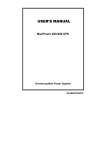
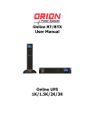
Table 3: Charging voltage for 4 types of battery Battery Battery 12V battery system 24V battery system Type Type Bulk Floating Bulk Voltage Floating Code Voltage Voltage Voltage Vented 01 14.3 V 13.2 V 28.6 V 26.4 V Sealed 02 14.3 V 13.4 V 28.6 V 26.8 V Gel 03 14.3 V 13.7 V 28.6 V 27.4 V NiCd 04 14.3 V 14.0 V 28.6 V 28.0 V Custom 05 Self-defined Self-defined Self-defined Self-defined Table 4: Alarm point for low battery voltage table Connected battery system Alarm point 12V 10.5 V 24V 21.0 V SCC-MPPT Solar Charge Controller Quick Guide Table 5: Charging hour table for reference Battery Capacity To 90% capacity @ 25A charging current 52 Ah 2 hours 100 Ah 4 hours 200 Ah 8 hours 300 Ah 12 hours 400 Ah 16 hours 500 Ah 20 hours Table 6: Power consumption of home appliances table* Appliances Power Consumption (W) 60 Daily usage hours Daily watt hours used (Wh) 360 Lighting bulb 6 Energy saving 13 6 78 bulb Electric fan 60 12 720 TV 100 4 400 Washing 800 1 800 machine Air conditioner 800 6 4800 Freezer 400 24 9600 PC with 17” 150 6 900 monitor Laptop 70 6 420 *This power consumption table may be different based on different consumer behavior and local electronic specifications. 11 SCC-MPPT 200W SCC-MPPT 300W SCC-MPPT 400W SCC-MPPT 600W V. 2.1 1. Introduction SCC-MPPT solar charge controller uses PWM-based DSP controller to keep the batteries regulated and prevent batteries from overcharging and discharging. Applying intelligent MPPT algorithm, it allows SCC-MPPT solar charge controller to extract maximum power from solar arrays by finding the maximum power point of the array. The solar charge controller facilitates a standalone energy system. Typical applications are listed below: Mobile applications such as moving van, lodge, log cabin, or night market. Lighting applications such as street lights, road lights, or garage lights. Remote village with power shortage 2. Installation Inspection Remove the unit from the shipping package and inspect it for damage that may occur during transportation. Notify the carrier and place of purchase if any damage is found. Installation Note 1. Product Overview Power switch Solar energy status indicator (Blue LED) Charging status indicator (Green LED) Site wiring fault indicator (Red/Orange/Yellow LED) LCD display (see Operation Section for the details) Terminal block for solar panel connection Terminal block for battery connection Terminal block for load connection Read all the installation section before beginning installation CAUTION! Careful to reduce the risk or dropping a metal tool on the batteries. It could spark or short circuit the batteries and could cause an explosion. CAUTION! Remove personal metal items such as rings, bracelets, necklaces, and watches when working with batteries. Batteries can produce a short circuit current high enough to make metal melt, and could cause severe burns. CAUTION! Avoid touching eyes while working near batteries. CAUTION! Have plenty of fresh water and soap nearby in case battery acid contacts skin, clothing, or eyes. Explosive battery gasses may be present during charging . be certain there is sufficient ventilation to release the gasses. CAUTION! NEVER smoke or allow a spark or flame in vicinity of a battery. Do not expose this charger controller to rain, snow or liquids of any type. WARNING! Provide ventilation to outdoors from the battery compartment. The battery enclosure should be designed to prevent accumulation and concentration of hydrogen gas at the top of the compartment. CAUTION! Use insulated tools to reduce the chance of short-circuit when installing or working with the inverter, the batteries, or other equipments attached to this unit. CAUTION! For battery installation and maintenance, read the battery manufacturer's installation and maintenance instructions prior to operating. Only charge Sealed Lead Acid, Vented Lead, NiCd or Gel batteries. CAUTION! To reduce risk of injury, only use qualified batteries from qualified distributors or manufacturers. Any unqualified batteries may cause damage and injury. Do NOT use old or overdue batteries. Please check the battery type and date code before installation to avoid damage and injury. WARNING! It's very important for safety and efficient operation to use appropriate external battery cable. To reduce risk of injury, external cables including battery cables, PV panel cables and load connected cables should be UL certified and rated for 75° C or higher. And strongly suggest not to use copper cables less than 12AWG. Below is the external battery cable reference according to system requirements. Model Nominal Battery Voltage Typical Current (Amp) SCC-MPPT-200W 12 V 17 A SCC-MPPT 300W 12 V 25 A SCC-MPPT-400W 12V or 24 V (auto sensing) 17 A SCC-MPPT 600W 12V or 24 V (auto sensing) 25 A NOTE: It's recommended to allow experienced personnel to install solar panel because the efficiency of solar energy transmission is directly effected by installation angles. Please follow the voltage requirement of the unit to wire connection with solar panel and batteries. 1 2 Wall Terminal Installation Step 1: Prepare flat screwdriver, supplied terminals and stripped wires. Chart 1 Step 2: Insert stripped wire into supplied terminal. Use crimping tool to press stripped wire and terminal in position. Refer to chart2. Fig. 1 Step 3: Screw assembled terminal and wire into solar charge controller. Refer to chart 3. Fig. 2 Chart 2 Chart 3 Fig. 3 Mounting Step 1: Choose mounting location Locate the solar charger controller on a vertical surface. Select an appropriate mounting location. Use a horizontal line and the length of the line must be 150mm and mark the two ends on the wall. (see Fig. 1 & Fig. 3) Step 2: Check the clearance Install the solar charge controller in a protected area that is free of excessive dust and has adequate air flow. Please place the solar charge controller away from other units at least 20 cm to avoid interference. Do NOT operate it where the temperature and humidity is outside the specific limits. (Please check the specs for the limitations.) Step 3: Drill the holes Remove the controller and drill 2 holes in the marked locations with 2 screws. Step 4: Secure controller Place the unit on the surface and align the mounting holes with 2 screws in step 3. (see Fig. 2 & Fig. 4) Fig. 4 Wiring CAUTION! Be sure to secure all wiring, especially for mobile applications. Use cable clamps to prevent cables from swaying when the vehicle is in motion. Unsecured cables create loose and resistive connections which may cause excessive heating or fire Step 1: DC Load Wiring The load output will provide battery voltage to connected loads such as lights, pumps, monitors and other electronic devices. Step 1: connect load positive (+) wire to the positive terminal of the unit and load negative (-) wire to the negative terminal of the unit. Step 2: install a DC Breaker or a DC fuse holder in a positive wire. The rating of the DC Breaker/Fuse must be according to the charging current (40 Amp). Keep the DC 3 4 breaker off or do not install the DC fuse. WARNING! Please use the appropriate cable size according to load rating. Please refer to Important Safety Warnings Section for the details. It will prevent internal high temperature. Step 2: Battery Wiring Step 1: connect battery positive (+) wire to the positive terminal of the unit and load negative (-) wire to the negative terminal of the unit. Step 2: install a DC Breaker or a DC fuse holder in a positive wire. The rating of the DC Breaker/Fuse must be according to the charging current (40 Amp). Keep the DC breaker off or do not install the DC fuse. 1) Multiple batteries in series connection (Refer to Fig. 5): All batteries must be equal in voltage and amp hour capacity. The sum of their voltages must be equal to the nominal DC Voltage of the unit. Fig. 5 Step 3: Solar Module Wiring WARNING: Risk of electric shock! Exercise caution when handing solar wiring. The solar array high voltage output can cause severe shock or injury. Cover modules from the sun before installing solar panel wiring. Step 1: connect positive (+) wire of solar module to the positive terminal of the unit and negative (-) wire of solar module to the negative terminal of the unit. 1) Single solar module connection (Refer to Fig. 7): When using a single solar module, its voltage must not exceed the maximum solar module open circuit voltage (see below Table 1). Fig. 7 Table 1: Model Solar Module Open Circuit Maximum Solar Module Voltage (max.) Power SCC-MPPT 200W 50 VDC 200 W SCC-MPPT 300W 50 VDC 300 W SCC-MPPT 400W 75 VDC@ 24 V or 50 VDC@ 12 V 400 W@24V or 200 W@12V SCC-MPPT 600W 75 VDC@ 24 V or 50 VDC@ 12 V 600 W@24V or 300 W@12V 2) Multiple solar modules in series connection (Refer to Fig. 8): All modules must be equal in voltage and amp hour capacity. The sum of their voltages must not exceed the maximum solar module open circuit voltage. And, the sum of their solar power must not exceed the maximum capacity of the unit. 2) Multiple batteries in parallel connection (Refer to Fig. 6): Each battery's voltage must be equal to the Nominal DC Voltage of the unit. Fig. 6 Fig. 8 3) Multiple solar modules in parallel connection (Refer to Fig. 9): Each module's voltage must not exceed the maximum solar module open circuit voltage. And, the sum of their solar power must not exceed the maximum capacity of the unit. 5 6 Status, LED/LCD Display and Audible Alarms Fig. 9 CAUTION: It may not cause any damage to solar module or unit when connecting polarity reversals. However, the unit will not be able to work normally. WARNING! Please use the appropriate cable. Please refer to Important Safety Warnings Section for the details. Step 4: Switch on DC breaker or install DC fuse After completing all wires, double check if all wires are connected well. Then switch on DC breaker or install DC fuse on. Take off the cover of solar module. When the voltage of solar module is 5VDC higher than battery voltage, the charger will automatically turn on to work. NOTE: If battery is not connected, even though solar module power is achieved, the charger is still not working. 3. Operation After all wires are connected, the solar charge controller will automatically be activated. At this time, the blue LED will light up and LCD display panel will show information. Switch Operation The switch has three modes during operation: Activate LCD backlight Press button for less than 1 second Select battery type* When the unit starts to work, press button for 1-3 seconds to select battery type. DI: vented battery D2: sealed lead acid battery D3: Gel battery D4: NiCd battery D5: Custom** Mute Press button > 3 seconds Power on Press button for 1 second to turn on the unit. *Please carefully to select battery type. It will damage battery if the setting is incorrect. Refer to charging voltage table in the appendix. **This option is self-defined bulk/floating voltage via bundled software. 7 Status Polarity reversal on solar module connection. Polarity reversal on battery connection. Polarity reversal on battery and solar module connection. Battery is in charging. Low battery voltage.* LCD LED Alarm N/A Yellow LED on. N/A N/A Red LED on. N/A N/A Orange LED on. N/A Blue & Green LEDs on. N/A. N/A Sounding every sec N/A Sounding every 2 secs. for 5 min. Then continuously sounding. Flashing every sec. 110% overload. Flashing every 2 secs. *Refer to alarm point for low voltage table in appendix. Fault and error codes table: Status LCD LED Battery defect. There is power input from solar module, but Green LED battery voltage is too low. on. 12V system: < 8.5V 24V system: < 17V Overcharge and the charger will Blue LED on automatically cut off output. 130% overload and the charger N/A will automatically cut off output. When solar input voltage is too Blue LED high, the charger will flashes every automatically cut off charging. second 8 Alarm Continuously sounding. Continuously sounding. Continuously sounding. N/A 4. Specifications Model SCC-MPPT 200W INPUT MPPT Range @ Operating Voltage Maximum Solar Module Open Circuit Voltage Maximum Solar Module Power Maximum Current OUTPUT Nominal Battery Voltage Connected Battery Type Maximum Charging Current Standby Power Consumption Charging Method PHYSICAL Dimension (DxWxH mm) Net Weight (kgs) ENVIRONMENT Humidity Operating Temperature Storage Temperature 5. Trouble Shooting Problem Yellow LED on Red LED on. Orange LED on. No solar energy input during daytime. F0 fault code displays on LCD panel Backup time is shorter. SCC-MPPT 300W 15 V ~ 37 V @ 12 V 50 V 200 W 300 W 12 A 18 A SCC-MPPT 400W SCC-MPPT 600W 30 V ~ 66 V @ 24 V 15 V ~ 33 V @ 12 V 75 V@ 24 V 50 V@ 12 V 400W@24V 600W@24V 200W@12V 300W@12V 12 A 18 A 12V 24V or 12V (auto sensing) Sealed lead acid, vented, Gel, NiCd battery 17 A 25 A 17 A 25 A 2W Three stages: bulk, absorption, and floating 135 x 170 x 57.5 0.92 220 x 170 x 57.5 1.85 0-100 % RH (non-condensing) -20°C - 55°C -40°C - 75°C Possible Cause Polarity reversal on solar module connection. Polarity reversal on battery connection. Polarity reversal on solar module and battery connection. Wires are not firmly connected. Solar module defect. Battery wires are not connected well. Battery defect. Battery defect. Overload. 9 Solutions Reconnect polarity again Reconnect polarity again. Reconnect polarity of solar module and battery again. Check if all wires are connected properly. Check solar modules or call local dealer to replace solar modules. Check if battery wires are properly connected. Replace battery. Check battery life cycle and replace battery. Remove excess loads. Problem F1 fault code displays on LCD panel. F2 fault code displays on LCD panel. E1 fault code displays on LCD panel. Possible Cause Battery wires are not connected well. Battery defect. Charge controller defect. Overload. Solutions Check if battery wires are properly connected. Replace battery. Replace the unit. Remove excess loads. Solar input voltage is too high. Check if solar wiring is correct. And then check solar input voltage. If there is any abnormal situations occur which doesn't list above, please call the service people immediately for professional examine. APPENDIX Table 1: Recommended minimum battery cable size versus length Model Nominal battery Charging 1 meter Dia-mm Voltage Current (one-way) SCC-MPPT 200W 12 V 17 A AWG 12 2.0525 SCC-MPPT 300W 12 V 25 A AWG 12 2.0525 SCC-MPPT 400W 24 V or 12 V 17 A AWG 12 2.0525 (auto sensing) SCC-MPPT 600W 25 A AWG 12 2.0525 Table 2 External Battery Cable Size Reference AWG (American Wire Gauge Size) 0000(4/0) 000(3/0) 00(2/0) 0(1/0) 1 2 3 4 5 6 7 8 9 10 11 12 Dia-mm (Diameter in millimeters) 11.684 10.405 9.2657 8.2513 7.348 6.5436 5.8272 5.1893 4.6212 4.1153 3.6648 3.2636 2.9063 2.5881 2.3048 2.0525 10 Ohms/Kft (Ohms per 1,000ft or 304.8 meter) 0.049 0.0618 0.0779 0.0983 0.1239 0.1563 0.197 0.2485 0.3133 0.3951 0.4982 0.6282 0.7921 0.9989 1.2596 1.5883