1
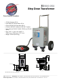
TI2000-054 Step Down Transformer Power Anytime, Anywhere • 15 kVA, 3-phase, 60 Hz. • Input 480 VAC 18 Amps Max. 60 Hz • Output 208 VAC 42 Amps Max. 60 Hz • Converts 480 VAC, 3-phase to 208 VAC, 3-phase. • Used with the TI4200, TI4400, TI5200 and TI5400 GPUs. • Size: 21.3” L x 24.5” W x 28.63” H 539.2 mm x 622.3 mm x 727.2 mm • Weight: 195 lbs 2(88.45 kg) 3 1 4 5 6 7 8 B C 23.04 [585.1] A 13.28 [337.4] A B C TOP VIEW 13.44 [341.3] 13.19 [335.0] 24.98 [634.6] 10.00 [254.0] 28.64 [727.3] D 18.13 [460.4] D E E 24.50 [622.3] SIDE VIEW FRONT VIEW F F * All dimensions are in inches [millimeters] 1 2 3 4 5 6 7 Tesla™ Industries, Inc. • Headquarters: (302) 324-8910 • 101 Centerpoint Blvd. New Castle, DE 19720 • Email: [email protected] Western Regional Office: (775) 622-8801 • 9475 Double R Blvd. Suite 2, Reno, NV 89521 USA • www.teslaind.com • 02-11-14 8 Power Anytime, Anywhere Tesla™ TI2000-054 Transformer User Manual Built Smart...Proven Tough Tesla Industries, Inc. 101 Centerpoint Blvd. New Castle, DE 19720 (302) 324-8910 Phone (302) 324-8912 Fax www.teslaind.com NOTE: All users must read this entire manual prior to operating the TI2000-054 Transformer. The TI2000-054 Step Down Transformer is a limited maintenance-free and sealed unit. No repairs are authorized. Warranty will be voided if unit is tampered with in any way, or if unauthorized repairs are made. For technical support please contact: TESLA™ INDUSTRIES INCORPORATED 101 CENTERPOINT BLVD. CENTERPOINT INDUSTRIAL PARK NEW CASTLE, DELAWARE 19720 PHONE: (302) 324-8910 FAX: (302) 324-8912 WEBSITE: www.teslaind.com EMAIL: [email protected] CAUTION Shock Hazard Potential Improper use or failure to follow instructions in this user manual can result in unit damage and/or injury or death by electrical shock. Any attempts to open or examine the inside of the TI2000-054 Step Down Transformer via a tool or device (borescope, probe, etc.) can result in unit failure and/or injury by electrical shock. Always protect the unit from short circuit. No part of this manual may be reproduced or transmitted in any form or by any means, electronic or mechanical, including photocopying, recording, or any information storage and retrieval system, without prior written permission from Tesla Industries, Inc. Copyright © 2014 by Tesla Industries, Incorporated. All rights reserved. 04-18-14 Table of Contents 4 Section 1 – Safety Review 1.1 – Safety Notices 1.2 – Symbols 1.3 – Hazards 1.4 – Important Safety Precautions 1.5 – Extreme Environments 1 1 1 2 2 2 Section 2 – Product Overview 2.1 – Introduction 2.2 – Use of Words: Shall, Should, May 2.3 – General Specifications 2.4 – Physical Dimensions 2.5 – Airflow Ports 2.6 – Features Overview 2.7 – 480 VAC Input 2.8 – 280 VAC Output 2.9 – Phase Indicator lights 2.10 – Fuses 1.11 – Transport Features 3 3 3 4 5 6 7 8 9 10 11 12-13 Section 4 – Pre-Operation 4.1 – Maintenance Checks 14 14 TI2000-054 Transformer Section 5 – Operating Procedures 5.1 – General 5.2 – Operating Limits and Restrictions 5.3 – Connect to VAC Power 5.4 – Connect Ground Power Unit to Transformer 5.5 – Connect DC Cable to Ground Power Unit 5.6 – Connect DC Cable to Aircraft 15 15 15 15 16 16 17 Section 6 – Post-Operating Procedures 6.1 – General 18 18 Section 7 – Unit Care and Maintenance 7.1 – Unit Care 7.2 – Normal Functional Test Procedures 19 19 20-21 Section 8 –Frequently Asked Questions 29-30 Repair Request Form 31 TI2000-054 Transformer 5 Abbreviations and Symbols Abbreviations and Symbols Abbreviations and are symbols used within text, headings titles. and Unless otherwise indicated,indicated, the following Abbreviations are used within text,and headings titles. Unless otherwise the list of abbreviations symbols areand used in thisare manual: following list ofand abbreviations symbols used in this manual: LIST OF ABBREVIATIONS LIST OF ABBREVIATIONS AND SYMBOLS Abbreviation Definition Amp Ampere AC Alternating Current °C Degree Celsius cont Continuous DC Direct Current °F Degree Fahrenheit Ft Feet FWD Forward GPU Ground Power Unit Hr Hour Hz Hertz Kg Kilograms KW Kilowatts LED Light Emitting Diode MAX Maximum MIN Minimum MPU Micro Power Unit VAC Volts, Alternating Current VDC Volts, Direct Current 6 TI2000-054 Transformer Section 1 – Safety Review 1.1 - Safety Notices Safety notices appear throughout this manual to alert the user to important information regarding proper installation, operation, maintenance and storage of the unit. These notices, as illustrated below, contain a key word that indicates the level of hazard and a triangular icon that indicates the specific type of hazard. ! WARNING Indicates a condition, operating procedure or practice, which if not adhered to could result in serious injury or death. ! CAUTION Indicates a condition or operating procedure, which if not strictly adhered to could result in damage or destruction of equipment. ! NOTE Indicates a condition, operating procedure or practice, which is essential to highlight. 1.2 - Symbols The following symbols will appear within the warning triangles to alert the user to the specific type of danger or hazard. ! General Warning Electrical Hazard Battery Warning Explosion Hazard Fire Hazard Guard from Moisture Figure 1.2.1 – Different types of hazard and caution symbols TI2000-054 Transformer 1 1.3 – Hazards WARNING Shock Hazard Potential Severe injury or death from electrical shock may occur if either the user or the unit is wet while the operating unit is connected to a power source. Be sure to disconnect AC power from the AC source if the unit has come into contact with water. If AC Input Circuit Breaker has tripped due to water infiltration, DO NOT try to reset it with the AC line voltage attached. WARNING Shock Hazard Potential Severe injury or death from electrical shock can occur when damp electrical plugs are connected to the unit. Make sure the unit is turned off before making any connections. Failure to use proper grounding can cause potential shock hazard! In different countries, the power cord may require the use of a plug adapter to achieve plug style compatibility for operation. Use only adapters with proper grounding mechanism. 1.4 – Important Safety Precautions WARNING Fire/Explosion Hazard Potential Severe injury or death from fire or explosion can occur if electrical sparks are produced near fuel vapors. DO NOT CONNECT AC Power Supply WHILE FUELING. AC power functions of unit shall not be operated during any fuelFigure handling Power outputFigure is restricted to DCGround power only. Figure 1.3.3 – Improper Ground 1.3.1operation. – Proper Ground 1.3.2 – Proper Grounded Plug with Grounding Pin 1.5 – Extreme Environments CAUTION CAUTION Adapter with Grounding Mechanism (Secured to Outlet) Plug with No Grounding Pin Unit Damage Potential Unit Damage Potential The unit is equipped with a charger temperature switch that automatically disables the unit when the internal The unit will be damaged if unapproved AC protects power isthe applied. Check temperature exceeds 150°F (65°C). This unit from overheating and damage. If the unit shuts the Input Voltage Selector (outlined in blue) to ensure down, move the unit into aSwitch coolerwindow environment such as shade or air conditioning when possible. Perform a the function switch setting (115V or 230V) matches thetoAC power full test after the unit has been allowed cool priorsource to use. (hangar wall, flight line AC power) prior to connecting the unit for recharging. NOTE: This Transformer is for Indoor use only. 2 TI2000-054 Transformer Section 2 – Product Overview 2.1 – Introduction This manual contains the complete operating instructions and procedures for the TI2000-054 Transformer. The TI2000-054 Transformer is intended for converting 480 three phase VAC to 208 three phase VAC. This manual makes specific reference to the TI2000-054 Transformer being used as an accessory providing 208 three phase VAC to Tesla Industries Ground Power Units. The observance of procedures, limitations and performance criteria is essential to ensure peak operating efficiency and to maximize operational capabilities and life of the TI2000-054 Transformer. Figure 2.1.1 – TI2000-054 Transformer 2.2 – Use of Words Shall, Should and May Within this technical manual the word “shall” is used to indicate a mandatory requirement for proper operation and warranty purposes. The word “should” is used to indicate a non-mandatory but preferred method of accomplishment. The word “may” is used to indicate an acceptable method of accomplishment. TI2000-054 Transformer 3 2 Product Overview 2.3 – General Specifications Electrical Input Power: • • • • • • • 480 VAC / 18 Amps 3ø 50 / 60Hz 15 KVA 18 Amps Class 220°C 150°C Temperature Rise Delta Output: Power • • • • • 208 VAC 3ø 50 / 60Hz 15 KVA 42 Amps Wye Size: • 22” long x 25” wide x 25” high • 558.80mm x 635mm x 635mm Weight • 195 lbs (88.45kg) 4 TI2000-054 Transformer Product Overview 2 2.4 – Physical Dimensions Figure 2.4.1 – TI2000-054 physical dimensions TI2000-054 Transformer 5 2 Product Overview 2.5 – Airflow Ports CAUTION Damage may occur if the TI2000-054 Transformer’s air intake or outlet ports are obstructed. Ensure that ports are clear at all times. The TI2000-054 is intended for indoor use only. If outdoor use is necessary, contact Tesla for a sealed weather-proof cover. Make sure the airflow is not obstructed and air vents are clear. Do not allow foreign objects, blowing sand or dust to enter the air vents. Do not allow the unit to be exposed to precipitation or excessive moisture. Figure 2.5.1 – Air intake and exhaust ports and internal air circulation 6 TI2000-054 Transformer Product Overview 2 2.6 – Features Overview The TI2000-054 is designed to convert 480 three phase VAC to 208 three phase VAC. The unit’s exterior features an input receptacle, an output receptacle, phase indicator lights, and a telescopic handle and wheels for transport. The inside of the unit features replaceable fuses. 5 4 3 2 1 1. Locking Casters and Run-flat tires. 2. 480 Three Phase Input 3. 208 Three Phase Output 4. A, B and C Phase Indicator Lights 5. Telescopic Handle TI2000-054 Transformer 7 2 Product Overview 2.7 – 480 VAC Input The 480 Three Phase VAC input cable is twenty feet long with a plug. Figure 4.2.1 480 VAC Input cable location ! CAUTION Unit may be damaged if incorrect AC power is applied. Check to make sure the unit is plugged into 480 phase VAC. Figure 4.2.2 480 VAC cable plugged in. 8 TI2000-054 Transformer Product Overview 2 2.8 – 280 VAC Output The TI2000-054 has a 208 three phase VAC output located on the front of the unit. The output is a female receptacle and is used for plugging in the TI5400 GHMD male plug. Figure 4.3.1 208 VAC Input cable location Figure 4.3.2 208 VAC receptacle. TI2000-054 Transformer Figure 4.3.3 208 VAC cable plugged in. 9 2 Product Overview 2.9 – Phase Indicator Lights The Phase indicator lights indicate that each phase is live. All three lights should activate when the unit is plugged into the AC power source. If all three lights do not activate then there is a problem with the AC power source. Disconnect the unit and troubleshoot the power source. Figure 2.9.1 Phase Indicator Lights location Figure 2.9.2 Indicator Lights OFF. 10 Figure 2.9.3 Indicators Lights ON. TI2000-054 Transformer Product Overview 2 2.10 – Fuses To protect the unit from damage there are three fuses inside the unit. In order to replace the fuses the unit must be opened. The TI2000-054 has a three 30A 600V fuses located on the backside of the front panel. Check with multimeter to ensure the fuses are blown before replacing. ! CAUTION Be sure unit is completely disconnected from power before opening unit. NOTE: This is the only repair authorized for the user. For all other repairs please contact Tesla™ Customer Service at (302) 324-8910 with any questions or concerns. Figure 2.10.1 Replaceable Fuses TI2000-054 Transformer 11 2 Product Overview 2.11 – Transporting Unit The TI2000-054 has a telescopic handle that makes it easy to roll or push the unit. It is also equipped with four wheels. Telescopic Handle Wheels Figure 4.6.1 Telescopic Handle and Wheel Locations Lockable Casters and Run-flat Tires. The Transformer is equipped with two ten inch run-flat tires and two lockable casters. The transformer can be maneuvered on all four or tilted with the handle onto the rear tires for transport. Figure 2.11.2 Lockable Casters. 12 Figure 2.11.3 10 inch run-flat tires. TI2000-054 Transformer Product Overview 2 Telescopic Handle. The Transformer has a telescoping handle that makes rolling the unit easy. 1. Handle in down position. 2. Loosen knobs by turning counter clockwise. 3. Handle in up position. 4. Tighten knobs by turning counter clockwise. TI2000-054 Transformer 13 Section 4 - Pre-Operation 4.1 –Maintenance Check Before operating the TI2000-054 check for any signs of damage or wear to the unit, tires, cables and plugs. Check Unit Check the unit for dents, punctures, case distortion or mis-alignment, cracked or loose connectors. If no external damage is evident user may proceed. If damage is evident contact Tesla Industries. Check Tires The TI2000-054 is equipped with solid Run-Flat tires. No air is required. However, if the tires are damaged they can be easily replaced. Check DC Power Cable And AC Power Cord For Damage Crushed or torn cables will need to be replaced, before any operations can occur. Check DC Power Cable/Connections For Damage Check connectors for cracks, cuts, distortions, excessive wear, broken/loose fasteners and cable attachment. Replace contacts or entire plug if necessary. 14 TI2000-054 Transformer Section 5 - Operating Procedures 5.1 – General This section defines the operating procedures, which includes all steps necessary to ensure safe and efficient operation. Correct operation of the TI2000-054 includes both pre-use and operational checks of the unit. Knowledge of the operating limits, restrictions, performance, unit capabilities and functions is fundamental to correct and safe operation. The operator shall ensure compliance with the instructions in this manual that affect operational safety and the warranty of the unit. 5.2 – Operating Limits and Restrictions The minimum, maximum and normal operating ranges result from careful engineering and evaluation of test data. These limitations must be adhered to during all phases of operation. WARNING Fire/Explosion Hazard Potential Severe injury or death from fire or explosion can occur if electrical sparks are produced near fuel vapors. To prevent this, make sure electrical outlets are switched to “OFF” position before connecting electrical plugs. For added safety, this unit shall not be operated during any aircraft fuel handling operation. 5.3 – Connect to VAC Power Plug the transformers VAC input plug into the appropriate 480 three phase VAC outlet. All three phase lights will come on. If all three lights do not activate then there is a problem with the AC power source. Disconnect the unit and troubleshoot the power source. ! CAUTION Unit may be damaged if incorrect AC power is applied. The transformer must be plugged into a 480 three phase VAC power source. Figure 6.3.1 Transformer connected to VAC Power TI2000-054 Transformer 15 5 Operating Procedures 5.4 – Connect Ground Power Unit to Transformer ! CAUTION NOTE: Before plugging the unit into the Transformer switch the GPU’s input power circuit breaker to the “OFF” position. The TI5400 400HZ GHMD can then be plugged into the transformer’s output socket. Once the plug is securely in place, the input power circuit breaker can be switched to the “ON” position. Figure 5.4.1 Transformer connected to GPU 5.5 – Connect DC Cable to Ground Power Unit The chances of accidental arching are low, but for added safety, press the DC Output “OFF” button. Ensure power cable connector is fully seated into the DC output receptacle. Figure 5.5.1 DC “ON/OFF” buttons location. Figure 5.5.2 DC “ON/OFF” buttons. Figure 5.5.3 DC cable plugged into GPU. 16 TI2000-054 Transformer Operating Procedures 5 5.6 – Connect DC Cable to Aircraft To prevent arching while connecting DC power to the aircraft, press the DC output “OFF” button, then connect DC power to the vehicle. Ensure ground power cable connector is fully seated into aircraft receptacle. When you are ready to supply DC power, press the DC output “ON” button and it will illuminate. DC bus power should come on and the aircraft’s voltmeter should indicate 23.5 to 24 VDC (23 VDC minimum). Starting Aircraft Engine Check power cable for security and correct installation prior to engine start. Follow ground power unit engine starting procedure as specified in aircraft operator’s manual. Figure 5.6.1 Connecting DC cable to aircraft and starting engine TI2000-054 Transformer 17 Section 6 - Post-Operating Procedures 6.1 – General When not in use, the TI2000-054 Transformer should be covered and stored in a dry, temperature controlled area. Protect the unit from the elements and man-made hazards whenever possible. Make sure to keep the transformer’s receptacle, plugs and air vents clear of debris. Disconnect unit and allow cooling time. 18 TI2000-054 Transformer Section 7 5 -–Unit UnitCare Careand andMaintenance Maintenance WARNING Severe injury or death from electrical shock may occur if either the user or the unit is wet while operating the unit with an AC power source attached. CAUTION Damage may occur if an unapproved or modified AC line cable or input plug is attached to the unit. Do not use any type of AC voltage converter. 5.1 –- Unit 7.1 UnitCare care Avoid Prolonged Exposure to Extremely Damp Environments Be sure to disconnect AC power from the AC source if the unit has come into contact with water. If the AC Input Circuit Breaker has tripped due to water infiltration, allow the unit to dry out before attempting to reset circuit breaker. Cover the unit to prevent water seepage. If the unit is operated in extremely damp conditions, it should be stored in an environmentally controlled building when not in use. Wipe unit clean periodically with a soft cloth to remove dust, dirt, etc. Protect Cables from Damage Do not cut, crush, or drag the input or output power cables when handling the unit. Always inspect cables prior to use. If no damage is evident, proceed to the next step. If damage is evident, contact Tesla™ Customer Service. Do not attempt to use any other type of power cables other than the Tesla™ cables included with the unit. Figure 5.1.1 – Damaged cable TI2000-054 Transformer 19 7 Unit Care and Maintenance 7.2 – Normal Function Test Procedures This section deals with “normal function” test procedures, and includes all steps necessary to ensure that the TI2000-054 is operating within specified parameters prior to use. A digital multimeter (an example is shown in Figure 8.2.1) capable of measuring DC and AC voltage and resistance will be required to perform some of the tests. These functional test procedures should become routine. Figure 8.2.1 – Digital Multimeter Check Unit for Evidence of Damage Check for dents, punctures, case distortion or misalignment, and cracked or loose connectors. If no damage is evident, proceed to the next step. If damage is evident, contact Tesla™ Industries, Inc. Figure 8.2.2 – Damaged Unit Misaligned Case with Bent Faceplate 20 TI2000-054 Transformer Unit Care and Maintenance 7 Check Unit Internal Resistance (Test for Shorts) This section deals with “normal function” test procedures, and includes all steps necessary to ensure that the transformer is operating within specified parameters prior to use. A digital multimeter (an example is shown in Figure 8.2.1) capable of measuring DC and AC voltage and resistance will be required to perform some of the tests. These functional test procedures should become routine. Check Unit Approximately 120 VAC 1. Place the negative probe on the receptacle’s left ground insert and the positive probe on top side phase 1 insert. 2. Move the positive probe to the right side phase 2 positive insert. 3. Move the positive probe to the lower phase 3 positive post. 2. Move the positive probe to the lower phase 3 positive post. 3. Move the negative probe to the right side phase 2 probe and the positive probe to lower phase 3 probe. Check Unit Approximately 208 VAC 1. Move the negative probe to the upper phase 1 probe and the positive probe to right side phase 2 probe. TI2000-054 Transformer 21 Section 8 6 – Frequently Troubleshooting Askedand Questions FAQ 6.1 – Frequently Asked Questions 1. Why should I buy a Tesla™ Turbo Start™ System? Tesla™ Turbo Start™ is a multi-functional system that are ideal for support of 24 VDC vehicles and aircraft and their electronics/avionics on the bench. Tesla™ manufactures various systems of different sizes and capacities that are manportable, maintenance free and provide pure, DC power in a completely safe package. Designed for Military applications, these systems are equally valuable in maintenance support at the main facility or in remote locations. They are easily transported and air-portable. They will also provide 28.5 VDC when the system is connected to the appropriate AC source. 2. How does a Turbo Start™ work? The Turbo Start™ combines state of the art power conversion electronics with our proprietary “dry cell” batteries. The system’s electronics incorporate an intelligent charging system for the cells. The cells are ideal for this application as they are non-spillable, absorbed electrolyte dry cells that are sealed, maintenance free and safe for air transport. 3. How is Turbo Start™ used in Aviation Support? There are many ways a Turbo Start™ will benefit your operation. By using it for pre-flight testing, you will avoid depleting the aircraft’s battery. You can start the aircraft’s engine with the Turbo Start™ as well. In the hangar, when connected to AC power, the Turbo Start™ will provide 28.5 VDC for avionics testing and will also recondition and recharge the aircraft’s battery. Another benefit is the ability to fly with the Turbo Start™ aboard your aircraft. You may take the Turbo Start™ anywhere you travel, ensuring that you will always have power. 4. How much power will my Turbo Start™ provide? Depending on the system, the Turbo Start™ will provide anywhere from 1500 to 3500 peak starting amps, 25 to 400 continuous amps DC and 23 to 96 hours of rechargeable power. See our website (www.teslaind.com) to determine the proper Turbo Start™ for your needs. 5. Will a Tesla™ Turbo Start™ spool up a turbine engine? Nothing will start a turbine engine faster or safer than the right Tesla™ Turbo Start™. Not only will it eliminate hot starts, but it will extend the life of your starter, your engine and your battery while reducing maintenance. The Turbo Start™ senses the impedance from the starter/generator. It then provides the exact power required throughout the start-up curve. 6. How many engine starts will my Turbo Start™ provide until it is depleted? The Turbo Start™ back-charges, almost instantly, once the vehicle / aircraft is started and the generator is on line. This “power flywheel” feature enables the Turbo Start™ to recharge itself right from the vehicle it started in less than 30 seconds. You can go down the line in your motor pool and start every 24V vehicle, without limit! 7. How do you prolong the life of the Turbo Start’s cells? All you need to do is plug the unit in to the appropriate AC power outlet the system requires. AC power will recharge the system and keep the cells healthy. Users who regularly plug the system in can expect to get 5-7 years from their cells before they need to be replaced. Tesla™ cells do not have a memory like cell phone batteries. There is no need to fully discharge them. The recharging system will not overcharge the unit or produce excess heat. 8. Is it waterproof? Water-resistant but not waterproof (See Environmental Section). 22 TI2000-054 Transformer Frequently Asked Questions 8 9. Are Tesla™ GPUs used in shop maintenance and testing? Tesla™ systems are gaining popularity throughout maintenance facilities, instructional facilities, laboratories, manufacturing plants, aircraft hangars and many other locations. The reason is due to the precise DC power, the small, portable and quiet nature of our systems and the maintenance free aspect of our GPU’s. We can custom tailor ground power systems to fit your individual requirements. 10. Can one person transport it? Turbo Start™ is designed to be handled by one person. The TI500 is our smallest GPU system to date and weighs 36 lbs. The TI1000 weighs 57 Lbs and can be carried or wheeled on a dolly. Larger units have wheels incorporated directly on the system with an extendable handle. 11. Is the Turbo Start™ in the government purchasing system? Yes. Tesla™ Industries is an approved vendor/supplier – our cage code is OVWE2. Most Tesla™ products are class IX, have a NSN (National Stock Number) designation and can be acquired through the DLA (Defense Logistics Agency). 12. How long does this unit stay charged? Unit should never be allowed to discharge fully. In-field use, it receives a DC back charge directly from a running engine. When not in use, unit should be plugged into AC power (outlet) all the time. Tesla™ systems will retain 80% of their capacity after one year of storage. 13. How do I get my Turbo Start™ serviced? Contact Tesla™. We can be reached at (302) 324-8910. Ask for customer service. You can also email us at [email protected]. Once we receive the unit at our facility, we will examine it. Systems that are protected under warranty will be repaired at no charge. If the warranty has expired, you will receive a quote for necessary repairs prior to work being done. Our turnaround time is 48 hours once repairs are authorized. 14. Can I make my own repairs to unit? During the warranty period, the unit can only be repaired by Tesla™ Industries for the warranty to remain in effect Regardless, we strongly recommend allowing Tesla™ to repair any unit as we will analyze the complete system and recalibrate it. 15. What type of maintenance does the Turbo Start™ require? Although the systems are maintenance free, please keep units plugged in while not in use. This will greatly extend the life of the cells. Also, keep the vent areas clean and free of debris. Keep units in a well ventilated area while charging. Keep the unit in a protected environment when not in use (maintenance facility, shed, etc.). 16. What is included with my Turbo Start™? Aviation customers will receive an eight (8’) foot DC Aviation Cable Assembly (TI2007-208). Ground vehicle customers will receive a fifteen (15’) foot DC NATO Cable Assembly (TI2007-315). All customers receive an AC line cord for their home country and a full two year warranty. 17. Are there any HAZMAT issues or disposability problems? There are none. Tesla™ will reclaim all battery cells for disposability purposes. Contact Tesla™ if you have questions. TI2000-054 Transformer 23 Repair Request Form Please complete the information below to ensure prompt and accurate service. Include this form with the unit you are returning. Thank you. Date of return: ________________________ Company name & ____________________________________________________________________ ____________________________________________________________________ ____________________________________________________________________ Billing address: ____________________________________________________________________ ____________________________________________________________________ ____________________________________________________________________ Contact person: ________________________________________________________________________________ Phone #: _____________________________________ Email: _______________________________________________________________________________________ Purchase Order #: Fax #: ______________________________________ ______________________________________________________________________________ Model #: ____________________________________ Serial #: ________________________________________ Model #: ____________________________________ Serial #: ________________________________________ Shipping method to Tesla™: ______________________________________________________________________ Description of shipping package: Description of problem: ________________________________________________________________ _________________________________________________________________________ _________________________________________________________________________________________________ _________________________________________________________________________________________________ _________________________________________________________________________________________________ Return to Tesla™ Industries, Inc. 101 Centerpoint Boulevard, New Castle, DE 19720 Attention: Repair Department 24 TI2000-054 Transformer