1
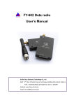
Low Power Wireless Module
User’s Manual
Before using the product, please read the user’s manual carefully. Any question in technical, you can
contact us.
About
, the Low power wireless module, is used as the wireless data transmission in short distance.
With the small size, weight and power consumption and good stability and reliability, it has the function
of bi-directional data sign transmission, test and control.
It is used for Wireless meter reading, such as water meter, electric meter and gas meter, parking meter,
intellective card, electronic weighing apparatus, meter for checking on work attendance, queue wireless meter,
building control, shipping company control, alarm system, intelligent equipment, Automatic data collecting
system; Industrial remote control and remote test building automation, safety and security, powerhouse
equipment wireless monitor, entrance control system, etc. It provide the USB power interface to be convenient
for the mini computer and PC users if necessary.
Mini Power Wireless Module User’s Manual
Feature
1.Ultra low power transmission
Transmission power :500mW,
high receiving sensitivity: -123dbm , size: 58mm*38mm*10 mm.
2. Low power consumption
Receiving current<45mA,transmission current<360mA,sleeping current < 1mA.
3. Saving power model
have three saving power models: awaken from Hardware, awaken from COM Port, awaken from air (the
user need to ask for it before place an order).
4.IO attemper function
have 2 on-off input ports, 2 on-off output ports.
5. ISM frequency band, not requiring on application of frequency point
Carrier frequency of 433MHz,also capable of 868/915MHz.
6. High anti-interference and low BER (Bit error Rate)
Based on the GFSK modulation mode, it adopts the efficient communication protocol. The actual bit error
rate of 10-5 ~ 10-6 can be achieved when channel bit error rate is 10-2.
7. Long transmission distance
Within the range of visibility, the reliable transmission distance is(BER=10-3/1200bps) >3000m when the
antenna height is greater than 2000m (BER=10-3/9600bps).
8. Transparent data transmission
Transparent data interface is offered to suit any standard or nonstandard user protocol. Any false data
generated in the air can be filtrated automatically (What has been received is exactly what has been
transmitted). The charge time for receiving and sending <10ms.
9. Multi-channel and speed
The standard configuration provides 16 channels. to meet the multiple communication combination
mode of the users. It has baud rate to be chosen such as 1200bps、2400bps、4800bps、9600bps、19200bps、
38400bps. The wireless transmission rate is direct ratio with baud rate of interface to meet user’s equipment
requirement.
10. High speed wireless communication and large data buffer
When the speed rate in the air is quicker than interface’s, allowing to transmit unlimited length data at one
time, when the speed rate is slower or equal the interface’s, allowing the transmission of 255 Bytes long data
frames at one time for more flexible programming by users.
11. Intelligent data control and the user doesn’t need to prepare excessive programs
Even for semi duplex communication, the user doesn’t need to prepare excessive programs, only
receiving/transmitting the data from the interface.
will automatically complete the other operations, such as
transmission/receiving conversion in the air, control, etc.
12. High reliability, small and light
Single chip radio- frequency integrated circuit and single chip MCU are used for lessened peripheral
circuits, high reliability, and low failure rate.
13. Watchdog monitor
Watchdog monitors the inner function, so that change the traditional product structure and improve the
product reliability.
1
Mini Power Wireless Module User’s Manual
Application of
1.Appearance figure
TX/RX indicator light
Antenna socket
Red: TX , Green :RX
User interface
figure
2.
interface definition
1) User’s interface
have one interface of TTL/RS232/RS485, user can choose one .
standard interface: when the antenna upward , the plastic socket gap upward ,from left to right,1-9
pin in turn,as below figure:
(Remarks: Jack space between is 2.0 mm.)
Definition of connecting pins and connection method:
Item no
PIN
Description Level Connected
User terminal
Remarks
to the terminal
1
SLE
Sleep control (input) end
Low level to sleep, High
level awake
2
TXD/ A (RS-485)
Serial data transmitting end
RXD/ A (RS-485)
3
RXD/ B (RS-485)
Serial data receiving end
TXD/ B (RS-485)
4
GND
Power supply/Ground
DGND/AGND
5
VCC
+5±0.5V
+5±0.5V
TTL 3V user’s choose
2
Mini Power Wireless Module User’s Manual
6
I2
NO. 2 on-off input
user terminal on-off output
7
I1
NO. 1 on-off input
user terminal on-off output
8
O2
NO. 2 on-off output
user terminal on-off input
9
O1
NO. 1 on-off output
user terminal on-off input
User’s equipment
+5v regulator n. power supply
transmitter-receiver
Remarks:
To avoid to connect the interface reverse and can not communicate, please check and assure the voltage of 2
and 3 pin is existing by using Multimeter. If there is one pin that has the voltage, another has not voltage,
which means the interface is connected reverse, please change the connection wires between pin 2 and 3.
2) Power supply
uses DC power supply with voltage of +5V. It can also share power supply with other equipment,
however, the high quality power supply with desirable ripple factor should be selected. In addition, the reliable
grounding must be used if there is other device in the system equipment. In case of failure to connect with the
earth, it can form its own grounding, but it must be absolutely separated from the municipal electric supply.
3) Application of IO control
have 2 on-off input ports,2 on-off output ports , you can use as follow:
on-off Output
User
terminal
on-off
output app circuit
3
Mini Power Wireless Module User’s Manual
on-off Input
User terminal on-off output
Input app circuit
3.Saving power model
have three Saving power models: awaken from Hardware, awaken from COM Port, awaken from Air.
The model can be set by RF Module software. You can choose one saving power model, the default model is
awaken from Hardware.
1) Awaken from Hardware:
When sleeping in this saving power model, the current is under 100uA.
Sleeping status: when you input low level at NO. 5 pin,
can sleep. In this status,
cannot transmit and
receive data.
Normal work status: when you input High level at NO. 5 pin,
turn into Normal work status, 10ms later,
can transmit and receive data.
Remarks: if you keep the NO. 5 pin untouched, then in Normal work status.
2) Awaken from COM Port:
When sleeping in this saving power model, the current is under 11mA. When you input data to with
COM port, turn into Normal work status after 10mS and can transmit the data. When did not receive
data in COM port in the period of 20 seconds,
will turn into sleep status.
3) Awaken from Air:
When sleeping in this saving power model, the current is under 20mA. When in this saving power
status,
works intermittently. When
received awaken data from air,
will turn into normal work status
after 10ms, it can receive data normally. When
did not receive data from air in the period of 20 seconds, it
will turn into sleep. So when you wake up from air, you can transmit some useless data firstly.
4、
、IO Attemper Function
have two communicate protocol: full transparence protocol and ID protocol.
(Remark: full transparence protocol is default protocol, if you need
with ID protocol, please tell us when
you book )
1) Full transparence protocol
In this mode, whatever you use, any data frame,
can send it to another side as like as two peas, it cannot
change data format and data bits.
with this transmit mode be used for Reading meter, RTU and PLC with
Address itself and so on.
2) ID protocol
When your terminal without Address or ID, you can use
with ID protocol , in this way you can
differentiate the data from you terminal. The Main station you must use with full transparence protocol, the
appurtenant station you must use with ID protocol. The of the appurtenant station must set ID according
4
Mini Power Wireless Module User’s Manual
our RF module software, you can resolve the data from user terminal transmit according to ID Protocol.
Remark: when you use with ID protocol, we provide 《communication protocol of 》 and programme
manual.
3) IO attemper function
You can use one with full transparence protocol for the Main station, some with ID protocol for the
appurtenant stations, each of the appurtenant station must set one unrepeatable ID. You can attemper the
appurtenant station IO according to communication protocol of .
Remark: when you use IO attemper function, we provide 《communication protocol of 》 and programme
manual.
parameters setting
have one interface of TTL、RS232、RS485, You must specify the interface when you buy.
main
parameters: COM baud rate and verify,RF baud rate, Channel and frequency。You can change these
parameters by our RF Module soft. When RF baud rate is faster than COM baud rate,One frame Can transmit
limitless data. When RF baud rate is not faster than COM baud rate ,One frame Can transmit 255 bytes most.
You can set the rate according your need. The general Power supply is 5V DC.
Two communicate must have condition as follow:
1.Their channels (i.e. frequency) are the same.
2.Their RF rates are the same.
3.RF Module Com baud rate and verify is agree with its equipment or PC that it connects with.
Parameters default value:
Channel: 1
Interface speed rate:9600BPS
Interface verify:none
Speed rate in air:9600BPS
Channel and frequency list
868MHZ
16 channel
Technical specification of
Modulation mode: GFSK
Working frequency:
866MHZ
Transmission power:
<500mW
Receiving sensitivity: -123dBm
Transmitting current:: <360mA
Receiving current: <45mA
Sleeping current: <1mA
Channel speed rate:
1200/2400/4800/9600/19200/38400Bit/s, User can Choose one
5
Mini Power Wireless Module User’s Manual
Interface speed rate:
1200/2400/4800/9600/19200/38400Bit/s, User can Choose one
Change time for receiving and sending: <10ms
Interface data format: 8E1/8N1/8O1
Power supply: 5±0.5V DC
Working temperature: -20℃~85℃
Working humidity:
10%~90% relative humidity without condensation
Dimension: 58mm*38mm*10 mm
Model and name
-T
T: TTL interface
2: 232 interface
4: 485 interface
Naked board
Optional Antenna:
Trouble and solve ways:
NO.
Trouble
Trouble causes and solve ways
1
No shine of
Indicator light
a、Power Line badness touch .
b、Power is bad.
c、Power line meet in reverse, or diode of polarity protect is bad.
2
No transmit or
No receive
a、Radio is badness touch with PC/terminal.
b、Radio with TTL/RS232/RS485 not match terminal.
c、RX frequency and TX frequency is not same.
6
Mini Power Wireless Module User’s Manual
3
Bit error
High
rate
4
Indicator
twinkling
light
a、antenna not match, or touch bad;
b、RF baud rate is not right.
c、Power supply ripple is too great.
a、Electromagnetism disturb in circumstance.
b、Same frequency disturb in the circumstance.
7