1
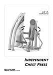
A915
OWNER'S MANUAL
ASSEMBLY INSTRUCTIONS
INDEPENDENT
CHEST PRESS
A. SAFETY INSTRUCTIONS
˙ Read all cautions/warnings and obtain proper instruction on use of the machines
prior to using. Use appropriate positioning and controlled movements.
˙ Assemble and operate the strength on a solid, level surface. Do not use outdoors
or near water.
˙ Never allow children on or near the strength.
˙ Make sure all fasteners are properly tightened for safety. DO NOT use the
strength if the unit is disassembled in any way.
˙ Keep head, limbs, and fingers clear of all moving parts.
˙ If at any time during exercise you feel faint, dizzy or experience pain, stop and
consult you physician.
˙ DO NOT wear loose or dangling clothing while using the equipment. Keep away
from all moving parts.
˙ Use care when mounting and dismounting the unit.
˙ DO NOT use any accessories that aren't specifically recommended by the
manufacturer. These might cause injuries or cause the unit to fall.
˙ Close supervision is necessary when this strength is used by, on, or near
adolescent, invalids, and disabled persons.
˙ Use this strength only for its intended use as described in this manual.
˙ Never operate this strength if it has been damaged in any way. If it is not working
properly, been dropped or damaged, contact your dealer. DO NOT attempt to fix a
broken or jammed machine. Notify floor staff.
˙ Never drop or insert any object into any opening.
1
B. Introduction
Side frame
Badge, rear
Badge, front
Front cover (B)
Right grip
Usage sticker
Back cushion
Rear cover
Left grip
Seat cushion and
seat cushion
adjustment handle
Cord
Stack fork
Hydraulic shock
Pedal push
rod assembly
Pedal push rod
assembly-right
Front cover (A)
Foot pad
Pedal push rod
assembly-left
Support frame
Foot pad
2
C. List of Parts
1. One side frame.
2. One support frame
3. One pedal push rod assy
4. One pedal push rod
5. One grip
6. Four hex socket head bolts M8 x P1.25 x L30, for the pedal push rod assembly and
pedal pushing rod (right and left)
7. Four spring washers, M8, for the pedal pushing rod assembly and pedal push rod
(right and left)
8. Four flat washers D17 x d8.3 x t2 for foot rest
9. Two hex socket head bolts, M8 x P1.25 x L20, for the pedal push rod and grip
10. Two wave washer, (WN6203) for the pedal push rod and grip
11. One bearing washer for the grip
12. One washer for the pedal push rod
13. One double-end open wrench,17mm x 23mm
14. One double-end open wrench, 8mm x 17mm
15. One hex key wrench, M6
16. One hex key wrench, M5
17. User's manual
18. One double-end open wrench, 8mm x 10mm
19. One double-end open wrench, 12mm x 15mm
20. One storage tray
3
D. STEP BY STEP INSTRUCTION:
1. Tighten the pedal pushing rod with screws as shown in Fig.1.
Fig.1
2. Tighten the grip with screws as shown in Fig.2.
Fig.2
4
3. Tighten the pedal push assembly and both left and right push rods together with
screws as shown in Fig. 3.
Fig.3
4. Assemble the belt and secure the screws tightly as shown in Fig. 4.
Fig.4
5
5. Please check the machine to see if both sides are level after assembly. Padding
either post with cardboard or wood plank to make both sides at the same level.
Then check the tightness of inserting the stack fork.
Note: If you feel too tight or too loose when you insert the stack fork between the
weight stacks, it means the machine is not level so padding the post with
the stuff is required.
Fig.5
6
E. BELT ADJUSTMENT:
1. If the belt is too tight or too loose, first loosen nut A as shown then adjust nut B. If
the belt length is too long, adjust downward; if the belt length is too short, adjust
upward. Adjust the belt to the proper position, then tighten nut A.
2. The gap between nut A and B must be within 35mm(1.4"). If the gap still
exceeds the 35mm limit after the first step, please loosen the screws on C
and adjust the belt to the proper length. Tighten the screws and follow the
1st step again. (See Fig. 6)
Fig.6
7
F. HOW TO USE THE MINOR WEIGHT STACK
1. To adjust the minor weight stack, insert the upper pin to add 3.5Lbs/1.5kgs
or the lower pin to add 6.5Lbs/3kgs.
2. Pull the pin to release the weight. (See Fig. 7)
3.5Lbs/1.5kgs
6.5Lbs/3kgs
Fig.7
8
G. STORAGE TRAY ASSEMBLY
Applicable strength products include that these products have the frame as following
shape.
Step 1:
Remove the existing screw and washer from
tubing.
Step 2:
Place storage tray onto tubing and tighten with the.
screw and washer that you just removed from step.
9
H. Maintenance Information
1. Lubricate guide rods every four months as follows.
(a) Place silicone lubricant on a clean, dry, lint-free cloth. Wipe guide rods thoroughly.
(B) Operate the unit and inspect for smoothness.
(c) Repeat steps (a) and (b) 2~3 times.
2. Inspect cable and belt tightness. Adjust cables and belts as necessary according to
instructions in owner manuals.
10
I. Important Safety Information
1. We recommend replacing belts once a year.
2. For safety, after one year of use, inspect the following at least once a month: A. the
belt area; B. the belt fibers. In particular, inspect for cracks in the belt and for
exposed fibers or other abnormalities. If you find any abnormality, stop usage
immediately and replace the belt. Note: more frequent inspections may be needed
in some cases.
11
Usage Instruction:
12
J. MAINTENANCE SCHEDULE
(A915) Maintenance Schedule
Clean.
1
Unit exterior
2
Screws
Inspect for looseness.
Tighten if necessary.
3
Cushions
Wipe clean with a damp cloth.
4
Belt
Inspect for wear. Replace
every four years.
5
Guide rods
Clean, then lubricate.
6
Extension
tube
Clean, then lubricate.
13
K. MAINTENANCE TASK LIST (STRENGTH PRODUCTS):
Like cars, fitness products require maintenance. Regular maintenance extends
product life, and failure to maintain products can void the manufacturer's warranty.
Copy the maintenance log sheet, and record maintenance work for each fitness
product.
Daily tasks
R
1. Use a clean, lint-free towel, dampened with a mixture of Simple Green all-purpose
cleaner and water, to thoroughly clean the product exterior.
2. Inspect parts for looseness, and secure all loose screws. Make sure that the
product is safe for operation. If safety issues arise, place an "Out of Order" sign on
the product, and call for service.
R
3. Use a clean, lint-free towel, dampened with a mixture of Simple Green all-purpose
cleaner and water, to wipe cushions clean.
Weekly tasks
1.Inspect belts or cables (as applicable) for wear and breakage. Replace belts once
every four years.
Quarterly tasks
1. Clean guide rods and extension tube. Use a clean, lint-free towel, dampened with a
R
mixture of Simple Green all-purpose cleaner and water. Apply a small amount of
silicone lubricant onto the guide rods and extension tube.
Caution
Please follow standard safety precautions when working on this product.
‧Do NOT use cleaners with alcohol, ammonia, or other damaging chemicals. The use
of such chemicals can damage the product and void the warranty. Never spray or
pour any liquid directly onto the product. Doing so can damage electronic
components and void the warranty.
‧This product has moving parts that can be hazardous. Exercise caution when
maintaining, operating, or moving this product.
14
L. MAINTENANCE ONE-YEAR MAINTENANCE LOG
Facility :
Supervisor:
Product Model Number :
Serial Number:
Start Date:
End Date:
Daily Tasks
Completed
Weeks 1-7
Weeks 8-14
Weeks 15-21
Weeks 22-28
Daily Tasks
Completed
Weeks 29-35
Weeks 36-42
Weeks 43-49
Weeks 50-52
Weekly Tasks
Completed
Weeks 1-7
Weeks 8-14
Weeks 15-21
Weeks 22-28
Weekly Tasks
Completed
Weeks 29-35
Weeks 36-42
Weeks 43-49
Weeks 50-52
4
7
Monthly Tasks
Completed
1
2
Quarterly Tasks
Completed
Quarter 1
Yearly Tasks
Completed
Year 1
3
5
Quarter 2
Notes:
15
6
8
Quarter 3
9
10
11
12
Quarter 4