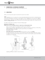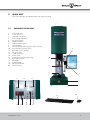
1
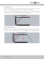
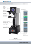
MANUAL
FH-11 SERIES
Universal Hardness Tester
Firmware Version 1.13
Changes in products and/or product specifications can emerge due to new technologies and
continuous development.
We reserve the right to change or modify
specifications of products without prior notice.
We recommend you to contact our sales office for
up-to-date information.
© All rights reserved
USER MANUAL
FOR
FH-11 SERIES
HARDNESS TESTING INSTRUMENT
Thank you for buying this advanced TINIUS OLSEN® hardness testing instrument.
The product meets the applicable DIN, ISO-EN, ASTM and JIS standards.
Before using this instrument, read through this user manual carefully to use the product properly.
After reading, keep the manual in an easy-to-access place for referencing whenever needed.
Read the “Safety Cautions” and “User’s Guide” thoroughly before usage, and properly operate the product.
In order to use the product safely, do not ignore visual cautions, warnings or safety symbols.
Pease refer to the limited guarantee and responsibility issues in the TINIUS OLSEN® guarantees conditions.
Manual FH-11 Series
1
2
Manual FH-11 Series
Make sure these signs and symbols are well understood before reading this manual or operating the instrument.
WARNING!
Ignoring this information and mishandling of the
equipment can lead to severe bodily injuries and
material damage.
-
Do not modify this equipment. Doing so can cause fire and/or electric shock.
Do not fabricate anything with the power cord, forcibly bend it, twist, or pull it, doing so can cause fires and/or
electric shock.
Do not disassemble this equipment. Doing so can cause electric shock. Contact our technical service department for
checks, adjustments, or repairs inside the equipment.
Do not operate the equipment at a voltage other than the power voltage that is indicated. Doing so can cause fires.
Do not place a vase, or any container holding water, near this equipment.
Fires can occur if water gets inside the equipment.
If, by any water does get inside the equipment, turn off the power to the equipment’s main unit, pull the plug out of the
socket, and call our company’s technical service department.
Always install grounding. If, by any chance a component gets damaged without grounding, electric shock can occur.
Do not operate the equipment if there is ever any abnormality, such as signs of smoke, unusual smell.
In such a case, turn off the power to the equipment’s main unit, pull the plug out of the socket, and call our company’s
technical service department.
Pull out the plug from the socket when exchanging a fuse. Not doing so can cause electric shock.
Do not insert or unplug the plug with wet hands. Doing so can cause electric shock.
Do not install the equipment on an unstable base. Doing so can affect the proper working and cause the equipment
to fall down and/or cause accidents and injuries.
Do not scratch or forcibly twist a cable.
Continued use of a cable after it is scratched or twisted can cause fire and/or electric shock.
Do not place the equipment in a high temperature and humidity location.
When cleaning or checking the equipment, make sure the plug is pulled out of the socket for safety.
Do not use fuses and illumination lamps other than those specified. Doing so can cause fire.
Do not connect special attachments to this equipment that are not “TINIUS OLSEN®” standard attachments, doing so
can cause poor performance or defects.
Do not use batteries other than the specified ones.
Do not block the halogen lamp area and ventilation. Blocking the ventilation can cause heat to accumulate inside the
instrument, which in turn, can generate fire.
Never open any of the panel or cover other than when unpacking or assembling.
High voltages existing in the instrument may cause electrical shocks to personnel.
Grounding, the power supply of the instrument must be grounded.
For the power cable, always use the power cable with 3-pins ground wire provided.
Manual FH-11 Series
3
INTRODUCTION
Thank you for buying the FH-11 series universal closed loop, force feed back, Rockwell, Vickers, Brinell, Knoop hardness
tester.
High-end universal hardness tester with low and high force ranging from 500gf to 3000Kgf.
The latest technology for a reliable fast measurement procedure.
•
•
•
•
•
Superior
Superior
Superior
Superior
Superior
Test Control
Accuracy
Gauge Repeatability & Reproducibility
Productivity
Flexibility
The FH-11 series universal hardness testers combine a practical design with universal specifications.
State-of-the-art closed loop, load cell technology and a - Patent Pending - force feedback system, assure fast test results at the
highest possible accuracy.
Unmatched consistency, repeatability and reliability now become affordable.
The TINIUS OLSEN® Instruments design team has used recently developed sensor technology to create a new industry
standard for Vickers hardness testing, eliminating weights and complex mechanical control systems.
The closed loop system applies force, calculates, filters and controls digital data in a 32-bits embedded CPU system.
The tester has a 6 position turret which can be customized by using different indentors, objectives, stages or Video systems,
meeting your particular request and your budget.
During the assembly process the FH-11 series will be configured to your particular technical requirements or even painted in
your company style colours.
The unique design offers the possibility to start with a basic system and to upgrade at a later stage. Force range, indentors &
objectives can be updated at any moment at any location in the world.
The FH-11 series is designed and built in The Netherlands, Europe, and meets all applicable EN, ISO and ASTM standards.
4
Manual FH-11 Series
Test procedure control
Traditional hardness testing systems use a “dead weight” mechanical design or inaccurate spring force mechanism to apply
the test force. Such systems are lacking test control, as there is no feed-back on the actual applied force.
The Closed Loop technology with a force feedback system, as applied in the FH-11 Series, constantly measures and controls
the applied force on the tester’s indentor and tested surface. Consequently, this superior control system offers an
almost unlimited selection of test loads and test rates for virtually any test condition imaginable.
Closed loop vs Dead weight
Selected
Force
Clo
sed
ad
de
Co
m
m
on
loo
pf
orc
e
we
ig
fee
ht
db
ack
sy
ste
m
s
Overshoot
Force
Time
Superior force control
Accuracy, reliability & efficiency
Elimination of overshoot due to sophisticated algorithms detecting contact with the indentor and the tested object’s surface.
The application and removal of the test force is fully automatic, as well as the positioning of the indentor and the pre-determined objective. The result is an absolute vibration free operation while reducing the operator’s workload to a minimum.
Closed loop vs Dead weight
Selected
Force
on
m
m
Co
Clo
sed
loo
pf
de
ad
orc
ef
we
ig
ht
eed
sy
ba
ste
ck
m
s
Overshoot
Force
Time
Manual FH-11 Series
High speed measurement
5
CONTENTS
1.
1.1
1.2
1.3
UNPACKING & CHECKING CONTENTS
Unpacking
Accessory Box
Accessories mounted on the tester (depending on purchased options)
8
8
9
10
2.
2.1
MAIN UNIT
Hardness tester body
11
11
3.
3.1
3.2
3.3
INSTALLATION OF THE HARDNESS TESTER
Installation conditions
Levelling
Installation of the indentors
12
1
13
13
4.
4.1.
PREPARING FH-11 FOR OPERATION
HORIZON™ Firmware
14
14
5.
5.1
5.2.
5.3.
5.4.
5.5.
5.6.
5.7.
5.8.
5.9.
5.10.
5.11.
5.12.
5.13.
5.14.
5.15.
5.16.
5.17.
5.18.
5.19
5.20
5.21
USING FH-11
Power on
Functions of HORIZON™
Scale selection
Manual/automatic
Conversion mode
Statistics
Dwell time
Diagrams
Limits
Archive
Tester
Visual
System
Service
Help
Program function
Indent measure function
Single measurement with save function
Delete single measurement
Escape function
Additional functions
15
15
16
17
22
23
24
25
26
27
28
29
32
34
36
37
38
40
42
42
42
43
6
Manual FH-11 Series
6.
6.1
6.2
6.3
CALIBRATION PROCEDURES
Force calibration
Objectives calibration
Maintenance advice
45
45
45
45
7.
PERIODICAL INSPECTION
46
8.
8.1
TECHNICAL SPECIFICATIONS, STANDARD DELIVERY AND ACCESSORIES
Technical drawings
47
50
9.
TROUBLE SHOOTING
51
10.
REPLACE OF FUSE
53
Manual FH-11 Series
7
1.
UNPACKING & CHECKING CONTENTS
This section describes unpacking conditions and standard accessories.
1.1 UNPACKING
When you receive the product, unpack it and check if all components are included.
NOTE:
While unpacking the unit, use no extreme force to remove the packing materials. The accessories box is placed next to the
instrument and separated by soft materials to avoid damage to the tester. REMOVE the accessory box first! STORE the
packing material in a safe place as you might need it again. Never ship or transport the tester without the correct packing
materials or with the transportation safety mounted between the turret and the spindle not being in the correct place. This can
cause severe damage to the tester.
The hardness testing machine must always be transported standing upright!
Delivered in a wooden case:
Handle the case very carefully. The tester is top-heavy and may topple easily.
-
Remove cover from upright case, by taking the steel clamps of the wooden panels.
Unpack accessories and check - against delivery bill - for completeness. In the case of discrepancy, re-check packing
material for hidden items. If the discrepancy persists, please inform your local distributor.
Remove plastic transport cover (bag).
Disassemble side walls.
Remove plastic hole covers at positions A and B.
Insert steel bar of approx. 75cm length, 25mm diameter through the top of the tester carefully.
Lift hardness-testing machine with care. Use a crane to lift the tester of the pallet and have it transferred to the place
of installation. The hoisting slings should be positioned on the steel bar in such a way that no pressure will be made
to the ABS top cover of the tester.
A
B
Unpacking and transport of hardness tester (wooden case)
8
Manual FH-11 Series
1
2
Lift the tester 50cm of the floor.
Remove four nuts with which the machine is fixed to the floor panel of the case (never transport the tester without
fixing it to it is original floor panel).
Putting hardness tester into place
When choosing the site of installation of a FH-11 series machine, make sure that the LCD screen will not be exposed to fierce
light.
1.2
-
ACCESSORY BOX
V-anvil ø80mm
Flat anvil ø80mm
Testing table ø200mm
Power cable
Adjustable vibration dampers
NOTE 1:
Some components or parts may be packaged separately and may not be included in the accessory box or may have been
installed on the hardness tester.
NOTE 2:
Special options may be set in the places which are left blank.
Manual FH-11 Series
9
1.3
1.
2.
ACCESSORIES MOUNTED ON THE TESTER (DEPENDING ON PURCHASED OPTIONS)
Motorized XY stage, round table inclination stage
Large testing table
2
1
10
Manual FH-11 Series
2.
MAIN UNIT
This section describes the individual parts of the main tester body
1
2.1
1.
2.
3.
4.
5.
6.
7.
8.
9.
10.
11.
12.
13.
14.
15.
16.
17.
18.
19.
20.
HARDNESS TESTER BODY
Front head cover
Touch screen 15”
Adjustable screen lever
Screen height adjustment
Emergency switch
Vibration dampers
Table and anvil support
Anvil (or table)
Motorized turret with 3 objectives and 3 indentors
Force actuator protection sleeve
Reset button (some models)
AC power input
4 USB connectors
Power switch
Connection for motorized XY stage
RJ45 LAN connector
Blind plate
Built-in W-LAN
Wireless keyboard
Wireless mouse
2
10
3
9
8
4
7
18
11
13
5
6
19
14
12
Manual FH-11 Series
20
15 16 17
11
3.
INSTALLATION OF THE HARDNESS TESTER
This section describes the correct way of installing your FH-11 series hardness tester
3.1 INSTALLATION CONDITIONS
Install the hardness tester system in the conditions shown below in order to make full use of its functions and performances
and to avoid defects or inaccuracy of any kind.
VIBRATION
Install the hardness tester in a place free from floor vibrations.
Install the hardness tester on a rigid floor securely fixed (Do not install it on a high or infirm floor.)
Do not install the hardness tester in a place where many people come and go.
Do not install the hardness tester near equipment generating vibrations.
Install the hardness tester on the first floor of a building if possible.
Do not install the hardness tester in a building near a road with heavy traffic.
Do not install the hardness tester in a building where a crane, vibration tester or similar equipment is installed.
NOTE:
Vibrations transmitted to the hardness tester result in inaccurate measurement in particular in low force application procedures.
WIND, SOUND & HUMIDITY
Do not install the hardness tester in a place directly exposed to the wind from an air conditioner, etc.
Do not install the hardness tester in a room with excessive air circulation.
Do not install the hardness tester near an entrance or an exit. (Wind and vibrations)
Do not install the hardness tester near equipment generating sound. (Acoustic vibrations)
Ambient temperature 10°C to 35°C
Recommended temperature: 21 ± 3
Ambient humidity 70% RH or less. No dew condensation allowed.
WORKBENCH
Place the hardness tester on a horizontal work bench (such as a cabinet, desk or table).
The installation area needed is not less than 600 mm in width, 850 mm in depth and 700 mm in height.
The work bench should be rigid and withstand a load over 250kg.
NOTE 1:
Do not apply any impacts to the hardness tester when moving it and do not tilt it by 30 degrees or more.
NOTE 2:
When carrying the tester, be careful not to bring your hands, etc. into contact with the turret.
12
Manual FH-11 Series
3.2 LEVELING
The FH-11 system is equipped with a unique load application system which is not sensitive to correct leveling.
Nevertheless, to eliminate possible wear and tear or the testers mechanical structure we advise to make sure that your tester
is correctly leveled.
Your FH-11 is standard supplied with 4 adjustable vibration dampers.
Install the dampers on the tester if not installed yet and use a correct key to adjust the height of each damper.
3.3 INSTALLATION OF THE INDENTORS
The FH-11 is equipped with pre-installed indentors following your particular request.
Indentors for this machine have specific dimensions and quality approval. Replacing the indentors by non-genuine indentors
(indentors from another manufacturer which are not original indentors) can lead to severe damage on your instrument
(which is not covered by guarantee) ALWAYS USE ORIGINAL PARTS.
Use a soft cloth to wipe any dirt or debris from the indentor holder or shoulder. The shank surface must face the screw hole
in the indentor holder when being inserted. Entirely and securely insert the shank into the holder. Before you test a specimen,
install an anvil and run a test on a test block to securely seat the indentor.
Manual FH-11 Series
13
4.
PREPARING FH-11 FOR OPERATION
The FH-11 is a complex mechanical/electronic equipment which requires professional installation from well trained staff.
We strongly recommend to opt for installation and training by TINIUS OLSEN service personnel.
Defect or damage caused by wrong operation or unsuitable installation are not covered by any warranty.
Make sure that the tester is calibrated (forces & test result) by TINIUS OLSEN® or any authorized service partner at your
location.
1.
2.
3.
4.
5.
6.
7.
8.
9.
Install the tester in a proper environment as described on previous pages.
Adjust the LCD screen in a proper position
Connect FH-11 with the mains and with your local area network (LAN)
Install a suitable anvil
Connect the tester with the main power.
Assure yourself that there are no objects between the turret and the test table.
Switch on the main power.
Wait until Windows has fully started and the user interface (HORIZON™) has been started (automatically).
Your are now ready to work with the FH-11.
4.1. HORIZON™ FIRMWARE
HORIZON™ is the advanced user operating system of the FH-11 series. The software incorporates, manual and automatic
measurement for all scales, image editing, file storing, image storing, report printing, turret operation, manual or automatic
focusing and many other advanced functions.
The firmware converts to 3 different hardness (and tensile) scales simultaneously. The conversions can be set to material and
standard (ISO/ASTM)
The system also controls an (optional) X-Y stage, rotary or inclining table that can be plugged into the standard built-in driver
of the tester. No additional charges, no external devices.
In combination with an X-Y stage the tester offers the option of running case depth hardness programs, pre defined testing
patterns and/or other specific or special tasks defined by the user.
All data can be copied or exported in to MS applications like Word, Excel, or a report generator that emails test results
directly to your workstation, or server. All data can be accessed over the LAN or WLAN connections.
14
Manual FH-11 Series
5.
USING FH-11
This section describes the correct way of getting started
5.1
POWER ON
Switch on the tester using the red color ON/OFF button on the back panel. Windows 7 will automatically start up.
Once Windows 7 has been initialized, it will automatically start up the TINIUS OLSEN® hardness testing firmware
HORIZON™. The following progress bar will appear.
NOTE 1:
Make sure that the emergency stop switch on the front side of the tester is not activated as the tester
hardware won’t power on in such case and one or more failure messages will appear on the screen.
NOTE 2:
If the tester has been started with the emergency switch turned off, turn the emergency switch slightly
to the right. If the switch was locked it will unlock automatically. Now close the HORIZON™
application in the following way: Press the button SYSTEM and choose the option EXIT in the menu.
Now restart the HORIZON™ application on your Windows screen.
NOTE 3:
A correct start up of your HORIZON™ system and the hardness tester hardware will show the
following screen without any failure or error messages.
Fill in the user name and password that has been
supplied to you in the attached envelop.
Press ENTER
The username/password box and keyboard will
disappear from your screen and the user interface
HORIZON™ is unlocked and ready for operation.
NOTE:
If the tester has been used before, you also might log in
with your stored username and password.
Manual FH-11 Series
15
5.2. FUNCTIONS OF HORIZON™
Your tester is equipped with a touch screen. Push gently in the middle of the designated buttons for tester operation.
Do not use any sharp objects. If you find the touch screen inconvenient, you might use the external keyboard and mouse.
1
2
3
4
5
6
7
8
9
10
11
12
1.
2.
3.
4.
5.
6.
7.
8.
9.
10.
16
13
14
15
18
17
19
20
21
22
23
24
25
26
27
32
33
28
31
29
30
43
41
42
40
35
36
38
31.
32.
33.
34.
35.
36.
37.
38.
39.
40.
41.
42.
43.
16
34
37
39
11.
12.
13.
14.
15.
16.
17.
18.
19.
20.
21.
22.
23.
24.
25.
26.
27.
28.
29.
30.
Scale selection
Handle archive
Tester settings
Visual settings
System settings
Service settings
Help function/manual
Program file indication
Manual or automatic tester
operation
Rockwell depth indication,
Vickers, Brinell diameter
reading
Measured value
Results list
Conversion mode
Statistics ON/OFF
Dwell time setting
Indentation video screen
Statistics bar
Diagrams selection
Limits settings
Program mode
Delete one or all
Escape to live screen
Save test results
Measure indentation
Full screen mode
Zoom indentation
Print results report
Zero depth reading scale
Shape correction settings
Test Pattern (optional)
Force control indication
Position and speed indication
Diagrams screen
Start/Stop button
Illumination control
Toggle between light sources
XY stage controller, return to centre
XY stage direction buttons
Start auto focus
Focus UP/DOWN button
Fast head UP/DOWN buttons
Push to turn turret clockwise
Turret position indicator
Manual FH-11 Series
5.3. SCALE SELECTION (1)
Press button number 1 for scale selection.
This function allows you to choose the required test scale and it’s particular settings
1
Available scales depend on particular tester
configuration (FH-11-0000, FH-11-0001 or FH-11-0002).
Press on the required scale button.
In this particular screen Rockwell has been highlighted.
Next to the column of hardness testing procedures,
you find an overview of Rockwell scales, press the
required scale.
Manual FH-11 Series
17
After pressing the required scale the tester has been setup
for Rockwell testing.
The user interface will display all settings as shown on
the left side.
18
Manual FH-11 Series
In this particular screen Vickers has been highlighted.
Next to the column of hardness testing procedures,
you find an overview of Vickers forces, press the
required force.
After pressing the required force the tester has been setup
for Vickers testing.
The user interface will display all settings as shown on
the left side.
Manual FH-11 Series
19
In this particular screen Brinell has been highlighted.
Next to the column of hardness testing procedures,
you find an overview of Brinell forces, press the
required force.
In this particular screen HBT has been highlighted.
Next to the column of hardness testing procedures,
you find an overview of HBT scales, press the
required scale.
20
Manual FH-11 Series
In this particular screen HVT has been highlighted.
Next to the column of hardness testing procedures,
you find an overview of HVT scales, press the
required scale.
In this particular screen BALL has been highlighted.
Next to the column of hardness testing procedures,
you find an overview of Ball indentation forces, press the
required force.
Manual FH-11 Series
21
5.4. MANUAL/AUTOMATIC (9)
The FH-11 series offers you the possibility to test in the manual or automatic mode.
Manual mode:
In the manual working modus FH-11 requires operator action for each step in the indentation and measuring procedure.
After selecting the correct scale, push the START button. FH-11 will now start to make the indentation procedure.
This, regardless of the testhead position (make sure the indentor is close to the surface of the workpiece to avoid long approach
time). After an indentation has been made, the tester will stop.
In case of a Rockwell test, the test value can be read from the screen on position 11.
In case of Vickers or Brinell tests, the indentation will be shown on the video screen.
Now press MEASURE (button 24) enter into the measuring menu. Press MEASURE again for automatic measurement of the
indentation or measure manually to determine the indentation width or diameter.
Store the values if required.
Automatic mode:
In the automatic mode the FH-11 will not required operator action, besides pressing the START button.
After pressing the START button, the tester will make an indentation according to tester settings and measure the indentation
width or diameter (in case of Vickers, Brinell or Knoop), displays and offers the option to delete or store the test values.
In this particular screen Manual mode has been
highlighted. Press MANUAL to proceed the manual
operation or AUTOMATIC to proceed the automatic
operation.
9
24
22
Manual FH-11 Series
5.5. CONVERSION MODE (13)
Hardness testing values of one certain scale can be converted to three other hardness scales (Tensile scale) simultaneously.
By pressing the button(s) 13 (3 buttons) a screen of
applicable standards appears. You can choose from
conversions according to ISO 18265, ASTM140,
GB/T1171 tables.
13
13
13
In this example we have set a Vickers HV10 test scale
with conversion to ASTM140 conversion tables.
Only selectable choices have been highlighted.
Press the conversion button that fits to your requirement.
Conversion settings that can not be selected in
combination with the tester setting (Vickers HV10) have
been faded.
13
13
13
Repeat this procedure for any of the 3 conversion
displays for simultaneous hardness indication of different
hardness scales.
Remember that each possible hardness test scale allows
different conversion settings.
Manual FH-11 Series
23
5.6. STATISTICS (14)
The video window (16) can show an additional information field also indicated as the statistics bar. If statistics are switched
to ON, a light grey bar will appear on the bottom of the video screen showing all online statistics such as quantity of
measurements, min. value, max. value, average value, etc.
By pressing the button ON and the statistics bar will
appear in the video frame.
By pressing the button OFF, the statistics bar disappears
from the video frame.
14
24
Manual FH-11 Series
5.7. DWELL TIME (15)
The dwell time setting (is the time that the indentor will remain under force on the to be tested material) and can be easily
changed at any moment (NOT during testing).
By pressing the button DWELL (15) a screen with 3
different dwell time settings will appear.
The most important setting for normal testing
circumstances is the MAIN LOAD DWELL TIME.
Use the arrows to in- or decrease the dwell time and press
on the dwell time number to save the setting.
15
Manual FH-11 Series
NOTE:
Only change pre-load dwell time or recovery dwell time
if particular testing circumstances describe off standard
values. Make sure that pre-load dwell time and recovery
dwell time will match the required ISO, ASTM, or JIS
standards.
25
5.8. DIAGRAMS (18)
HORIZON™ automatically calculates the hardness diagram, such as CHD and displays the graphic in the graphics
window position 33.
By pressing the button DIAGRAM (18) you get access to
additional optional diagrams. Ask the sales department
for more details.
18
33
26
Manual FH-11 Series
5.9. LIMITS (19)
To allow fast GO/NO GO procedures, test limits can be set. Once limits has been set the actual measured hardness value
will display in either a green field (11) in case of GO or red field in case of NO GO.
By pressing the button 19 you get access to the upper
and lower limits settings. Use the keyboard* that appear
in the left bottom corner of your screen to enter the
required hardness numbers.
11
Mark the position ACTIVE to activate the limit settings.
Press OK to save the setting.
After LIMITS has been set, upper limit bar (blue) and
lower limit bar (red) will appear in the diagram.
19
*
Manual FH-11 Series
27
5.10. ARCHIVE (2)
Storage of test results.
After one single or a number (batch or test has been performed) the results can be stored for later use. HORIZON™ stores
test results, statistics, individual numbers and video images in case of Vickers Knoop and Brinell.
The system further stores test dates, user ID and workpiece information.
2
By pressing the button ARCHIVE (2) the following options
will appear on your screen: Open, close, save and
delete.
Press the required choice.
In the following example we will store a test result.
By pressing OPEN, the archive opens and shows a list of
stored test results.
Press the required choice.
Select the test result storage line if you want to open the
file in the testers main screen.
By pressing CLOSE, the selected file closes and the main
screen shows the previously selected testing parameters.
By pressing SAVE, you are required to fill in a file name
before storing the test results in the data base.
By pressing DELETE, you can delete a test result or a file.
28
Manual FH-11 Series
5.11.
TESTER (3)
Turret configuration
The FH-11 series is equipped with 6 position (revolver) turret The turret holds a free definable set of indentors and objectives.
The calibration of all 6 positions is a high precision task which can only be done by TINIUS OLSEN® service staff. Never
untighten any indentor base or objective base as this will disturb the alignment and the accuracy of each turret position.
In order to run successful automatic hardness testing programs the turret configuration needs to be set accuracy indicating the
correct mounted indentors and objectives. Indentors and objectives can be freely positioned in the therefore preserved spaces.
3
By pressing the button TESTER (3) a submenu opens and
allows you to choose from TURRET CONFIGURATION,
XY STAGE and INFO.
TURRET CONFIGURATION allows you to fix and
indicates indentors and objectives positions.
INFO shows all relevant tester specifications.
By pressing the button TURRET CONFIGURATION a
pop-up window will display the graphic image of the
turret and the current settings.
The numbers in the small circle are the respective turret
position numbers.
In the large blue circle you can find the corresponding
mounted indentors and/or objectives.
USE OF XY STAGE!
Only use original TINIUS OLSEN® accessories on your
FH-11. XY STAGE allows you put it ON or OFF. When the
XY STAGE is on, you are limited in your choices of forces,
due to the maximum capacity of the XY STAGE.
NOTE:
MAKE SURE THAT WHEN THE XY STAGE IS MOUNTED
ON YOUR TESTER, THE SELECTION XY STAGE IS
TURNED TO ON.
IF THE SELECTION XY STAGE IS TURNED TO OFF,
IT MIGHT BE POSSIBLE TO OVERLOAD YOUR XY STAGE,
RESULTING TO SEVERE DAMAGE OR TOTAL LOSS OF
YOUR XY STAGE.
Manual FH-11 Series
29
Press on the turret position number to open the settings
for the corresponding turret position. Choose from the
pop-up screen the required indentor setting.
Objective positions can only be set or changed in the
service mode. This because calibration of the objectives
is required under all circumstances.
After setting the correct indentor a new pop-up screen will
be shown. Use the head up and head down function to
put the indentor close to the to be tested material and
press START. FH-11 will now calibrate the correct
indentor length in the turret settings firmware.
If a larger space between the indentor and workpiece is
required, you can use the blue up arrow to simulate a
larger indentor.
Understand that a large distance between the indentor
and workpiece, will influence test speed in a negative
way.
Understand that by shortening the indentor length
manually there will be no space between the indentor
and the workpiece. And a collision (worse case: crash)
with indentor damage could be the result.
BE VERY CAREFULL WITH MANIPULATING THE
INDENTOR LENGTH.
Press OK if the settings are correct.
30
Manual FH-11 Series
In case you try to change a objective setting, the
following pop-up screen will show you a warning!
By pressing INFO in the TESTER menu, the display shows
all relevant tester specifications.
Manual FH-11 Series
31
5.12.
VISUAL (4)
All settings related to the quality of the video image can be done from this option.
4
By pressing VISUAL, a subscreen displays the possible
video settings.
With CONTRAST you can set the contrast position.
AUTO-FOCUS enables you to focus on the material
surface without mechanical surface workpiece detection.
RESOLUTION makes it possible to work in standard in
HALF (standard) or FULL RESOLUTION (slow) mode.
By pressing CONTRAST a pop-up screen opens a virtual
slider that can be operated by hand or by mouse.
Besides CONTRAST also BRIGHTNESS can be adjusted.
RESET returns the slider to the factory position.
OK stores the setting.
32
Manual FH-11 Series
AUTO-FOCUS enables you to focus on the material
surface without mechanical surface workpiece detection.
Press AUTO-FOCUS and wait until the image in the
indent video field has sharpened.
This process normally applies automatically before
Vickers or Brinell indentations if the tester is set to
automatic.
RESOLUTION makes it possible to work in HALF
(standard) or FULL RESOLUTION (slow) mode.
Manual FH-11 Series
33
5.13. SYSTEM (5)
This menu allows you to set, change or delete users, usernames, user rights and passwords. The menu allows you to logout
from the HORIZON™ firmware as a user or to exit from the HORIZON™ firmware and return to the
Windows 7 main screen.
5
Press position 5 to enter in to the system settings menu.
Press USERS to add or edit usernames and passwords.
Press PASSWORD to change the password of an existing
user.
Press LOGOUT to logout the current user.
Press EXIT to exit from the HORIZON™ firmware and
return to the Windows 7 mainscreen.
NOTE:
The user ADMIN can not be deleted.
Press USERS to add or edit usernames and passwords.
Press + to enter a new user with a new password.
Press - to remove a user and password (except ADMIN).
The arrows up and down allow you to scroll through the
user list.
Press OK to save the changes.
34
Manual FH-11 Series
Press PASSWORD to change the password of an existing
user.
Enter the old password, then enter the new password.
Enter the new password again (at confirm).
If you do not want to store any changes, press CANCEL.
Manual FH-11 Series
35
5.14. SERVICE (6)
This SERVICE menu allows access to important machine settings. Pending the password certain levels of the machine setting
can be reached. Your distributor has access to the password that is required for calibration and adjustments.
The TINIUS OLSEN® service engineer has access to a higher level of machine settings.
6
It is strongly recommended NOT TO MAKE ANY
CHANGES to the machines factory settings.
If any changes are made to the standard factory settings,
which result to the malfunctioning of the tester or the
firmware and such intervention of TINIUS OLSEN® is
required, the support will be charged.
If calibration is required, please contact your supplier or
TINIUS OLSEN® directly.
36
Manual FH-11 Series
5.15. HELP (7)
Press HELP to enter this manual electronically. The manual is stored as a PDF file.
7
Manual FH-11 Series
37
5.16.
PROGRAM FUNCTION (20)
One of the FH-11 functionalities is to store test programs for frequently returning testing tasks/objects.
This will reduced the set-up time of your tester.
Set-up your tester for your workpiece as described in the
manual.
By pressing PROGRAM you can save the current tester
settings.
20
Enter a program name suitable for your workpiece.
It might be text or numbers or a combination of both.
By pressing SAVE you store the program including it’s
settings.
38
Manual FH-11 Series
To select an existing test program, press VIEW in the
program screen. The list with previously stored test
programs opens.
Press on the required program line.
Press SELECT to load a test program or press DELETE to
delete a test program.
NOTE:
All programs that are created by TINIUS OLSEN® can not
be deleted.
Press CANCEL to exit from this function.
Manual FH-11 Series
39
5.17.
INDENT MEASURE FUNCTION (24)
After an indentation has been made (Brinell, Vickers, Knoop) the tester will either perform a automatic test if the function 9
has been switched to automatic. If function 9 has been switched to manual the system will not proceed with an automatic
measurement.
AUTOMATIC
Make a hardness indentation according to your
requirement. After the indentation has been made the
turret will position to the original pre-indentation set
objective, for image viewing.
After a second 4 crosslines will appear on the screen.
The crosslines will than automatically position on the
edges of the indentation.
After this process the hardness value will appear on the
screen.
9
24
MANUAL
Make a hardness indentation according to your
requirement. Position the turret with the correct objective
for indentation viewing over the indentation.
Focus so that the image is sharp. Now press measure.
After a second 4 crosslines will appear on the screen.
Press measure again; the crosslines will now
automatically position on the edges of the indentation.
After this process the hardness value will appear on the
screen.
FINE ADJUSTMENT
Press on 1 of the yellow pyramids at the end of the
crossline. The diagram screen will now change to the fine
adjustment and zoom screen.
Select 1 of the crosslines by touching the croslline or the
yellow pyramid. Use the 4 red arrows to navigate the
crossline to the required position. The selected crossline
will be highlighted red.
To ease your task a magnified section of the indentation
pops up on the left top corner of the video screen.
Press again on the pyramid of the selected crossline to
deselect, or select directly another crossline. Repeat this
procedure for each crossline if required.
The adjusted hardness value shows directly on the screen.
40
Manual FH-11 Series
UNSUITABLE MEASUREMENT
If the difference between length of the horizontal and
vertical diagonal varies with 5% or more your
measurement is out of ISO/ASTM specification. Therefore
the hardness value will be showed in a red background.
Press SAVE to store the values anyway or press ESCAPE
to return to the main screen and make a new indentation.
NOTE:
If a measurement is outside the tolerance of international
standards both the SAVE and DELETE button will flash.
While the diameter and the test result screen will turn red.
Manual FH-11 Series
41
5.18.
SINGLE MEASUREMENT WITH SAVE FUNCTION (23)
After a measurement has been made you can store the testresult in the batch file of measurements.
SAVE stores an individual reading into the batch list.
After a measurement has been made the SAVE button will
flash (red), indicating that you can store the results.
The result will be added to the batch overview (12) and
the system is ready for the next test.
12
21
22
23
5.19 DELETE SINGLE MEASUREMENT (21)
After a measurement has been made you can store the testresult in the batch file (12) of measurements. You can also delete
a selected individual reading from the batch list. Select individual value (reading) and press DELETE. The following screen will
appear:
DELETE ONE:
Deletes the selected reading from the batch list.
DELETE ALL:
Deletes the entire batch list.
CANCEL:
Closes the delete function without deleting.
5.20 ESCAPE FUNCTION (22)
After or during a measurement pressing ESCAPE will return you to the main screen.
42
Manual FH-11 Series
5.21 ADDITIONAL FUNCTIONS
FULL SCREEN function (25)
By pressing FULL SCREEN the video viewing field of the
indentation maximizes to full screen mode.
Press the button again to returning to normal viewing
mode.
ZOOM function (26)
By pressing ZOOM a pop-up screen will appear. A slider
allows you to enlarge the indentation size to your
requirement. PLUS (+) enlarges the image and minus (-)
reduces the size of the image. The red arrows enable to
move the zoomed image in 4 directions on the screen.
25
26
27
29
PRINT function (27)
By pressing PRINT a PDF will appear on your screen
containing all test data such as all statistics, diagrams,
tester settings, measured values, etc. Press OK to print or
ESC to the main menu.
SHAPE CORRECTION function (29)
In cases where round materials are tested the actual
readings need to be computed in a different way. By
pressing SHAPE CORRECTION a pop-up screen allows
you to enter the diameter of the round or curved object to
be tested.
28
ZERO DEPTH function (28)
By pressing ZERO DEPTH the relative position off the
indentor is put to zero. This can be useful if in particular
cases an absolute position indication of the indentor
distance from the workpiece is required.
Manual FH-11 Series
43
43
41
35
40
37
39
34
36
42
38
34
Start/Stop button (34)
Press this button to START the testing sequence. While the
tester is performing a test, or any procedure, the START
button turns into a STOP button. Press STOP to stop the
tester.
Illumination control (35)
The arrows UP and DOWN allow to control the internal
or external illumination source.
Toggle between light sources (36)
Pressing the button 36 changes the light source from
internal (through objective) to ringlight.
XY stage controller, return to centre (37)
Pressing this button will return the optional XY stage to its
ultimate centre position.
XY stage direction buttons (38)
The XY buttons can be used for positioning the optional
XY stage in the required direction manually.
(For automatic traverse measurement, purchase the
optional software package)
Start auto focus (39)
By pressing this button the tester will perform a fully
automatic procedure to focus on the test object surface.
The focussing procedure exist of two parts, mechanical
auto-focus, image analyzing auto-focus.
Focus UP/DOWN button (40)
Use these buttons for manual focus or fine positioning.
Fast head UP/DOWN buttons (41)
Use these buttons for rough positioning of the test head.
Push to turn turret anti-clockwise (42)
By pushing this button the turret will turn anti-clockwise to
the next available position. It is also possible to push
directly on the required turret position.
Turret position indicator (43)
The selected turret position will be highlighted red.
44
Manual FH-11 Series
6.
CALIBRATION PROCEDURES
The FH-11 is equipped with a highly sensitive and accurate load cell system. The settings of the electronic system are calibrated
at the TINIUS OLSEN® assembly lab and is brought to ultimate performance before the tester was shipped to you.
It’s unlikely that you need to adjust any settings of your FH-11 in the normal product live.
It is recommended however to ask the TINIUS OLSEN® service department to have your tester inspected periodically and to
calibrate (if necessary) the force application system.
6.1
FORCE CALIBRATION
In the event that the force application of your tester needs to be recalibrated please seek advice from your supplier or contact
the service department of TINIUS OLSEN® directly.
To calibrate the applicable force of your FH-11 hardness tester, specific equipment is required (range of calibrated precision
load cells).
6.2
OBJECTIVES CALIBRATION
During the assembly process, the objectives on your FH-11 tester have been calibrated. Such calibration applies to the
particular objectives. Replacing objectives requires calibration of the optical path. Such calibration can only be done by your
supplier or contact the TINIUS OLSEN® service department directly.
6.3
MAINTENANCE ADVICE
Do not clean your tester with chemical solutions such as “thinner” or white spirit as this can cause permanent damage to the
painting, metallic surfaces or plastics.
Do not use aggressive or abrasive materials.
In case any part needs replacement, use genuine TINIUS OLSEN® parts in order not to disturb the performance of your tester.
Manual FH-11 Series
45
7.
PERIODICAL INSPECTION
Inspect the following before every hardness test and periodically.
46
Part
Indenters
Objective or lens
Anvil
Attention
Tip dirty
Lens surface polluted
Rust
Action
Wipe indenters
Wipe lens
Remove rust
Testblock
Rusted
Replace test block
Precaution
Do not use excessive force
Do not use excessive force
Do not scratch the surface
with abrasive materials
Do not use rusted test block
Manual FH-11 Series
8.
TECHNICAL SPECIFICATIONS, STANDARD DELIVERY AND ACCESSORIES
Hardness resolution
Objectives
Test loads
Rockwell test scales
Vickers test range
Brinell test range
Indentors (optional)
Workpiece accommodation
Force tolerance
Force control
Tester color (standard)
Light source
Machine dimensions
Machine weight
Power consumption
Power supply
0.01 Rockwell, 0.1 Vickers, 1 Brinell
3 installed for 0.7x to 1000x
1kgf/9.8N, 2kgf/19N, 2.5kgf/24N, 3kgf/29N, 4kgf/39,2N 5kgf/49N,
6.25kgf/62N, 10kgf/98N, 15.625kgf/153N, 20kgf/196N, 25kgf/245N,
30kgf/294.2N, 31.25kgf/306N, 50kgf/490N, 62.5kgf/612N, 100kgf/980.7N;
120kgf/1176N, 125kgf/1225N, 187.5kgf/1838N, 250kgf/2.45kN, 500kgf/4.9kN,
750kgf/7.35kN, 1000kgf/9.8kN, 1500kgf/14.7kN, 3000kgf/29kN
A, B, C, D, E, F, G, H, K, L, M, P, R, S, V, 15N, 30N, 45N, 15T, 30T, 45T, 15W,
30W, 45W, 15X, 30X, 45X, 15Y, 30Y, 45Y, HRM
HV:
1kgf/9.8N, 2kgf/19N, 3kgf/29N, 4kgf/39,2N, 5kgf/49N, 10kgf/98N,
20kgf/196N, 30kgf/294.2N, 50kgf/490N, 100kgf/980.7N, 120kgf/1176N
HVT:
50kgf/490N, 100kgf/980.7N
HB1:
1kgf/9.8N, 2.5kgf/24N, 5kgf/49N, 10kgf/98N, 30kgf/294.2N
HB2.5:
6.25kgf/62N, 15.625kgf/153N, 31.25kgf/306N,
62.5kgf/612N, 187.5kgf/1838N
HB5:
25kgf/245N, 62.5kgf/612N, 125kgf/1225N, 250kgf/2.45kN, 750kgf/7.35kN
HB10:
100kgf/980.7N, 250kgf/2.45kN, 500kgf/4.9kN, 750kgf/7.35kN,
1000kgf/9.8kN, 1500kgf/14.7kN, 3000kgf/29kN
HBT:
5kgf/49N, 250kgf/2.45kN
Brinell Balls: 1mm, 2.5mm, 5mm, 10mm
Vickers Diamond: 136°
Rockwell Diamond Cone: 120°
Rockwell balls: 1/16”, 1/8”, 1/4”, 1/2”
Vertical capacity
300mm (opt. 500mm)
Horizontal capacity
220mm (from center-line)
Max. < 1%
1 - 99 sec
Green / Metallic silver
White power LED (Opt. green/blue/red)
400mm x 650mm x 1440mm (WxDxH),
242kg
1 Amp
100V AC to 240V AC, 50Hz/60Hz, single phase
Standard delivery
•
Flat anvil ø80mm
•
V-anvil ø80mm
•
Testing table ø200mm
•
Certificate
•
Installation and user manual
Optional accessories
•
Certified indentors and reference blocks (DKD, UKAS, ASTM)
•
Large testing table 350mm x 250mm with T-grooves
•
Extra large testing table 450mm x 350mm with grooves and support
•
Long bar supports, to ease testing long bars
•
Motorized X-Y stages, motorized rotary or tilting tables
•
Built-in 5 axis support driver
Manual FH-11 Series
47
TECHNICAL SPECIFICATIONS
48
MODELS
FH-11-0000
UNIVERSAL
SCALES/TEST LOADS/FORCE
ROCKWELL, A, B, C, D, E, F, G, H, K, L, M, P, R,V
SUPERFICIAL ROCKWELL, N, T, X, Y
MACRO ROCKWELL HRM
VICKERS HV
KNOOP
HVT
BRINELL
HBT
H (Ball indentation) (ISO 2039/1)
1kgf to 250kgf
All scales
All scales
Yes
1kgf/9.8N to 120kgf/1176N
All scales
50kgf/490N, 100kgf/980.7N
1kgf/9.8N to 250kgf/2.45kN
5/250
Up to 250kgf/2.45kN
FORCE APPLICATION SYSTEM
Linear force actuator
Load cell, closed loop, force feed back system
Motorized heavy duty TURRET with 6 positions
Indentor positions
Objective positions
LED optical indent illumination
LED ring light indent illumination
Standard
Standard
Standard
3
3
Standard
Optional
OPTICAL MEASURING SYSTEM
5 mega pixels VIEW™ optical ZOOM system
Auto focus
Manual focus
Fully automatic indent measuring
Manual on screen indent measuring
Zoom and magnification ratio
Dual view™ working area overview camera
External Electronic Brinell microscope and objectives
Standard
Standard
Standard
Standard
Standard
0.7x to 1000x
Optional
No
DEPTH MEASUREMENT SYSTEM
Heidenhain™ high resolution optical system
Standard
HARDWARE AND USER INTERFACE
Built-in industrial Pentium PC and harddrives (RAID1)
Adjustable 15’’ full color industrial touch screen
MS Windows® 7 Ultimate license
HORIZON™ hardness testing firmware
Automatic image and file storage
Stores and handles 3000 files and images
Stores and handles 9000 files and images
Forms™ set of customized certificates
Universal motorized X-Y stage controls
Standard
Standard
Standard
Standard
Standard
Standard
Optional
Optional
Standard
CONNECTIVITY
External digital (DVI) TFT screen output
External keyboard and mouse connections
LAN (local area network connection)
WLAN (Wireless network connection)
Bi-directional RS-232
Printer / USB-2 output
Built-in motorized X-Y stage driver
Standard
Standard
Standard
Standard
Standard
Standard
Standard
Manual FH-11 Series
FH-11-0001
UNIVERSAL
FH-11-0002
UNIVERSAL
3kgf to 750kgf
All scales
All scales
Yes
3kgf/29N to 120kgf/1176N
All scales
50kgf/490N, 100kgf/980.7N
3kgf/29N to 750kgf/7.35kN
5/250
Up to 750kgf/7.35kN
10kgf to 3000kgf
All scales
No
Yes
10kgf/98N to 120kgf/1176N
No
50kgf/490N, 100kgf/980.7N
10kgf /98N to 3000kgf/29kN
5/250
Up to 3000kgf/29kN
Standard
Standard
Standard
3
3
Standard
Optional
Standard
Standard
Standard
3
3
Standard
Optional
Standard
Standard
Standard
Standard
Standard
0.7x to 1000x
Optional
No
Standard
Standard
Standard
Standard
Standard
0.7x to 1000x
Optional
No
Standard
Standard
Standard
Standard
Standard
Standard
Standard
Standard
Standard
Standard
Standard
Standard
Standard
Standard
Standard
Standard
Standard
Standard
Standard
Standard
Standard
Standard
Standard
Standard
Standard
Standard
Standard
Standard
Standard
Standard
Standard
Standard
Standard
Standard
Manual FH-11 Series
49
8.1 TECHNICAL DRAWINGS
50
Manual FH-11 Series
9.
TROUBLE SHOOTING
In exceptional cases your FH-11 will shown particular warning messages.
If you have any doubt about the working of your equipment, please contact the TINIUS OLSEN® service center.
Indentor not present!
No indentor has been selected. Enter into the turret
configuration menu and select the installed indentor.
LCA startup
Communication between PC and hardware is failing.
Close the HORIZON™ software and start the
software again.
Max down Reached!
The maximum down position of the force actuator has
been reached.
Press OK and use the UP button to release the
actuator from its lowest position.
Max up Reached!
The maximum up position of the force actuator has been
reached.
Press OK and use the DOWN button to release the
actuator from its highest position.
Either motor or Heidenhain does not work!
No displacement can be measured.
Either the motor or Heidenhain length measuring device
fails.
Restart the tester and try again.
Motor failure!
The force application motor fails to work.
Restart the tester, if the problem continuous
contact the TINIUS OLSEN® service center.
Manual FH-11 Series
51
Object detected
While the force actuator is traveling with rapid
displacement and an object would touch the turret,
the safety system will STOP the force application motor
immediately.
Remove the object and continuous the operation.
System not initialized!
WINDOWS failed to communicate with the
testers’ hardware.
Restart the tester and try again.
Timeout heidenhain readout
Communication failure between heidenhain length
measurement device and hardware.
Restart the tester and try again.
If the problem continuous, contact the TINIUS OLSEN®
service center.
Trinamic Timeout!
Communication failure between the turret and the
testers’ hardware.
Restart the tester and try again.
If the problem continuous, contact the TINIUS OLSEN®
service center.
52
Manual FH-11 Series
10. REPLACE OF FUSE
Disconnect electric power cable from backside of main body after turn off the machine and disconnect remove power line.
Pull out a fuse holder using screwdriver etc.
Fuse holder
Electric power connector
Inside
In the fuse holder, a fuse is stored.
Fuse in use
Reserve fuse
Outside
Fuse holder
Take out the fuse which is blown.
Inside
Outside
Mount the spare fuse
Connect electric power cable
Manual FH-11 Series
Inside
Outside
53
CORPORATE HEAD OFFICE
TINIUS OLSEN
Phone: +1-215-675-7100
Fax:
+1-215-441-0899
E-mail: [email protected]
1065 Easton Road,
Horsham, PA 19044-8009
USA
TINIUS OLSEN, LTD.
Phone: +44-1737-765001
Fax:
+44-1737-764768
E-mail: [email protected]
6 Perrywood Business Park, Honeycrock Lane,
Salfords (Near Redhill), Surrey RH1 5DZ
England
www.TiniusOlsen.com
www.MetalsTesting.com
IN11-319
TINIUS OLSEN INDIA PRIVATE LTD.
J3 SDF, NSEZ,
Noida Phase 2,
U.P. 201305, India