1
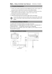
USER MANUAL V2.3 Radio Magnet Contact STM 250 Step Code EB March 3, 2015 Observe precautions! Electrostatic sensitive devices! Patent protected: WO98/36395, DE 100 25 561, DE 101 50 128, WO 2004/051591, DE 103 01 678 A1, DE 10309334, WO 04/109236, WO 05/096482, WO 02/095707, US 6,747,573, US 7,019,241 EnOcean GmbH Kolpingring 18a 82041 Oberhaching Germany Phone +49.89.67 34 689-0 Fax +49.89.67 34 689-50 [email protected] www.enocean.com Subject to modifications STM 250 User Manual V2.3 March 3, 2015 4:06 PM Page 1/18 USER MANUAL V2.3 STM 250 REVISION HISTORY The following major modifications and improvements have been made to the first version of this document: No Major Changes V1.6 Modified documentation for marketing as OEM product V2.0 Document rewritten due to changed internal electronics, product step code “EA” V2.1 Specification of shelf life improved. V2.2 Removed black variant V2.3 Security features added Published by EnOcean GmbH, Kolpingring 18a, 82041 Oberhaching, Germany www.enocean.com, [email protected], phone ++49 (89) 6734 6890 © EnOcean GmbH All Rights Reserved Important! This information describes the type of component and shall not be considered as assured characteristics. No responsibility is assumed for possible omissions or inaccuracies. Circuitry and specifications are subject to change without notice. For the latest product specifications, refer to the EnOcean website: http://www.enocean.com. As far as patents or other rights of third parties are concerned, liability is only assumed for modules, not for the described applications, processes and circuits. EnOcean does not assume responsibility for use of modules described and limits its liability to the replacement of modules determined to be defective due to workmanship. Devices or systems containing RF components must meet the essential requirements of the local legal authorities. The modules must not be used in any relation with equipment that supports, directly or indirectly, human health or life or with applications that can result in danger for people, animals or real value. Components of the modules are considered and should be disposed of as hazardous waste. Local government regulations are to be observed. Packing: Please use the recycling operators known to you. © 2015 EnOcean | www.enocean.com STM 250 User Manual V2.3 | Page 2/18 USER MANUAL V2.3 STM 250 TABLE OF CONTENT 1 2 3 GENERAL DESCRIPTION ................................................................................. 4 1.1 Basic functionality ......................................................................................... 4 1.2 Technical data............................................................................................... 4 1.3 Physical dimensions ....................................................................................... 5 1.3.1 Reed contact unit ...................................................................................... 5 1.3.2 Magnet unit .............................................................................................. 6 1.4 Environmental conditions................................................................................ 7 1.5 Ordering Information ..................................................................................... 7 FUNCTIONAL DESCRIPTION ............................................................................ 8 2.1 Block diagram ............................................................................................... 8 2.2 Radio telegram.................................................. Error! Bookmark not defined. 2.3 Transmit timing........................................................................................... 10 2.4 Energy consumption .................................................................................... 10 APPLICATIONS INFORMATION....................................................................... 15 3.1 Unit mounting ............................................................................................. 15 3.2 Recommendations for magnet positioning....................................................... 15 3.3 Transmission range ..................................................................................... 17 3.4 Connecting an external backup battery .......................................................... 17 4 AGENCY CERTIFICATIONS ............................................................................ 18 5 DECLARATION OF CONFORMITY, BRANDING ................................................... 18 © 2015 EnOcean | www.enocean.com STM 250 User Manual V2.3 | Page 3/18 USER MANUAL V2.3 STM 250 1 GENERAL DESCRIPTION 1.1 Basic functionality STM 250 is a wireless magnet contact. The radio sensor is powered by a small solar cell and by that it works absolutely maintenance-free. An integrated energy store allows operation for several days even in total darkness. STM 250 supervises an integrated reed contact and reports every status change immediately (open <> closed). In addition a sign of life signal is transmitted every 20-30 minutes. A LRN button is pre-installed on the PCB. When this button is pressed through a hole in the back plate a special teach-in signal is sent. The reed contact housing and the magnet housing are very small. This means that the EnOcean magnet contact is unobtrusively mountable at every window frame made of aluminum, plastic or wood. STM 250 is designed and qualified for the indoor use in building automation & installation, not for industrial applications (in cause of ESD protection). Typical applications are window, flap and door monitoring. The STM 250 in 868 MHz include the enhanced secure mode. In enhanced secure mode the communication is protected by enhanced security features e.g. encryption. The modules can be switched from standard mode (without enhanced security) to enhanced mode and back by long press of LRN button in field operation. 1.2 Technical data Antenna Pre-installed helical antenna installed Frequency Radio Standard EnOcean Equipment Profile1 Data rate/Modulation type 868.3 MHz EnOcean 868 MHz/315 MHz EEP D5-00-01 125 kbps/ASK Conducted Output Power Power Supply typ. 2 dBm2 Pre-installed solar cell Illumination 50-100000 lux typ. 6 days, min. 90 hours Initial operation time in darkness @ 25°C if energy storage fully charged transmission of telegram every 25 min on average Operation start up time with empty energy store Reed contact 1 2 typ. 2.5 min @ 400 lux / 25°C incandescent or fluorescent light 1x internal, Meder MK23-90-BV14496 or MK01-I http://www.enocean-alliance.org/fileadmin/redaktion/enocean_alliance/pdf/EnOcean_Equipment_Profiles_EEP2.1.pdf Matched to impedance of whip antenna (not 50 Ω) Full performance of the PAS614L energy storage is achieved after several days of operation (up to two weeks) at good illumination level. Performance degrades over life time, especially if energy storage is exposed to higher temperatures. Each 10 K drop in temperature doubles the expected life span. 3 © 2015 EnOcean | www.enocean.com 3 STM 250 User Manual V2.3 | Page 4/18 USER MANUAL V2.3 STM 250 Radio Regulations Encryption Algorithms 1.3 R&TTE EN 300 220 VAES 128, CMAC Physical dimensions 1.3.1 Reed contact unit Dimensions 110 x 19 x 15 mm 4 Color of housing signal white Material of housing PC/ABS Top view Side view Front view 4 Color may change by strong irradiation of sun light! © 2015 EnOcean | www.enocean.com STM 250 User Manual V2.3 | Page 5/18 USER MANUAL V2.3 STM 250 Access to teach-in pushbutton Bottom view 1.3.2 Magnet unit Dimensions Color of housing 37 x 10 x 5 mm 4 signal white Material of housing PC/ABS Top view Side view Front view Bottom view © 2015 EnOcean | www.enocean.com STM 250 User Manual V2.3 | Page 6/18 USER MANUAL V2.3 STM 250 1.4 Environmental conditions Operating temperature Storage temperature Shelf life (in absolute darkness) Humidity Protection class 1.5 -20 °C … +60 °C 5 -20 °C … +60 °C, recommended : +10 °C…+30 °C, <60%r.h. 36 months after delivery6 0% … 93% r.h., non-condensing IP 40, indoor use only Ordering Information Type Ordering Code STM 250 white S3101-C250 Packaging Units 100 pcs 5 Recommended for maximum life of energy storage capacitor Deep discharge of the PAS614L energy storage leads to degradation of performance. Therefore products have to be taken into operation after 36 months. At least the PAS614L needs to be recharged to 2.1V. 6 © 2015 EnOcean | www.enocean.com STM 250 User Manual V2.3 | Page 7/18 USER MANUAL V2.3 STM 250 2 FUNCTIONAL DESCRIPTION 2.1 Block diagram Helical antenna 16MHz Oscillator DOLPHIN EO3000I Power management Reed contact BALUN RF Transmitter 868.3 MHz Micro Controller Transmit Indicator Spontaneous wake-up LRN button Solar Cell Energy Storage A change of the reed contact status or pushing the LRN button will wake the transmitter unit to send a radio telegram immediately (reed contact position, LRN push button status, unique 32-bit sensor ID, checksum). In addition a redundant retransmission signal is sent to announce the contact status even in case of no input signal changes. This signal transmitted every 20-30 min, affected at random. The transmit indicator LED flashes briefly at every radio transmission. Between the wake-up phases, the device is in sleep mode for minimum power consumption. 2.2 Radio telegram STM 32x transmits a radio telegram according to EnOcean Equipment Profile EEP D5-00-01 as defined in the EnOcean Equipment Profiles specification. (http://www.enocean-alliance.org/eep/) By pressing the LRN button in standard mode an 1BS Teach-in telegram is transmitted. 2.2.1 Enhances security telegram The STM 250 can be operated in: Standard mode – no enhanced security is used. This is the common operation mode, originally available. This is also the default factory mode. © 2015 EnOcean | www.enocean.com STM 250 User Manual V2.3 | Page 8/18 USER MANUAL V2.3 STM 250 Security mode – communication is protected by enhanced security features. This mode was added later in module evolution. In secure mode of STM 250 the payload content of the telegram is always protected with advanced security features. Normal operation telegram payload and also Teach-in telegram payload are protected in the same way. The security features used are defined by the Security Level format - SLF. This parameter is set by default to the highest possible level: 24-bit RLC, No RLC TX 4-byte CMAC, VAES encryption The security features are added to the communication by encapsulating the payload and Teach-in telegram payload into a secured telegram. The payload itself is not changed and corresponds to the standard mode payload like defined in chapter 2.2. EEP D5-00-01. Please refer to the EnOcean Security Specification for details http://www.enocean.com/en/security-specification/. 2.2.2 Switching between modes STM 250 can be switched from normal mode to secure mode and vice versa by long press of the LRN Button. The behaviour of the LRN button is following: 1. Button is pressed – LED flashes briefly Teach-in is performed according to the actual mode. 2. Button is hold a. If released in period < 10 seconds then actual mode is kept. No further action. b. If hold for at least 10 seconds then the actual mode is changed (standard -> secure or secure -> standard). LED flashes briefly. Teach-in is performed according to the actual (new) mode. 3. Button is released – no action. Upon entry into secure mode, a secure teach-in telegram is sent by STM 250. Please see Chapter 2.2.3 for details. Before changing the operating mode please make sure to clear the device from all receivers which have been taught to work with this device before. Otherwise the receiver will ignore the telegrams and the application will not work. The flag for actual mode itself is stored in non-volatile memory. After power down reset the previous selected mode is active. Therefore mode change is limited to 50 times. In normal application scenario only very few are required. The factory delivery mode of the STM 250 is Standard – not encrypted. This mode is common mode originally available. Secure mode was added in later product upgrades. © 2015 EnOcean | www.enocean.com STM 250 User Manual V2.3 | Page 9/18 USER MANUAL V2.3 STM 250 2.2.3 Security Teach-In To process security communication on a receiver the STM 250 has to send a security teachin telegram to the receiver and so inform him about the used security profile, AES key and initial RLC counter. The security teach-in has to take place before any other communication can be executed (profile teach-in included). To trigger the transmission of the teach-in telegram press the LRN button. The security teach-in and then the profile teach-in are transmitted. The profile teach-in telegram is already protected by advanced security features. The process of sending security teach-in telegram and profile teach-in telegram is triggered by pressing the LRN button in secure mode. The behaviour of the LRN button is following: 1. Button is pressed 2. Security teach-in is send. 3. Profile teach-in is send. For more information on the structure of the teach-in telegram please refer to chapter 4.2 of http://www.enocean.com/en/security-specification/. 2.3 Transmit timing The setup of the transmission timing allows avoiding possible of other EnOcean transmitters as well as disturbances from transmission cycle, 3 identical subtelegrams are transmitted sion of a subtelegram lasts approximately 0.9 ms. The delay sion bursts is affected at random. collisions with data packages the environment. With each within 40 ms. The transmisbetween the three transmis- 2.3.1 Secure transmission timing In secure mode of STM 250 the transmission cycle includes 2 identical subtelegrams are transmitted within 20 ms. This is required to compensate the additional energy requirement of enhanced security computing and additional payload. The transmission of a subtelegram lasts approximately 1.2 ms. 2.4 Energy consumption 100 10 Current [mA] 1 0.1 0.01 0.001 0.0001 0.00001 0 10 20 30 40 50 60 70 80 90 100 Time [ms] © 2015 EnOcean | www.enocean.com STM 250 User Manual V2.3 | Page 10/18 USER MANUAL V2.3 STM 250 Charge needed for one measurement and transmit cycle: ~80 µC Charge needed for one measurement cycle without transmit: ~10 µC Calculations are performed on the basis of electric charges because of the internal linear voltage regulator of the module. Energy consumption varies with voltage of the energy storage while consumption of electric charge is constant. From these values the following typical performance parameters at room temperature have been calculated: Wake and transmit cycle [s] Operation Time in darkness [h] when storage fully charged Required reload time [h] at 200 lux within 24 h for continuous operation 1500 175 1.8 Assumptions: Internal storage PAS614L-VL3 (after several days of operation at good illumination level) with 0.25 F, Umax=3.2 V, Umin=2.3 V, T=25 °C Consumption: Transmit cycle 80 µC, measurement cycle 10 µC Pre-installed solar cell ECS 300, operating values 3 V and 5 µA @ 200 lux fluorescent light Current proportional to illumination level (not true at very low levels!) These values are calculated, the accuracy is about +/-20%! The performance varies over temperature and may be strongly reduced at extreme temperatures. 2.4.1 Consumption in enhanced security mode Enhanced security mode requires more energy due to encryption algorithm computing time and extended telegram length because of CMAC. This added consumption is compensated by reducing the subtelegram count to 2. With this measure the operation in dark time is even little bit increased. There it is to assume the operation in dark time is not reduced by using enhanced security. 2.5 Storing the Rolling code counter For the enhanced security features a RLC Counter needs to be stored in non-volatile memory. For security reasons the RLC Counter is incremented by every transmitted telegram. Together with the CMAC the RLC ensures that messages cannot be reproduced or forged. In STM 250 the RLC is stored in the Dolphin chip flash memory. To improve the endurance of the flash memory and also the energy budget not every increment is saved to the nonvolatile flash memory. During deep sleep the RLC is stored in RAM0 memory. The RLC storing algorithm is described in the following text. Constrains Writing a RLC (4bytes) into flash is not energy consuming. It is fast (μSec)and requires almost no extra energy. Erasing a flash page is energy consuming operation. It takes 40ms and requires extra energy. © 2015 EnOcean | www.enocean.com STM 250 User Manual V2.3 | Page 11/18 USER MANUAL V2.3 STM 250 For details on energy consumption for flash operation please see the Dolphin Chip Core specification. https://www.enocean.com/dolphin-core-description/ Strategy We implement a ring buffer which consist of multiple (16) pages The RLCs are written sequentially to the current page When the page is full we move to the next page When almost all pages are full, we erase the oldest page Diagram Legend Free page Partially written page Full page Pointer to the current page and direction how the rolling codes are written Pointer to the last/oldest page and direction how the flash pages are erased © 2015 EnOcean | www.enocean.com STM 250 User Manual V2.3 | Page 12/18 USER MANUAL V2.3 STM 250 First rolling code is written to flash Several pages are full Almost all flash were full, we deleted the first page Because the flash pages act as a ring buffer, this situation is also normal Definitions RLC - 32-bit counter value used for encryption and authentication. After a data telegram is send it is incremented by 1. RLCram0 - RLC value saved in RAM0. It contains the actual RLC value RLCflash - RLC value saved in flash. This value is older or the same as RLCram0 ΔRLC = RLCram0 - RLCflash . The difference between the RLCflash value saved in flash, and the current RLCram0 saved in RAM0. RLCSAVE-WINDOW is fixed to 30. Vcc - actual supply voltage [V] Von - voltage required to switch the chip ON after it was in OFF state. Voff - under this voltage the chip is switched off, RAM and RAM0 data are lost. Constrains We assume that the voltage will not drop from about Von to under Voff It has to be assured by HW and SW that any operation e.g. sending a telegram or erasing a flash page will not cause to drop the voltage from Von to under Voff Rules If Vcc > Von then increment the RLCram0 after the data telegram has been sent saving to flash is not needed If Vcc < Von and ΔRLC > RLCSAVE-WINDOW then the RLCram0 has to be saved to flash and RLCflash = RLCram0 send data telegram and increment RLCram0 If Vcc > 2.8V and flash memory is almost full then erase a flash page and go to deepsleep don't send any telegram - this would required even more energy, and the chip would probably switch off After the chip starts from power down read RLCflash from flash and set RLCram0 = RLCflash + RLCSAVE-WINDOW © 2015 EnOcean | www.enocean.com STM 250 User Manual V2.3 | Page 13/18 USER MANUAL V2.3 STM 250 Example Diagram For the illustration we set RLCSAVE-WINDOW equal to 4 © 2015 EnOcean | www.enocean.com STM 250 User Manual V2.3 | Page 14/18 USER MANUAL V2.3 STM 250 3 APPLICATIONS INFORMATION 3.1 Unit mounting Both the reed contact unit as well as the magnet contact unit is very thin and flat. This means that they are unobtrusively mountable at every window or doorframe made of aluminum, plastic or wood. Mounting position of the reed contact is horizontal, vertically or even tilted. The arrow signs on the base of the reed contact should be directed downward. In this mounting position, the STM 250 housing offers protection against splashing water drops. Mounting STM 250 on metal surfaces or aluminum window frames will reduce the transmission range. Therefore please note that a radio receiver unit should not be mounted in the same plane as the STM 250 base plate, because in extension of the metal surface the transmission range is reduced by physical radio transmission effects of the antenna near to metal. For example the receiver should not be mounted at the window front side. 3.2 Recommendations for magnet positioning The flat magnet should be positioned by facing the housing in the middle of the reed contact marking as follows: Reed contact marking Righted positioning of the magnet (Typical for window mounting) The magnet can be positioned in vertical or in horizontal position to the reed contact housing. The distance between housing and magnet should be less than 5 mm. Reed contact marking Planar positioning of the magnet © 2015 EnOcean | www.enocean.com STM 250 User Manual V2.3 | Page 15/18 USER MANUAL V2.3 STM 250 (Typical for door mounting) The round-pole magnet can be removed from the magnet housing. This enables smart embedding into wooden window casements in square position to the reed contact housing. But note that the round-pole must be mounted beside the reed contact marking, as follows: or: Pole-faced positioning of magnet (Typical for mounting at wooden window casements) The distance between housing and magnet should be less than 4 mm when using this mounting position. Always take care for sufficient distance of the magnet to magnetic data carriers, e.g. credit cards. Data could be erased! © 2015 EnOcean | www.enocean.com STM 250 User Manual V2.3 | Page 16/18 USER MANUAL V2.3 STM 250 3.3 Transmission range The main factors that influence the system transmission range are type and location of the antennas of the receiver and the transmitter, type of terrain and degree of obstruction of the link path, sources of interference affecting the receiver, and “dead” spots caused by signal reflections from nearby conductive objects. Since the expected transmission range strongly depends on this system conditions, range tests should categorically be performed before notification of a particular range that will be attainable by a certain application. The following figures for expected transmission range are considered by using a PTM, a STM or a TCM radio transmitter device and the TCM radio receiver device with preinstalled whip antenna and may be used as a rough guide only: Line-of-sight connections: Typically 30 m range in corridors, up to 100 m in halls Plasterboard walls / dry wood: Typically 30 m range, through max. 5 walls Ferroconcrete walls / ceilings: Typically 10 m range, through max. 1 ceiling Fire-safety walls, elevator shafts, staircases and supply areas should be considered as screening. The angle at which the transmitted signal hits the wall is very important. The effective wall thickness – and with it the signal attenuation – varies according to this angle. Signals should be transmitted as directly as possible through the wall. Wall niches should be avoided. Other factors restricting transmission range: Switch mounted on metal surfaces (up to 30% loss of transmission range) Hollow lightweight walls filled with insulating wool on metal foil False ceilings with panels of metal or carbon fiber Lead glass or glass with metal coating, steel furniture The distance between EnOcean receivers and other transmitting devices such as computers, audio and video equipment that also emit high-frequency signals should be at least 0.5 m. A summarized application note to determine the transmission range within buildings is available as download from www.enocean.com. 3.4 Connecting an external backup battery In case there is not sufficient light available for operation with solar cell an external 3 V Lithium backup battery can be connected to the PCB inside the module at the soldering pads shown below: © 2015 EnOcean | www.enocean.com STM 250 User Manual V2.3 | Page 17/18 USER MANUAL V2.3 STM 250 4 AGENCY CERTIFICATIONS The devices conform to the requirements for a CE marking and to the R&TTE EU-directive on radio equipment. The assembly conforms to the European and national requirements of electromagnetic compatibility. The conformity has been proven and the according documentation has been deposited at EnOcean. The devices can be operated without notification and free of charge in the area of the European Union, and in Switzerland. The following provisos apply: 5 EnOcean RF devices must not be modified or used outside their specification limits. EnOcean RF devices may only be used to transfer digital or digitized data. Analog speech and/or music are not permitted. EnOcean RF devices must not be used with gain antennas, since this may result in allowed ERP or spurious emission levels being exceeded. The final product incorporating EnOcean RF devices must itself meet the essential requirement of the R&TTE Directive and a CE marking must be affixed on the final product and on the sales packaging each. Operating instructions containing a Declaration of Conformity has to be attached. If the STM 250 transmitter is used according to the regulations of the 868.3 MHz band, a so-called “Duty Cycle” of 1% per hour must not be exceeded. Permanent transmitters such as radio earphones are not allowed. For approval aspects, it must be ensured that the STM 250 reed contact is not operated more than 13.000 times per hour (e.g. window opened or window closed). For this calculation the extraordinary short telegram length is considered including all subtelegrams. Also a tolerance of 5% in telegram length is included. DECLARATION OF CONFORMITY, BRANDING These products are offered solely as finished products for OEM customers and without an EnOcean label. The OEM partners as the instance responsible for marketing them must add their own CE declaration and product identification. The declaration of conformity can be produced on the basis of documentation provided by EnOcean. EnOcean assumes no responsibility of any kind for OEM products to end-users. © 2015 EnOcean | www.enocean.com STM 250 User Manual V2.3 | Page 18/18