1
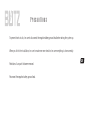
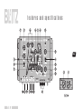
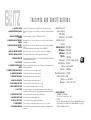
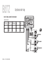
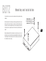
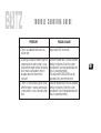
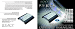
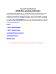
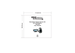
user’s manual
BZX-7
3-Way Electronic Crossover Network
with Subwoofer Level Control
INTRODUCTION...
Thank you for purchasing the Blitz High performance Electronic Crossover. Rest assured you have
purchased a quality product designed and engineered to give you many years un-compromised
musical service. The Blitz Electronic Crossover has been designed using the latest in electronic
technology available today.
When you check the list of features offered by the BZX-7, you'll know you made the right choice
with a Blitz Electronic Crossover network.
table of contents
general features
2
precautions
3
features and specifications
4-5
system wiring
6
mounting and installation
7
noise check and system adjustment
8
troubleshooting
9
general features
Chrome Plated Chassis
Clear Acrylic Protective Cover
Green Light Illumination
LED Power On Indicator
Front and Rear Inputs
In (Subwoofer)/ Out (Crossover/Amp) Selector and Ports
Subwoofer, Mid-Range, and High Pass Outputs with Gain Controls
Slope Rate: 12dB/Octave
Band Pass/ High Pass Selector on Mid-Range
Sub Level and Q. Selector (2-20 Variable) Remote Control
Subwoofer Stereo/Mono Selector
Subwoofer Selectable Phase Shifter
Adjustable Bass Boost and Bass Frequency (25 -250Hz) Controls
Adjustable Frequency Selector,
Low Pass: 40-400Hz, Mid Range: 40-7kHz, High Pass: 40-8kHz
Frequency Multiplier (x1, x10) on High Pass Output
2
Precautions
To prevent short circuits, be sure to disconnect the negative battery ground lead before wiring the system up.
When you finish the installation, be sure to make one more check to be sure everything is done correctly.
Reinstate all car parts that were removed.
Reconnect the negative battery ground lead.
3
features and specifications
4
features and specifications
1. INPUT LEVEL CONTROL
2. SUBWOOFER FREQUENCY CONTROL
3. BASS BOOST FREQUENCY LEVEL
CONTROLS
Turning this control to adjust the input sensitivity of the set to match the radio's output.
For selection of the Low-pass crossover frequency for the subwoofer channel between 40Hz and
400Hz.
For increasing the bass boost level up to +12dB from 25Hz to 250Hz.
4. MID RANGE / HIGH PASS FREQUENCY
SELECTOR
By turning the selector you can choose a high pass crossover point for the mid output between
40Hz-800Hz
5. MID RANGE / LOW PASS FREQUENCY
SELECTOR
By turning the selector you can choose a low pass crossover point for the mid output between
2-7KHz
This adjustment only applies when switch number 7 is placed on BAND PASS.
6. HIGH PASS FREQUENCY SELECTOR
By turning the selector you can choose the high-pass crossover points from 40Hz-8kHz.
7. HIGH PASS / BAND PASS SELECTOR
Positioning this switch is at high pass mode, the low pass filter cannot be used.
8. FREQUENCY MULTIPLIER
9. IN / OUT SWITCH
10. SUBWOOFER SELECTABLE PHASE
SHIFTER
Positioning this switch at the"10" changes crossover points from 40Hz-800Hz to 400Hz-8kHz for
high frequency high channel drivers.
See page 6 (signal connection diagram)
Allows you to change the phase of your subwoofer 0 or 180 degrees to help compensate for timing
differences between drivers.
11. SUBWOOFER STEREO/MONO SELECTOR
For selection of stereo or mono mode subwoofer output.
12. SUBWOOFER GAIN CONTROL
For adjusting the subwoofer channel output signal level.
13. MID RANGE GAIN CONTROL
For adjusting the mid range channel output signal level.
14. HIGH PASS GAIN CONTROL
For adjusting the high pass channel output signal level.
15. REAR CHANNEL INPUT PORT
To be connected to the rear channel outputs of the source unit.
16. FRONT CHANNEL INPUT PORT
To be connected to the front channel outputs of the source unit.
17. IN / OUT PORT
18. SUBWOOFER OUTPUT PORT
19. MID RANGE OUTPUT PORT
20. HIGH PASS OUTPUT PORT
21. POWER TERMINALS
22. LED POWER ON INDICATOR
You can use this connection if you have a third pre-amp audio source for the subwoofer in or
connect two or more BZX-7 modules out to create a system with an unlimited number of amplifiers.
To be connected to the subwoofer channel amplifier left/right inputs.
To be connected to the rear channel amplifier input.
To be connected to the front channel amplifier left/right inputs.
Use these connectors to deliver power, ground and remote turn-on control to the unit.
The LED indicator lights up when the internal switching power supply is activated and the unit
is operational.
Adjustable bass boost
and bass frequency
(25Hz- 250Hz)
Quality factor
Selectable crossover
frequency
- Subwoofer (Low Pass)
- Mid high pass
- Mid low pass
- High Pass
Power supply
Input impedance
S/N ratio
Slope Rate
Max output signal level
Channel separation
Distortion
Dimensions
20-2 (Variable)
40Hz-400Hz
40Hz-800Hz
2KHz-7KHz
40Hz-8KHz
10-16V DC, negative ground
10K Ohm
more than 85dB
12dB/Octave
7.0V RMS
60dB
less than 0.05%
1.8"H x 9.3"W x 6.4"D
5
REMOTE CONTROL UNIT
1 SUBWOOFER LEVEL CONTROL
This control sets the subwoofer level control.
2 Q SELECT
This control will narrow or widen the boost frequency bandwidth (Q=factor) being
sent to the amplifier for each band from Q=20(Narrow bandwidth, steep slope) to
Q=2 (Wide bandwidth, gentle slopes).
System wiring
IN/OUT SIGNAL CONNECTION DIAGRAM
IN/OUT SWITCH
SWITCH
POSITION
IN
OUT
VIA INPUT
SOURCE
FRONT
REAR
FRONT
REAR
OUTPUT
SUBWOOFER
ON
ON
ON
ON
MID
ON
OFF
OFF
ON
HIGH
ON
OFF
OFF
ON
6
TWEETER
MID-RANGE
SUBWOOFER
Mounting and installation
Your new Blitz Series crossover comes complete with all required mounting
hardware.
BTS-1 4ø x12N x 4
SW 4ø(B) x 4
Mark the location for the mounting screw holes by positioning the crossover
where you wish to install it and use a scribe (or one of the mounting screws)
inserted in each of the mounting holes to mark the mounting surface. If the
mounting surface is carpeted, measure the hole centers and mark with a felt
tip pen.
Before attempting to drill the mounting holes, take note of any wires, lines or
other devices in your vehicle which may be located behind the mounting surface!
Then drill pilot in the mounting surface for the mounting screws and insert
then. Tighten the screws securely.
PW 4ø(B) x 4
7
Noise check and system adjustment
NOISE CHECK
Check the entire audio system for noise before permanently securing the CROSSOVER mounting
1. Start the engine.
2. Turn the audio system on.
3. Rev the engine and vary the VOLUME of the audio system to determine if there is any unwanted noise.
If so, turn both the audio system and the engine off. Do not secure the CROSSOVER mounting screws. Refer to the "Trouble Shooting Guide" at this
manual.
4. If the audio system does not have any noise, securely tighten the CROSSOVER mounting screw and double check the wiring cables for safe placement.
SYSTEM ADJUSTMENT
Preliminary Adjustments
Pre-setting the system provides a necessary starting point for fine-tuning the entire audio system to maximum performance.
NOTE: DO NOT MOUNT CROSSOVER UNTIL THE FOLLOWING PROCEDURES HAVE BEEN COMPLETED.
1. Preset each amplifier input gain adjustment at the amplifier to half of maximum.
2. Before turning the audio system on, preset-adjust the front, rear and sub-woofer output level controls, as well as the front channel high-pass and subwoofer channel low-pass crossover points.
3. Slowly turn the volume up and listen carefully for: obvious trouble in sound (distortion, no sound, no hiss, total silence). Turn the system off refer to
"Trouble Shooting Guide" at this manual.
Caution
DO NOT ROUTE AUDIO CABLES AND POWER CABLES TOGETHER! THIS CAN CAUSE ENGINE NOISE IN YOUR AUDIO SYSTEM.
ALWAYS DISCONNECT THE SYSTEM FROM THE BATTERY BEFORE ATTEMPTING TO MAKE OR ALTER ANY CONNECTIONS. THIS
PRODUCT IS DESIRED FOR USE IN ANY 12 VOLTS NEGATIVE GROUND ELECTRICAL SYSTEM ONLY. INSTALLING THIS PRODUCT
IN ANY POSITIVE GROUND ELECTRICAL SYSTEM COULD SERIOUSLY DAMAGE THE AUDIO SYSTEM.
8
TBOUBLE SHOOTING GUIDE
PROBLEM
POSSIBLE CAUSE
1. There is an audible distortion at a low
volume level.
Output levels NOT set correctly.
2. A whining sound can be heard through the
speakers when the audio system is at low
volume with the engine running. The whining
noise remains unchanged or seems to
disappear when the volume level is
increased.
3. There is a "motor boating" type of sound
when the engine is running and the audio
system volume is set at a reasonably high
level.
Check the red power wire. It muse be connected
directly to the battery. Check the system's
ground point It muse make good contact with
chassis ground (bare metal).
The radio and the CROSSOVER must be
grounded at the same reference point.
Check the red power wire. It must be connected
directly to the battery. Check the system's
ground point. It must make good contact with
chassis ground (bare metal).
9
limited warranty policy
C r o s s o v e r
All Blitz products are carefully constructed and thoroughly tested before
shipment. Products purchased in the USA are warranted to be free of defects
in material and workmanship for two (2) years from the date of purchase. This
warranty is limited to the original retail purchase.
Should the product fail due to factory defects in material or workmanship,
your unit will be repaired or replaced at the sole discretion of Blitz.
To obtain warranty service you must first call our Consumer Return Hotline
number at (718) 236-6948 to obtain a Return Authorization number. This
R.A.# must appear on the outside of your package and on all paperwork
relating to your return.
When returning a product to us for warranty service it must be carefully packed
and shipped prepaid to:
R.A.#
Blitz Service Center
1600 63rd Street
Brooklyn, NY 11204
You must also include the following items:
• A copy of your sales receipt or other proof of purchase
• A brief letter indicating the problem you are experiencing
• include in your letter your return address, daytime phone number,
and R.A. number
• also include a check or money order for $15.00 for return shipping,
handling, and insurance, or provide your Visa/MC number with
expiration date.
Our obligation under this warranty is limited to the repair or
replacement of the defective unit when it is returned to us prepaid.
This warranty will be considered void if the unit was tampered with,
improperly serviced, or subject to misuse, neglect, or accidental
damage.
www.blitzaudio.com