1
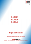
Master’s thesis
Embedded Computer Including Software
for the Intelligent Bird Nesting Box
Bc. Petr Kubizňák
2014
Ing. Pavel Krsek, Ph.D., diploma thesis advisor
Czech Technical University in Prague
Faculty of Electrical Engineering, Department of Cybernetics
Acknowledgement
I would like to thank all people who helped me in any way with this work. Especially
my girlfriend for all her love and everyday care. My family for overall support. Members of this project for great cooperation and supervision. Elnico s.r.o. for providing
development tools and exhaustive technical support. All business partners who helped
with components selection or otherwise participated. And last but not least all developers of free and open source software without which this work would never come
true.
Declaration
I declare that I worked out the presented thesis independently and I quoted all used
sources of information in accord with Methodical instructions about ethical principles
for writing academic thesis.
Prague, Wednesday 7th May, 2014
...........................................
iii
Abstrakt
Tato diplomová práce popisuje návrh a implementaci autonomního kamerového systému, vestavěného do ptačí budky. Tento systém je požadován týmem ornitologů pro
výzkum sýce rousného v jeho přirozeném životním prostředí. Nejprve je navržena sestava hardwarové výbavy, která je následně vyvinuta a vyrobena firmou Elnico s.r.o. dle
TM
R
potřeb systému. Poté jsou vybrány platformy Linux OS○
a Freescale MQX
RTOS
pro paralelní běh na dvoujádrovém mikroprocesoru řídícím hlavní desku. Pro tyto operační systémy jsou vyvinuty aplikace pro pořizování videa a řízení systému, prostředí
je nastaveno pro umožnění přístupu k datům a konfigurování zařízení. Při každém
vniknutí sovy do vletového otvoru budky vzniklý systém zaznamenává video záznamy
ve vysokém rozlišení společně s identifikačními údaji sovy a data o současném stavu prostředí. V závěru jsou prezentovány výsledky prvních experimentů po umístění zařízení
do cílového prostředí na začátku hnízdní sezóny roku 2014.
Klíčová slova
Kamera; monitorování; sovy; vestavný systém; sběr dat
iv
Abstract
This diploma thesis describes design and implementation of an autonomous video
surveillance system embedded in a bird nest-box, needed for research of boreal owl
in its natural environment. First, a custom hardware equipment is proposed and deR
signed. It is then developed and manufactured by Elnico s.r.o. Linux OS○
and Freescale
TM
MQX RTOS operating systems are selected as software platforms running on a dualcore microprocessor in parallel. Video recording and system control applications are
developed and the environment set up to allow data access and system configuration.
The resulted system produces high-definition video records triggered by a bird passing
through the fly-in hole, the bird identification and environment conditions data. Results of the first experiments after deployment in the forest in nesting season of spring
2014 are presented.
Keywords
Camera; Monitoring; Owls; Embedded; Data acquisition
v
České vysoké učení technické v Praze
Fakulta elektrotechnická
Katedra kybernetiky
ZADÁNÍ DIPLOMOVÉ PRÁCE
Student:
Bc. Petr K u b i z ň á k
Studijní program:
Otevřená informatika (magisterský)
Obor:
Počítačové vidění a digitální obraz
Název tématu:
Vestavný počítač a jeho programové vybavení pro inteligentní ptačí budku
Pokyny pro vypracování:
1. Navažte na výzkumný projekt A4M33SVP, který jste řešil v minulém semestru, v němž jste
se s tématem seznámil.
2. Navrhněte a vytvořte systém pro sběr dat s procesorem Freescale Vybrid VF6, který bude
základem inteligentní ptačí budky, a připojte k němu potřebné periferie (dvě kamery, dva
osvětlovače, světelná závora, čtečka RFID, WiFi modul a případně dálkové ovládání).
3. Navrhněte a vytvořte systémový software pro budku nad operačními systémy MQX a Linux.
4. Navrhněte a vytvořte aplikační software inteligentní ptačí budky.
5. Spolupracujte s ornitology z České zemědělské univerzity v Praze při vestavění počítače
do budky a respektujte jejich uživatelské požadavky při vývoji počítače budky.
6. Výsledky zdokumentujte z návrhového i uživatelského pohledu.
Seznam odborné literatury: Dodá vedoucí práce.
Vedoucí diplomové práce: Ing. Pavel Krsek, Ph.D.
Platnost zadání: do konce zimního semestru 2014/2015
L.S.
doc. Dr. Ing. Jan Kybic
vedoucí katedry
prof. Ing. Pavel Ripka, CSc.
děkan
V Praze dne 20. 8. 2013
Czech Technical University in Prague
Faculty of Electrical Engineering
Department of Cybernetics
DIPLOMA THESIS ASSIGNMENT
Student:
Bc. Petr K u b i z ň á k
Study programme:
Open Informatics
Specialisation:
Computer Vision and Image Processing
Title of Diploma Thesis: Embedded Computer Including Software for the Intelligent Bird
Nesting Box
Guidelines:
1. Follow your own research project A4M33SVP, which you solved in the past semester and
which introduced you into the topic.
2. Design and implement data collection system with the processor Freescale Vybrid VF6,
which will be the core of the intelligent bird nesting box, connect necessary peripherals to it
(two cameras, two illuminants, light curtain, RFID reader, WiFi module and potentially
a remote control).
3. Design and implement system sw for the intelligent bird nesting box based on operating
systems MQX and Linux.
4. Design and implement the application sw of the intelligent bird nesting box.
5. Collaborate with ornitlogists from the Czech University of Life Science Prague in
embedding the computer into the nesting box and take into account their user requirements
while developing the nesting box computer.
6. Document your results both from a designer and user point of view.
Bibliography/Sources: Will be provided by the supervisor.
Diploma Thesis Supervisor: Ing. Pavel Krsek, Ph.D.
Valid until: the end of the winter semester of academic year 2014/2015
L.S.
doc. Dr. Ing. Jan Kybic
Head of Department
prof. Ing. Pavel Ripka, CSc.
Dean
Prague, August 20, 2013
Contents
1. Motivation
1
2. Task Formulation
3
3. State of the Art
3.1. Direct Observation . . . . . . . . . . . . . . . . . . . . . . . . . . . . . .
3.2. Continuous Recording . . . . . . . . . . . . . . . . . . . . . . . . . . . .
3.3. Event-based Recording . . . . . . . . . . . . . . . . . . . . . . . . . . . .
5
5
6
7
4. Design
4.1. Hardware . . . . . . . . . . . . . . . .
4.1.1. Control Board . . . . . . . . .
4.1.2. Cameras . . . . . . . . . . . . .
4.1.3. Infrared Lighting . . . . . . . .
4.1.4. RFID Reader . . . . . . . . . .
4.1.5. Light Barrier . . . . . . . . . .
4.1.6. Temperature and Light Sensors
4.1.7. User Interface . . . . . . . . . .
4.2. Software . . . . . . . . . . . . . . . . .
4.2.1. Operating Systems . . . . . . .
MQX RTOS . . . . . . . . . .
Timesys Linux OS . . . . . . .
4.2.2. Libraries . . . . . . . . . . . . .
uEye Library . . . . . . . . . .
MCC Library . . . . . . . . . .
ESL Library . . . . . . . . . .
4.2.3. Processes and Tasks . . . . . .
appmgr . . . . . . . . . . . . .
ueyerec . . . . . . . . . . . . .
ueyeusbd . . . . . . . . . . . .
mcfsd . . . . . . . . . . . . . .
eslAppCtrl . . . . . . . . . . .
appctrl . . . . . . . . . . . . .
irBarrier . . . . . . . . . . . . .
elb149c5m . . . . . . . . . . . .
adc . . . . . . . . . . . . . . . .
sensors . . . . . . . . . . . . . .
hmi . . . . . . . . . . . . . . .
wifi, httpd, ftpd . . . . . . . .
eslLog . . . . . . . . . . . . . .
.
.
.
.
.
.
.
.
.
.
.
.
.
.
.
.
.
.
.
.
.
.
.
.
.
.
.
.
.
.
.
.
.
.
.
.
.
.
.
.
.
.
.
.
.
.
.
.
.
.
.
.
.
.
.
.
.
.
.
.
.
.
.
.
.
.
.
.
.
.
.
.
.
.
.
.
.
.
.
.
.
.
.
.
.
.
.
.
.
.
.
.
.
.
.
.
.
.
.
.
.
.
.
.
.
.
.
.
.
.
.
.
.
.
.
.
.
.
.
.
.
.
.
.
.
.
.
.
.
.
.
.
.
.
.
.
.
.
.
.
.
.
.
.
.
.
.
.
.
.
.
.
.
.
.
.
.
.
.
.
.
.
.
.
.
.
.
.
.
.
.
.
.
.
.
.
.
.
.
.
.
.
.
.
.
.
.
.
.
.
.
.
.
.
.
.
.
.
.
.
.
.
.
.
.
.
.
.
.
.
.
.
.
.
.
.
.
.
.
.
.
.
.
.
.
.
.
.
.
.
.
.
.
.
.
.
.
.
.
.
.
.
.
.
.
.
.
.
.
.
.
.
.
.
.
.
.
.
.
.
.
.
.
.
.
.
.
.
.
.
.
.
.
.
.
.
.
.
.
.
.
.
.
.
.
.
.
.
.
.
.
.
.
.
.
.
.
.
.
.
.
.
.
.
.
.
.
.
.
.
.
.
.
.
.
.
.
.
.
.
.
.
.
.
.
.
.
.
.
.
.
.
.
.
.
.
.
.
.
.
.
.
.
.
.
.
.
.
.
.
.
.
.
.
.
.
.
.
.
.
.
.
.
.
.
.
.
.
.
.
.
.
.
.
.
.
.
.
.
.
.
.
.
.
.
.
.
.
.
.
.
.
.
.
.
.
.
.
.
.
.
.
.
.
.
.
.
.
.
.
.
.
.
.
.
.
.
.
.
.
.
.
.
.
.
.
.
.
.
.
.
.
.
.
.
.
.
.
.
.
.
.
.
.
.
.
.
.
.
.
.
.
.
.
.
.
.
.
.
.
.
.
.
.
.
.
.
.
.
.
.
.
.
.
.
.
.
.
.
.
.
.
.
.
.
.
.
.
.
.
.
.
.
.
.
.
.
.
.
.
.
.
.
.
.
.
.
.
.
.
.
.
.
.
.
.
.
.
.
.
.
.
.
.
.
.
.
.
.
.
.
.
.
.
.
.
.
.
.
.
.
.
.
.
.
.
.
.
.
.
.
.
.
.
.
.
.
.
.
.
.
.
.
.
.
.
.
.
.
.
9
9
10
11
13
14
15
16
16
17
17
19
20
22
22
22
23
24
24
34
35
35
35
35
36
36
36
36
36
36
37
5. Implementation
5.1. Hardware . . . . . . . . . . . . . . . .
5.1.1. Control Board . . . . . . . . .
5.1.2. Camera and Lighting . . . . . .
5.1.3. Light Barrier . . . . . . . . . .
5.1.4. Temperature and Light Sensors
.
.
.
.
.
.
.
.
.
.
.
.
.
.
.
.
.
.
.
.
.
.
.
.
.
.
.
.
.
.
.
.
.
.
.
.
.
.
.
.
.
.
.
.
.
.
.
.
.
.
.
.
.
.
.
.
.
.
.
.
.
.
.
.
.
.
.
.
.
.
.
.
.
.
.
.
.
.
.
.
.
.
.
.
.
.
.
.
.
.
.
.
.
.
.
39
39
39
41
42
42
xi
5.1.5. RFID Reader . . . . . . .
5.1.6. Cover Tamper Button . .
5.2. Software . . . . . . . . . . . . . .
5.2.1. Toolchain . . . . . . . . .
Linux . . . . . . . . . . .
MQX . . . . . . . . . . .
5.2.2. Application . . . . . . . .
Startup . . . . . . . . . .
Recording . . . . . . . . .
5.2.3. Usage . . . . . . . . . . .
Application Data . . . . .
Application Configuration
System Configuration . .
6. Experiments
6.1. Indoor Testing . . . . . . .
6.1.1. Power Consumption
6.1.2. Prey Simulation . .
6.2. Outdoor Testing . . . . . .
.
.
.
.
.
.
.
.
.
.
.
.
.
.
.
.
.
.
.
.
.
.
.
.
.
.
.
.
.
.
.
.
.
.
.
.
.
.
.
.
.
.
.
.
.
.
.
.
.
.
.
.
.
.
.
.
.
.
.
.
.
.
.
.
.
.
.
.
.
.
.
.
.
.
.
.
.
.
.
.
.
.
.
.
.
.
.
.
.
.
.
.
.
.
.
.
.
.
.
.
.
.
.
.
.
.
.
.
.
.
.
.
.
.
.
.
.
.
.
.
.
.
.
.
.
.
.
.
.
.
.
.
.
.
.
.
.
.
.
.
.
.
.
.
.
.
.
.
.
.
.
.
.
.
.
.
.
.
.
.
.
.
.
.
.
.
.
.
.
.
.
.
.
.
.
.
.
.
.
.
.
.
.
.
.
.
.
.
.
.
.
.
.
.
.
.
.
.
.
.
.
.
.
.
.
.
.
.
.
.
.
.
.
.
.
.
.
.
.
.
.
.
.
.
.
.
.
.
.
.
.
.
.
.
.
.
.
.
.
.
.
.
.
.
.
.
.
.
.
.
.
.
.
.
.
.
.
.
.
.
.
.
.
.
.
.
.
.
.
.
.
.
.
.
.
.
.
.
.
.
.
.
.
.
.
.
.
.
.
.
.
.
.
.
.
.
.
.
43
43
43
43
43
45
45
45
46
49
49
51
52
.
.
.
.
.
.
.
.
.
.
.
.
.
.
.
.
.
.
.
.
.
.
.
.
.
.
.
.
.
.
.
.
.
.
.
.
.
.
.
.
.
.
.
.
.
.
.
.
.
.
.
.
.
.
.
.
.
.
.
.
.
.
.
.
.
.
.
.
.
.
.
.
.
.
.
.
.
.
.
.
.
.
.
.
.
.
.
.
53
53
53
54
54
7. Conclusion
61
Bibliography
62
Appendices
A. DVD Content
B. Schematics
B.1. BudkaControl .
B.2. BudkaLighting
B.3. BudkaIRBar .
B.4. BudkaLTS . . .
67
.
.
.
.
.
.
.
.
.
.
.
.
.
.
.
.
.
.
.
.
.
.
.
.
.
.
.
.
.
.
.
.
.
.
.
.
.
.
.
.
.
.
.
.
.
.
.
.
.
.
.
.
.
.
.
.
.
.
.
.
.
.
.
.
.
.
.
.
.
.
.
.
.
.
.
.
.
.
.
.
.
.
.
.
.
.
.
.
.
.
.
.
.
.
.
.
.
.
.
.
.
.
.
.
.
.
.
.
.
.
.
.
.
.
.
.
.
.
.
.
.
.
.
.
71
72
76
77
78
C. Printed Circuit Boards
C.1. BudkaControl . . .
C.2. BudkaLighting . .
C.3. BudkaIRBar . . .
C.4. BudkaLTS . . . . .
.
.
.
.
.
.
.
.
.
.
.
.
.
.
.
.
.
.
.
.
.
.
.
.
.
.
.
.
.
.
.
.
.
.
.
.
.
.
.
.
.
.
.
.
.
.
.
.
.
.
.
.
.
.
.
.
.
.
.
.
.
.
.
.
.
.
.
.
.
.
.
.
.
.
.
.
.
.
.
.
.
.
.
.
.
.
.
.
.
.
.
.
.
.
.
.
.
.
.
.
.
.
.
.
.
.
.
.
.
.
.
.
.
.
.
.
.
.
.
.
79
80
82
84
86
D. Photographs
xii
.
.
.
.
87
Abbreviations
List of standard and few own acronyms and abbreviations.
A5
ACK
ADC
API
ASCII
AVI
bps
BSP
CCD
CMOS
DC
DCT
DDR
ESL
FFS
fps
FTM
FTP
GCC
GDB
GNU
GPIO
GPL
HD
HEX
HTTP
HW
I2 C
ID
IDE
IP
IPC
IR
IRBAR
JPEG
LED
LGPL
M4
MCC
MCFS
MCU
MFS
MPU
NACK
OS
TM
R
ARM○
Cortex -A5
acknowledge
A/D converter
Application Programming Interface
American Standard Code for Information Interchange
Audio Video Interleave
bits per second
Board Support Package
Charge-coupled Device
Complementary Metal–Oxide–Semiconductor
Direct Current
discrete cosine transform
Double Data Rate
Elnico Support Library
Flash File System
frames per second
FlexTimer
File Transfer Protocol
GNU Compiler Collection
GNU Debugger
GNU’s Not Unix
General Purpose Input/Output
General Public License
High Definition
hexadecimal
Hypertext Transfer Protocol
hardware
Inter-Integrated Circuit; also IIC or I2C
identifier
integrated development environment
Ingress Protection
Internet Protocol
inter-process communication
Infrared
infrared light barrier
Joint Photographic Experts Group
Light Emitting Diode
Lesser General Public License
TM
R
ARM○
Cortex -M4
Multi-Core Communication library
Multi-Core File System
Microcontroller Unit; microcontroller
MS-DOS File System
Mcroprocessor Unit; microprocessor
non-acknowledge
operating system
xiii
PC
PCB
PGM
PIT
PSP
PWM
px
RAM
RFID
RFS
ROM
RTC
RTCS
RTOS
SD
SW
SIP
SOM
SPI
TCP
TCP/IP
UART
UI
USB
V4L
WDOG
Personal Computer
printed circuit board
Portable GrayMap
Passive Integrated Transponder
Processor Support Package
Pulse Width Modulation
pixel
Random Access Memory
Radio Frequency Identification
Root File System
Read-Only Memory
Real-time Clock
Real-Time Communication Stack
real-time operating system
Secure Digital
software
System-in-Package
System-on-Module
Serial Peripheral Interface
Transmission Control Protocol
Transmission Control Protocol/Internet Protocol
Universal Asynchronous Receiver/Transmitter
user interface
Universal Serial Bus
Video4Linux
watchdog
Names and Trademarks
List of often used company names and their products and trademarks.
ARM
Cortex
Elnico
Enika
Factory
Freescale
IDS
Linux
MQX
SQM4
Timesys
Windows
xiv
R
ARM○
TM
Cortex
Elnico s.r.o.
Enika.cz s.r.o.
LinuxLink Factory
Freescale Semiconductor, Inc
IDS Imaging Development System GmbH
R
Linux OS○
TM
Freescale MQX
R
SQM4○
Timesys Corporation
TM
R
Microsoft Windows○
OS
1. Motivation
The assignment of this diploma thesis is motivated by the research of Ing. Markéta
Zárybnická, Ph.D. from the Czech University of Life Sciences Prague. She is interested
in geographical variation in breeding and foraging strategy of the Tengmalm’s owl
(Aegolius funereus). The Department of Cybernetics of the Czech Technical University
in Prague, Faculty of Electrical Engineering cooperates at the activity. I was asked
to help the effort in my diploma project by developing and constructing an autonomous
computer system.
My motivation to participate in this project was based on my interest in practical
tasks. I also have the advantage that my father owns company Elnico s.r.o., which
develops and produces embedded electronics. Hence I have access to hi-tech embedded
technologies needed for this project.
My work contributes to a new type of a computerized nest-box enabling the data
acquisition and monitoring of owls nesting in nest-boxes located in their natural environment. The nest-box is hung usually on a tall tree in the forest. It has an own
battery allowing its autonomous operation.
The project requires a video surveillance system embedded in every nest-box to record
a fly in of an owl (typically a male) bringing the prey, usually a small mammal (Microtus
vole or Apodemus mouse) or a bird. The data needed for identification of individual
owls and the type of food supply are recorded.
Such a system has been developed and is described in this thesis. Monitored owls
are equipped by Radio Frequency Identification (RFID) chips. The owl identification
has been based on RFID technology. To identify the type of the prey, the expert
human recognition is required, as there is a high variety within hunted species. For this
sake, a pair of Infrared (IR) High Definition (HD) cameras is used. The first camera
records the entrance hole. The second camera records the nest-box ground. Both
cameras are equipped with an IR flash. The system is further equipped with an IR
optical barrier to detect owls flying in the nest-box and reduce memory and power
requirements by starting the recording only at the time of an event of interest and
stopping it afterwards. Two temperature sensors and one sensor of the ambient light are
included to provide more information about nesting for research purposes. All captured
data is stored permanently on a local filesystem and can be collected through a File
Transfer Protocol (FTP) connection, using a wired local network. The whole system
is powered by one 60 Ah 12 V traction battery which allows for approximately one-week
long autonomous operation of the system.
1
2. Task Formulation
Requirements on the embedded system to be developed are given by the planned research project described in [1]. Authors of the project are researchers from a team
from the Czech University of Live Sciences Prague, Faculty of Environmental Sciences,
Department of Ecology, leaded by Ing. Markéta Zárybnická, Ph.D. They will be further referred to as the ornithologists in this document. The main focus of the project is
posed on the camera surveillance system: “The principal task is to record an owl adult
while bringing the prey into the nest-box and determine the prey species. The male
owl quickly approaches the nest-box opening and in most cases only throws the prey
inside. The secondary task is to monitor a nesting area on the bottom of the nest
box to gain additional information on prey determination, prey decapitation and owl
behaviour (e.g., sibling competition).” This means the system has to contain two cameras, the first recording the fly-in hole and the second recording the nest-box ground.
Since the owls are active at night, a lighting has to be used to provide the cameras sufficiency of light. To prevent disturbance of the birds, source of light invisible to them
shall be used.
To allow for identification of adult owls, each of them is fitted with a Passive Integrated Transponder (PIT) tag of type EM4200, readable by any compatible RFID
reader. The tag should be scanned each time an owl approaches the fly-in hole, not depending on whether it enters or exits the nest-box or just brings a prey. On the other
hand, the reader should not scan codes of birds present inside the box.
To improve the background of the scientific research, the system should be able
to regularly measure temperature inside the nest and outside the nest-box, and exterior
light conditions.
The system shall provide an easily accessible interface allowing to access the produced
data and configure the main application settings. Preferable solution would be a wireless communication on standard TCP/IP protocols. The easily accessible RJ45 socket
with the Ethernet connection might be used as a fall-back variant for case of the Wi-Fi
failure or if the system needs to be mounted before the wireless functionality is implemented.
The output of the system will be:
1. Short video sequences (few seconds long, high frame-rates) of the nest-box fly-in
hole, triggered by the prey delivery events.
2. Longer video sequences (few minutes long, low frame-rates) of the nest-box ground,
triggered by the prey delivery events.
3. RFID codes of the adults delivering the prey, triggered by the prey delivery events.
4. The list of temperatures and ambient light measurements, triggered periodically.
5. All data will be marked with a time-stamp, giving time of its retrieval.
The minimal configurable options will be:
1. Video records lengths, adjustable separately for both cameras.
2. Video records frame-rates, adjustable separately for both cameras.
3. Camera exposures, adjustable separately for both cameras.
3
2. Task Formulation
The system will be powered by a traction 12 V battery, which will be replaced
regularly approximately once in a week. Ideal capacity is between 50 and 60 Ah,
as the dimensions and weight of the battery grow significantly with the capacity, a bigger
battery is hence inadvisable. The system should be designed with respect to minimum
power consumption.
The system will run autonomously and fully automatically, no remote control mechanism is desired. Recorded data will be collected on weekly basis, together with the power
supply replacement.
To achieve requested scientific value of the research, higher number of such intelligent
nest-boxes is needed, the ideal count is twelve. That means that it must be possible
to produce such a number of boxes for a reasonable price, so the components need to be
selected with respect to the cost and availability.
4
3. State of the Art
Nest monitoring is a frequent task in life sciences, particularly in ornithology. It gives
scientists valuable data about population growth, nest attentiveness, parental care, nest
predation, birds’ diet and birds’ behaviour in general. Multiple different approaches
can be taken, each limited by the observation purpose, observed species, financial and
human resources and other constraints.
3.1. Direct Observation
A direct observation is technologically the simplest method used in nest monitoring.
It is based on a periodic visual exploration of nests, either locally or from a distance
(e.g. using binoculars). This method is useful mainly for checking the number of laid
eggs, number of hatched chicks, whether the nest has not been abandoned or predated.
The first main limitation of this method is induced by the monitored species, which
can either nest at inaccessible places (for example rocks) or be particularly sensitive
to human presence.
The second constraint is a limited number of human resources in scientific research,
as periodic checks of a scientifically sufficient number of nests may pose high requirements on time resources. Some researches or programmes try to solve this problem
by popularization of the topic and gaining volunteers which collect the data for them.
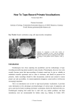
This is for example case of the Michigan Bluebird Society, trying to help and monitor
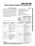
the population of the Eastern Bluebird. Through a large community of so-called landlords (see Fig. 1), they manage to “improve the nesting success of the Eastern Bluebird
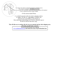
and other native cavity-nesting birds in the state of Michigan” [2], USA.
Figure 1. Landlord performing regular check of a nest-box. From [2].
5
3. State of the Art
3.2. Continuous Recording
A widely used technique is an autonomous video surveillance system equipped with
a camera, a power supply and a data storage or stream. Such systems usually record
one video sequence continuously (typically with a very low frame-rate – time-lapse
video) or record shorter video sequences periodically with time delays.
These systems pose high requirements on the power supply and require either a large
data storage and its periodical replacement, or a sufficient bandwidth of a wired/wireless connection allowing for streaming or downloading the data remotely. One of disadvantages is a high percentage of useless data when there is nothing happening inside
the nest on one hand, and a high amount of potentially valuable events which are not
recorded on the other hand.
This approach has been taken for a research of siblicide in bearded vultures (Gypaetus
barbatus). To observe aggression between two sibling chicks and death of the younger
one, the authors used quite complicated apparatus comprising of two parts: “(1) a nest
monitoring subsystem (camera, microphone, battery with a charge controller and a transmitter together with an antenna), which was supported by a solar panel, and (2) a recording subsystem (antenna receiver, video signal controller and a remote controlled PC
through a GSM modem) that compressed the audio-video signal and provided real time
monitoring.” [3]. The nest monitoring subsystem featured a waterproof colour 640×480
camera with 1/3 inch CCD chip and a 3.6 mm lens with 78∘ wide field of view. It was
scheduled to record one 15 minutes long video shot at the frame-rate of 25 frames per
second (fps) every two hours. The control PC ran the Windows XP operating system.
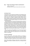
The system was powered by a 100 Ah battery supported by a 75 W solar panel without which the battery would discharge after a period of 4 days. The system structure
is illustrated in Figure 2.
Figure 2. Structure of the video-surveillance system used to monitor a bearded vulture nest.
1–9 Nest subsystem, 10–16 local subsystem, 17 central subsystem. From [3].
6
3.3. Event-based Recording
A much simpler and probably cheaper equipment was used in a research of nest predation of Superb Fairy-wren (Malurus cyaneus) [4]. The recording system was based on
an Apple MacMini computer, controlling and storing data from four waterproof video
cameras Eye Spy World with 1/4 inch Sony CCD sensor. Each camera was powered
by a small 12 V 12 Ah battery and connected to the recording system by a cable.
The system was set to record continuously. To reduce the amount of data, the authors scanned 24 hours of one day only for variation in feeding activity during the day,
as the highest predation risk is during feeding. According to that measure they selected 2-hour period in the morning and 2-hour period in the evening to be examined
thoroughly in all records, the rest was ignored.
3.3. Event-based Recording
Recording systems equipped with event detectors help to automatically separate the interesting data from the rest, simplifying results evaluation and potentially saving power
and storage resources.
One such system has been developed for monitoring nests of Tengmalm’s owl and
is described in [5]. The authors’ functional requirements on the system abilities were:
1. “Observation of movements of the nesting individuals between the nest and the environment.
2. Monitoring the times spent by an individual outwards the nest and in the nest.
3. Identification of the kind and type of prey.
4. Observing behaviour of nestlings and distribution of parental roles in the nesting
period.” [5]
The requirements implied need of a night vision camera, that is a camera sensitive
on IR light, and an IR flash to illuminate the content of the nest-box. The authors
chose a DECAM camera module (SINIT, Czech Republic) equipped with 16 MB data
memory, wireless data communication, two logical inputs and one output for lighting
control. The camera was able to record 1-3 frames per second. The flash was constructed from 24 IR Light Emitting Diodes (LEDs) SFH485-2 with 880 nm wavelength
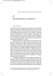
as it was the closest match for expected ideal wavelength of 900 nm.
Figure 3. Conceptual design of device for monitoring nesting of the Tengmalm’s owl. From [5].
As the used camera allowed for storing of a very limited number of pictures (1024, [6]),
the system had to be equipped with a mechanism called motion detector so the camera
7
3. State of the Art
could record only important scenes, filtering out all the rest when there is nothing happening in front of it. The motion detector was in fact an IR optical barrier constructed
from through-beam sensors KS96 (Kotlin, Czech Republic, [7]) with the frequency modulation. The barrier was placed in the fly-in hole so the light beam must be crossed
by the bird entering the box. The sensors could operate on 15-30 V DC.
The system was further equipped with a PIT tag reader device PS02 (Elvis, Czech
Republic) with a circular antenna positioned around the fly-in hole, used to identify
owls fitted with a PIT tag.
The entire system, illustrated in Figure 3, was powered by a 60 Ah 12 V traction
battery which sufficed for 6-8 days operation.
8
4. Design
The event-based surveillance system from [5], described in Section 3.3, became a good
model for the new system being developed. The requirements posed on both systems
were practically the same, so the actual task was to redesign the system from [5] using
the up-to-date technologies, allowing for more functionalities and better performance.
4.1. Hardware
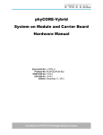
The conceptual design of the system, depicted in Figure 4, is very similar to the design
of the model system, shown in Figure 3. The main difference is in the number of cameras, which is two instead of one. Also, illuminants are controlled directly by the cameras. Important change, not visible from the figure, is that the image data is stored
in a centralized data storage on the control board, so the amount of data is not limited
by the size of cameras internal memories, as it was in case of [5].
Lighting
Lighting
User Interface
Camera
Camera
RFID Reader
Control Board
Interior Sensors
Light Barrier
Battery
Exterior Sensors
Figure 4. Conceptual design of the system hardware. The arrows symbolize the direction
of communication/control.
Completely new items to the scheme are the interior and exterior sensor blocks, which
were not present on the referential design.
The system uses the light barrier as an event detector, too (referred as Movement
detector in Figure 3). Even though it might seem to be redundant since RFID reader
could also be used for the same purpose, experiences with the referential solution have
shown that the reader reliability is not completely satisfiable as the PIT tags sometimes
fail to be scanned.
The following subsections describe briefly each block of the scheme in terms of what
device has been selected and why, without discussing other alternatives as this has
already been done in [8] in terms of the subject A4M33SVP.
9
4. Design
4.1.1. Control Board
The
∙
∙
∙
∙
∙
∙
∙
central block of the system is a control board with the following requirements:
Provides hardware interface to all needed peripherals,
R
(Linux),
allows for running Linux OS○
is powered by a powerful microcontroller (MCU) / microprocessor (MPU),
has a low power consumption,
is well documented,
is guaranteed to be available for several years,
can be acquired for a reasonable price.
No commercially available solution fulfilling all listed requirements was found, so it
was decided to let develop and manufacture a custom board. As a suitable platform,
a new Freescale Vybrid VF6 microprocessor was chosen, bringing all the features diagrammed in Figure 5.
Figure 5. Freescale Vybrid VF6xx microprocessor block diagram. From [9].
The speciality of the microprocessor is its asymmetrical dual-core architecture, conTM
R
sisting of one 500 MHz ARM○
Cortex -A5 (A5) core, designated for running a highTM
R
level operating system (OS), and one 167 MHz ARM○
Cortex -M4 (M4) core primarR
ily for low-level hardware operations. The ARM○
(ARM) architecture is a guarantee
for low power consumption and well-designed hardware. The microprocessor is new,
available generally since January 2014, promising a long time support. And finally,
there exists a processor module SQM4-VF6-W assembled with this MCU. It is manufactured by a Czech company Elnico s.r.o. (Elnico), commercially available from [10].
10
4.1. Hardware
R
SQM4-VF6-W is a product from the SQM4○
(SQM4) solderable processor modules
series. Every device from this series is characterized as a System-on-Module (SOM),
comprising a microcontroller/microprocessor with Double Data Rate (DDR) memory, NAND FLASH memory, Ethernet and Universal Serial Bus (USB) controllers
on a squared module (16 cm2 ), interfaced by so-called RIM connection with 160 pins.
The RIM connection provides 4 variants of assembly, where one of them (Down-pins)
is detachable, designed mainly for development purposes, while the others are solderable, providing a robust and reliable connection between the module and a base board.
The SQM4-VF6-W module, depicted in Figure 6, is comprised of a 256 MB DDR3
SDRAM memory, 256 MB FLASH memory, Dual Ethernet, USB and also an extra
low-power WiFi modem, fulfilling the request on a wireless communication interface.
Figure 6. Photo of the SQM4-VF6-W module, the brain of the intelligent nest-box surveillance
system. From [10].
Using the SQM4-VF6-W module, the development of the custom base board, named
BudkaControl, became much simpler and hence cheaper task than it would be without
it, as it reduced to a simple expansion board of the SOM. The peripheral scheme
of the base board, illustrating the structure and assignments of the board peripherals
to the peripheral devices, is depicted in Figure 7. The peripheral devices are described
in the following subsections.
4.1.2. Cameras
The most attention in selection of peripheral devices was paid to the digital cameras,
being the most important and expensive part of the system. It was decided to buy
two monochrome industrial cameras UI-1541LE by IDS Imaging Development System
GmbH (IDS), depicted in Figure 8. This type has the following features:
∙ Monochromatic CMOS sensor 1/2",
∙ resolution 1280×1024 px,
∙ maximum 25 fps,
∙ USB 2.0 interface,
∙ 1× external flash output,
∙ 1× external trigger input,
∙ 2× external GPIO,
∙ 1× external I2 C bus,
∙ free C/C++ API, Linux drivers and demos available.
11
4. Design
BudkaLTS
BudkaLTS
BudkaLighting
t°
t°
AR4100
USB
UI-1541LE
BSM4016S12
BudkaLighting
Ethernet
SQM4-VF6-W
UART
I2C
ELB149C5M
BudkaControl
GPIO
SD-micro
Power
Supply
UI-1541LE
BSM6016S12
BudkaIRBar
12V
Figure 7. Peripheral scheme of the control board BudkaControl, depicting board peripherals
assigned to peripheral devices.
Figure 8. Photo of the UI-1541LE monochrome industrial camera. From [11].
12
4.1. Hardware
Each camera should monitor different scene, implying different viewing angles, as
illustrated in Figure 9. For this sake, different lenses were mounted on each camera.
The fly-in camera was equipped by a lens BSM4016S12 (𝑓 = 4 𝑚𝑚, 96∘ horizontal field
angle, S-Mount) to fulfil requirement of viewing the whole front side from the fly-in
hole to the box ground, and the ground camera was equipped by a lens BSM6016S12
(𝑓 = 6 𝑚𝑚, 65∘ horizontal field angle, S-Mount) allowing for viewing the bottom half
of the box. Both lenses are distributed by IDS, too.
8
53°
8
75°
24
20
20
Figure 9. Approximate cameras viewing angles, derived from expected box dimensions (in
centimetres). Violet: The fly-in camera and its required field of view. Green: The ground
camera and its required field of view.
4.1.3. Infrared Lighting
The camera chip is not covered by any IR-cut filter, allowing for sensitivity on the IR
light. Graph of the chip sensitivity with respect to the light wavelength is depicted
in Figure 10. In the wavelength range of 700-900 nm, the chip sensitivity falls steeply
with the growing wavelength, with only approximately 23% of full sensitivity at 900 nm
wavelength. For this reason, the wavelength of the camera lighting should be rather
close to 800 nm where the efficiency is much higher (about 40%).
Thanks to the external flash output of the UI-1541LE cameras, the lighting can be
controlled right from the cameras. It was decided to develop a special board named
BudkaLighting, implementing the infra-red lighting functionality. As the cameras have
no covering, the board was designed to be directly connected to the camera and covered
together in one box, protected on level at least IP54 (dust and partial water protection).
As the light source, TSHG5510 IR LED by Vishay was picked. Main reasons for
this type were its peak wavelength 𝜆𝑝 = 830 𝑛𝑚 and a high angle of half intensity
𝜙 = ±38∘ , promising a uniform illumination of the whole scene. Graphs of the relative
radiant power/intensity with respect to the wavelength and angular displacement are
shown in Figure 11. More technical information can be found in [12].
13
4. Design
Figure 10. UI-1541LE-M-GL camera chip sensitivity on different light wavelengths. From [11].
Figure 11. TSHG5510 HighSpeed Infrared Emitting Diode. Left: Relative Radiant Power vs.
Wavelength. Right: Relative Radiant Intensity vs. Angular Displacement. From [12].
4.1.4. RFID Reader
Monitored owls are tagged with an RFID chip EM4200. It can be scanned by various commercially available RFID readers. The product ELB149C5M by Seeed Studio
(see Figure 12) was found at [13] to be appropriate for this task. First it has relatively
low power consumption (approx. 30 mA / 5 V), second it has a modular construction
with a simple communication interface (UART, baud rate 9600 bits per second (bps),
TTL output [14]) so it can be easily integrated into the system, and finally it is available
for a very reasonable price.
The module is distributed with an external antenna which cannot be used though.
A circular antenna around the fly-in hole, similar to the one used in the referential design
(see Section 3.3), needed to be manufactured. Its dimensions are depicted in Figure 13.
14
4.1. Hardware
Figure 12. RFID chip reader ELB149C5M. From [13].
Figure 13. Custom RFID antenna dimensions requirements. Distances are in millimetres.
(Edited drawing by the ornithologists.)
4.1.5. Light Barrier
The light barrier is an important part of the system functioning as the event trigger.
It is a device consisting of one transmitter and one receiver. Transmitter is typically
a LED, usually emitting an IR light. Receiver is located opposite to the transmitter and
detects whether the space between both parts is clean, i.e. the light excites the receiver,
or the beam is disrupted by a non-transparent object. The light is usually modulated
by a periodic signal of a defined frequency, all other frequencies are filtered by the
receiver, providing the high robustness against ambient light (sunlight, artificial light
sources of different frequencies).
There are plenty of commercial products available on the market, being used for
example for gate control or toilets flushing. These devices have usually a relatively
high power consumption, big packaging and high cost. The majority of them (perhaps
most of them) are also designed for too high voltage, often 230 V.
For these reasons, it was decided to develop and manufacture a custom light barrier
on a board named BudkaIRBar. The receiver (TSSP58038 by Vishay, technical specification in [15]) is designed for 38 kHz pulses of IR light with the highest sensitivity
15
4. Design
at 950 nm, and can be powered from 2.5 V to 5.5 V. The transmitter (TSAL5100
by Vishay, technical specification in [16]) is a simple IR LED with peak wavelength
𝜆𝑝 = 940 𝑛𝑚 and a narrow beam (angle of half intensity: 𝜙 = ±10∘ ). The output signal of a required frequency needs to be generated by an external source. Pulse Width
Modulation (PWM) peripheral of the processor will be used for that.
The board is designed to be placed in a groove milled in the front side of the nest-box,
as illustrated in Figure 14. The board has a special shape so it goes around the fly-in
hole and the light beam crosses the hole horizontally in the middle.
Figure 14. Illustration of the light barrier design and its placement in a groove milled
in the front side of the box.
4.1.6. Temperature and Light Sensors
Interior and exterior sensors are designed as separate tiny boards named BudkaLTS.
Both boards contain the temperature sensor (MCP9804 by Microchip, technical specification in [17]) communicating on Inter-Integrated Circuit (I2 C) bus. In addition,
the exterior sensors board features a 12-bit I2 C A/D converter, processing analog input
from a photocell, implementing a light sensor. These parts are not placed on the interior
sensors board.
The exterior sensors board is designed to be built in a nest-box side in such a way
the photocell is in the box exterior. The interior sensor is not planned to be fixed
on any place; on the contrary it should be on a loose cable so the ornithologists can
place it for example amongst eggs and measure the temperature directly in the nest.
4.1.7. User Interface
According to the requirements, the user interface is designed to be realized by two hardware interfaces – Ethernet (a wired network) and WiFi (a wireless network). All needed
controllers are implemented on the SQM4-VF6-W module. In case of Ethernet, only
the RJ45 connector needs to be placed on the base board. The WiFi is implemented
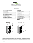
by the Qualcomm-Atheros AR4100P chip.
The AR4100P is a small, single stream, 802.11 b/g/n WiFi System-in-Package (SIP)
solution. It is primarily designed for applications hosted by low-resource microcon16
4.2. Software
trollers that send infrequent data packets over the network. The system features extralow power consumption, balanced by a lower throughput [18].
The chip is placed on the bottom side of the SQM4-VF6-W module, as shown in Figure 15. The module also features a tiny U.FL male connector on the top side, as visible
in Figure 6. That can be used to connect the external WiFi antenna.
Figure 15. Bottom side of the SQM4-VF6-W SOM, with the AR4100P WiFi SIP
by Qualcomm-Atheros.
4.2. Software
The main goal of this thesis is to develop an application serving all the hardware
described in Section 4.1 and implementing all the functionalities described in Chapter 2.
The application has been named Birdhouse.
The most general application flowchart is depicted in Figure 16. After powering on
the device, the system boots, and depending on the daytime, it enters either a Sleep
mode with most of the peripheral hardware powered off (light barrier, RFID reader,
cameras), or a Ready mode, with all its hardware powered on.
In the Sleep mode, only the temperature and light sensors are periodically read out
with a predefined time period. In the Ready mode, besides the periodical sensors readouts, recording operation can be triggered by a disruption of the light barrier. When
that happens, firstly a short video sequence is recorded by the fly-in camera (further
referred to as the door camera, D), then a longer sequence is recorded by the ground
camera (further referred to as the floor camera, F ). RFID identification is performed
in parallel with the camera recording.
A real design of the application is much more complex though and is discussed
on multiple levels – operating systems, libraries and processes/tasks. Its hierarchy
is depicted in Figure 17.
4.2.1. Operating Systems
There is a wide selection of operating systems used in embedded. Most of them are
real-time operating systems, i.e. operating systems meeting real-time requirements.
Such systems guarantee the response within strict time constraints, often referred to
17
4. Design
Power On
Boot
No
Is night?
Yes
Sleep
No
Readout
scheduled?
Yes
Read out sensors
Ready
No
Barrier
disrupted?
Yes
Record [D]
Identify
Record [F]
Figure 16. General application flowchart. The blue blocks are executed by the M4 core, the red
blocks by the A5 core.
as deadlines. Depending on the consequences of missing the deadline, real-time systems
are divided into three groups:
∙ “Hard: Missing a deadline is a total system failure.
∙ Firm: Infrequent deadline misses are tolerable, but may degrade the systems quality of service. The usefulness of a result is zero after its deadline.
∙ Soft: The usefulness of a result degrades after its deadline, thereby degrading
the system’s quality of service.” [19]
The Birdhouse application can be categorized as a soft real-time system, posing realtime requirements on the delay between the light barrier disruption and start of recording by the door camera. The requirements were not defined specifically, but they can
be derived from the need to record at least 3 frames of the prey by the door camera
before it falls on the ground, i.e. out of the camera view. As the prey occurrence takes
about 500 ms, the recording must start with respect to this duration and the camera
frame rate. From the user point of view, the best would be if the recording started
18
Applications
Tasks
uEye
ESL
Kernel
BSP/PSP
BSP/PSP
ARM Cortex M4
ARM Cortex A5
Freescale Vybrid VF6
Processor
MCC
Operating System
Standard Libraries
Stacks
Kernel
Bash Scripts
Application
4.2. Software
Peripherals
Figure 17. The system software block diagram from the HW/OS point of view. All application
specific parts, implemented in terms of this work, are labelled in underlined bold font.
“immediately”, i.e. the system should minimize the time delay between the disruption
event and recording start.
The freedom of selection in this application has been limited from the beginning
though. The uEye library, needed to access and control the cameras (see 4.2.2), is
available only in the binary form for Windows PC and Linux under a limited number
of architectures. Use of the latter operating system on the A5 core is hence inevitable.
Analogously, to communicate with the AR4100 WiFi SIP (see Section 4.1.7), an operating system supported by the wifi driver has to be selected. From the sparse list
TM
of supported operating systems, Freescale MQX
(MQX) real-time operating system (RTOS) was picked.
MQX RTOS
TM
Freescale MQX
is a real-time operating system provided by Freescale Semiconductor, Inc (Freescale). It is free to use with all Freescale MCUs and MPUs. It features
a lightweight component-based microkernel with a highly customizable architecture, as
depicted in Figure 18. It is a multi-platform OS with a minimal footprint of necessary
components (Core), allowing to be used on most Freescale-based devices. The kernel
includes a real-time, priority-based pre-emptive scheduler allowing for real-time multitasking and fast interrupt handling, extensive inter-task communication and synchronization facilities [20].
19
4. Design
TM
Figure 18. Freescale MQX (MQX) real-time operating system (RTOS) highly customizable
microkernel architecture. From [20].
Besides the kernel, MQX contains also Processor Support Packages (PSPs) for all
supported platforms, Board Support Packages (BSPs) for various development boards,
optional software stacks, services and frameworks (see fig. 19):
∙ FFS – Flash File System, low-level flash drivers with wear-levelling.
∙ MCC – Multi-Core Communication library, efficient inter-core MQX-to-MQX or
MQX-to-Linux communication subsystem.
∙ MFS – Embedded MS-DOS File System.
∙ RTCS – Real-Time Communication Stack, a TCP/IP stack implementation.
∙ Shell – A lightweight command-line environment.
∙ USB – Universal Serial Bus host/device stack.
MQX further contains tens of examples and a pretty quality documentation. Together with referential development kits and quite good support, MQX became the best
choice of all available operating systems runnable on the M4 core. Also availability of
Multi-Core Communication library (MCC) and Elnico Support Library (ESL) is a great
advantage, as described in Section 4.2.2.
Timesys Linux OS
Linux is not a real-time operating system by design. There are some Linux kernel
modifications or extensions, for example PREEMPT_RT [21], but I have no experiences
with these extensions. Since the application belongs to the soft real-time category with
no critical impacts in case of failure, this direction was not further considered.
Seeking for a Linux distribution, it was evident that a custom one must be built,
as the kernel configuration and BSP must be adjusted according to the custom board.
It was logical to choose the LinuxLink framework by Timesys Corporation (Timesys)
for a bunch of reasons.
First, Timesys is “a trusted source of embedded Linux” [22], with deep experience
in real-time Linux. They develop LinuxLink, a software development framework for
configuration, patching, building and maintenance of an open source Linux platform.
20
4.2. Software
Figure 19. Block diagram of a software solution based on the MQX RTOS. From [20].
“It includes a Linux kernel, GNU toolchain, packages, libraries and development tools.
All Linux platform components and updates are open source and are provided through
the LinuxLink Factory custom platform builder” [23] (see fig. 20 for the typical LinuxLink flow). They also provide documentation and support. They are a partner
of Freescale, supplying Linux PSPs for the Freescale’s processors and BSPs for their
development boards.
Figure 20. Typical LinuxLink framework flow. From [22].
Second, although LinuxLink is a commercial service, a long-term professional license
is granted to every customer who purchased TWR-VF65GS10 [24], the Vybrid development board by Freescale. Elnico, the manufacturer of the SQM4-VF6-W Vybrid
21
4. Design
module (Figure 6) and developer of the BudkaControl board (design described in Section 4.1.1, realization in 5.1.1), is a LinuxLink licensee and can provide custom Linux
configuration and build through this tool.
And finally, Timesys develops and distributes the mcc-kmod package [25], a Linux
kernel module providing communication with the MQX MCC library (see section 4.2.2).
That is, using the Linux by Timesys, we can get well prepared and supported Linux
distribution allowing communication with MQX running on the second core.
4.2.2. Libraries
Selection of the essential software libraries used by the application is a fundamental
task which has to be done in the software design phase. In this case, uEye, MCC and
ESL libraries belong to such category.
uEye Library
uEye is a software library for UI cameras control, provided by their manufacturer,
IDS Imaging Development System GmbH. It contains drivers with a daemon process,
Application Programming Interface (API), examples and few utilities. It provides
the only way to access and control the cameras as they do not comply with common
video standards like Video4Linux (V4L).
The library is proprietary and is distributed only in the binary form, the source
files are not available. Use of the library (and thus the UI cameras) hence depended
TM
R
on availability of suitable binaries for the ARM○
Cortex -A5 platform. No such library distribution existed. Nevertheless, after some tries it appeared that a distribution
for BeagleBoard can be used. BeagleBoard is an open-source hardware computer with
an ARM Cortex A8 processor [26]. The A8 and A5 cores have the same architecture
ARMv7-A, so they feature the same instruction set [27]. For this reason, the binaries
built for BeagleBoard are compatible with the A5 core on Vybrid VF6, even though
they are not optimized for use on this MPU. The latest uEye library distribution for
BeagleBoard (uEye version 3.90) was downloaded from [28], up-to-date PC binaries
and documentation is available from [29].
The library features a C/C++ API, providing a high number of functions, briefly:
∙ Preparing image capture – camera opening and closing, querying library and camera information, image buffer allocation and freeing.
∙ Camera configuration – getting and setting camera pixel clock, exposure, gain,
gamma, saturation, frame-rate, image preprocessing, . . .
∙ Capturing – capture mode setting, capture control, event handling.
∙ Storing – single frames loading and saving to the file system.
∙ External communication – General Purpose Input/Output (GPIO) and flash control, I2 C communication.
MCC Library
The Multi-Core Communication library (MCC) is a subsystem which enables communication of applications running on different cores of multicore processors. Each
communication channel consists of two message queues stored in the shared RAM,
signalization is realized by interrupts and exclusive access by hardware semaphores.
That ensures a lightweight and fast communication with simple blocking/non-blocking
send/receive API calls [30].
22
4.2. Software
The library supports MQX and Linux operating systems, allowing for either MQXto-MQX or MQX-to-Linux communication. It is developed by Freescale and Timesys.
In MQX, it is shipped as part of the MQX distribution. In Linux, the library can be
fetched from a repository. It operates in the kernel space, being injected to the Linux
kernel as the kmod-mcc kernel module developed by Timesys.
This communication layer is a fundamental part of the Birdhouse project, allowing
for dual-core MQX-Linux implementation.
ESL Library
The Elnico Support Library (ESL) is a middleware framework built on top of MQX
version 4. It is developed by Elnico as a support software for their Kinetis and Vybrid
processor modules. It is a modular, highly configurable multiplatform library, simplifying use of often used functionalities and enabling quick composition of new applications
from the library modules as follows:
∙ “appctrl – application control mechanisms,
∙ cfg – config files parser and writer,
∙ crc – cyclic redundancy check,
∙ fs – useful filesystem functions,
∙ gpio – GPIO interrupts demultiplexer,
∙ i2c – I2C communication,
∙ log – logging task,
∙ mcfs – virtual multicore filesystem,
∙ nand – NAND flash file system,
∙ rtc – real time controller,
∙ sd – SD card,
∙ spi – SPI bus control,
∙ spimem – SPI memory control,
∙ wifi – Atheros wifi control.” [31]
Use of the library can significantly simplify and accelerate the target application
development, reducing the application code size as Figure 21 illustrates.
Most of the library modules are used in this project, namely appctrl, cfg, gpio, i2c,
log, mcfs, rtc and wifi.
appctrl is a simple module implementing task eslAppCtrl. Its purpose is to start all
the other application tasks and control their run. In the version used in the Birdhouse
application (1.004, not publicly available at the time of writing this document), its
function is limited to simply starting all the other tasks in a defined order.
cfg is an implementation of a very simple configuration files processor. Configuration
files are needed to keep the user settings, e.g. camera exposure times.
gpio realizes a simple interrupt demultiplexer. On Vybrid, there is only one interrupt
vector for each GPIO port. When there are more then one GPIOs from the same port
used, the application needs to check on which pin from the port the interrupt originated.
That is done by this module.
i2c module is a set of functions for accessing the I2 C peripheral, enforcing mutual
access to each channel. The I2 C peripheral is used to communicate with the sensors
on the BudkaLTS board (see Section 4.1.6).
log implements logging functions and a task responsible for writing the log messages
to a defined location (a UART standard output and/or a file on a file system). It collects
logging messages from both the library and the application.
23
4. Design
Figure 21. Elnico Support Library middleware diagram. From [31].
mcfs is a virtual multi-core file system used to access a Linux file system from MQX.
It installs a file system into MQX and communicates using MCC with a Linux daemon
running on the second core and actually executing the read/write commands. Since
the whole dual-core system disposes of only one non-volatile memory storage (Secure
Digital (SD) card), it has to be shared by both cores, i.e. by both operating systems.
One solution would be to use hardware semaphores to synchronize access to the device, which would probably require modifications in the Linux kernel. Multi-Core File
System (MCFS) gives an alternative way to share the medium as described previously
in this paragraph, and is used in this application for all MQX file operations.
rtc is a simple set of functions for date/time operations, e.g. generating time stamps
for log and other purposes.
wifi is a complex module containing the driver for the AR4100 Atheros wifi SIP.
On the top of the driver and the MQX TCP/IP stack, access point and managed modes
are implemented. This module can be used for the WiFi human-machine interface.
4.2.3. Processes and Tasks
From the processes and tasks point of view, the application gets pretty complicated.
The overall processes/tasks diagram is depicted in Figure 22.
In MQX, the whole application is formed of a single executable binary, containing
the OS kernel, drivers and user program. Individual subprograms are implemented similarly to threads, but are called tasks and play the role of processes in the Linux/Windows
terminology. For this reason, MQX tasks and Linux processes in Figure 22 are shown
on the same level of abstraction. They are described in the following subsections.
appmgr
appmgr is the name used for two executable entities – an MQX task appmgrM and
a Linux process appmgrL . They form two sides of the main core of the Birdhouse
application. They are the only executable entities which perform the inter-core communication (if not counting the MCFS subsystem), forming the application’s backbone.
24
4.2. Software
MQX MCC Linux
eslAppCtrl
adc
appctrl
1.
a
b
2.
a
b
3.
a
b
4.
a
b
sensors
ueyeusbd
postprocessor
irBarrier
appmgr(M)
appmgr(L)
elb149c5m
hmi
eslLog
ueyerec(D)
ueyerec(F)
wifi
http
mcfs:
mcfsd
/
ftp
Figure 22. Birdhouse application processes/tasks communication diagram. In MQX, each
block represents one task. In Linux, each block represents one process. Grey blocks represent
third-party tasks/processes. Tasks labelled in grey italics were not implemented. Legend:
1. a starts b. 2. Client-server communication, a being a client of b. 3. a controls b. 4. a sends
data to b.
appmgrM plays the superior role in the communication based on the client-server
model, appmgrM being the client and appmgrL being the server. The communication
protocol for the three most important operations is defined in Table 1. The client
always starts the communication by sending a message of given type. Each message
can further contain iParam, iParam2, iParam3 and uParam parameters. WAKEUP,
SLEEP, RECORD, RECORD_FINISH and ACK message types and MCC_OK and
MCC_ERROR return codes are defined.
appmgrM is basically an event processor which after initialization cycles in an endless
loop, as depicted in Figure 23. There are three main event types: SLEEP, WAKEUP
and RECORD. After an event is detected, appropriate operation is executed. Should
any of the operations fail, the whole processor is reset immediately and the application
must start again from the beginning, recovering from the failure state.
SLEEP and WAKEUP events are triggered by a periodic timer. They switch the application to the READY mode at predefined evening time, and to the SLEEP mode
at predefined morning time. The subsequent operations are depicted in Figures 24 and
25. Both operations are similar – appmgrM sends corresponding message to appmgrL ,
waits for reply and powers on/off the RFID and infrared light barrier (IRBAR) devices
(through elb149c5m and irBarrier tasks).
25
4. Design
Message
WAKEUP
SLEEP
RECORD
Protocol Description
The server powers-up the USBs and starts ueyerec for both the door and
floor camera. It replies with ACK where iParam is set to the operation
result – MCC_OK on success, MCC_ERROR if something failed. In
the case of failure, uParam contains additional information about which
camera experienced problems. The server remains in the READY mode
anyway. It is responsibility of the client to take appropriate action to fix
the state.
The server stops ueyerec for both the door and floor camera and powersdown the USBs. It replies with ACK where iParam is set to the operation result – MCC_OK on success, MCC_ERROR if something failed.
uParam then contains additional information about which camera experienced problems.
To create a record of two video sequences and accompanying data, client
sends a RECORD message with data triplet [interier temperature], [exterier temperature], [exterier light] stored in iParam, iParam2, iParam3.
If the server is ready (i.e. it is in the READY mode and not busy), it immediately replies by ACK with iParam set to MCC_OK and starts recording
the video. In a short time period, the client sends a RECORD_FINISH
message, with iParam set to MCC_OK and uParam set to detected RFID
code, or with iParam set to MCC_ERROR if no RFID code was detected.
The server replies after finishing the recording job by ACK with iParam
set to either MCC_OK or MCC_ERROR depending on the operation
result. If the server is not ready when the RECORD message is received,
it replies by ACK with iParam set to MCC_ERROR and the transaction
ends, client does not send more messages.
Table 1. appmgr inter-core client-server communication protocol. The communication is always initiated by sending a message of type in the left column from appmgrM to appmgrL .
The SET_READY operation is more complicated by taking several trials before
giving up, as the remote operation labelled as A5_SET_READY is not fully reliable
due to USB issues. That is not a pleasant solution but it is acceptable, as this operation
is not time-critical.
The RECORD event is triggered by disruption of IRBAR, handled by the irBarrier task, and is only valid when the system is in the READY mode. The operation
has two steps, as shown in Figure 26. First appmgrL is notified about the event so
the camera recording starts. appmgrL replies immediately so appmgrM can continue
operation. It waits for a predefined delay and then retrieves last scanned RFID code
from the elb149c5m task. Depending on the age of the code (as every code is equipped
with a timestamp), it is used or thrown away. Then a RECORD_FINISH message
is sent to appmgrL and execution stops until a reply is received. It is responsibility
of appmgrL to store all the records to the permanent storage.
appmgrL is the main process on the Linux side of the application. It firstly starts
the mcfsd process needed for the MCFS file system, and then it enters the infinite
message loop, as depicted on a flowchart in Figure 27. It is an interlink between
MQX (appmgrM ) and the recording processes, instances of ueyerec. It plays a role of
a server in the MCC communication (with appmgrM ) and a client in the inter-process
communication (IPC) with ueyerec.
26
4.2. Software
Start
Reset
Initialization
Service WDOG
Yes
SLEEP event?
SET_SLEEP
No
Yes
WAKEUP event?
SET_READY
No
Yes
RECORD event?
No
RECORD
Yes
No
Success?
Figure 23. appmgrM task flowchart. SET_SLEEP, SET_READY and RECORD operations
are depicted in Figures 24, 25 and 26.
The infinite loop realizes the server role for appmgrM . When a message is received,
appmgrL executes appropriate operation including a client communication with ueyerec.
These operations are depicted in Figures 28 and 29.
In A5_SET_READY operation (Figure 28), appmgrL powers on both USB channels and tries to run two instances of ueyerec, each for one camera. This operation,
labelled as START_UEYEREC, first involves forking and running a new process – instance of ueyerec. This process is given an inter-process communication (IPC) queue
identifier (ID) of appmgrL . To allow for bidirectional communication, appmgrL needs
to know IPC queue ID of the new task - that is done during a three-step handshake
illustrated in Figure 30. First ueyerec sends a HANDSHAKE1 message with ID of its
IPC queue. appmgrL replies by HANDSHAKE2 message with system process ID of the
ueyerec process, which replies by an empty HANDSHAKE3 message, playing a role of
simple acknowledge (ACK). By that, the IPC communication between these two tasks
is established. appmgrL then instructs ueyerec to get to the Ready mode by opening, activating and configuring the camera (messages OPEN, ACTIVATE, SET_EXPOSURE
and SET_GAIN ). Full collection of used IPC messages and their parameters is listed
in Table 2.
27
4. Design
SET_SLEEP
Yes
Is Ready?
send SLEEP
A5_SET_SLEEP
No
recv ACK
Success?
No
Yes
power off RFID, IRBAR
return
Figure 24. SET_SLEEP operation flowchart, executed by appmgrM . Violet blocks represent
MCC communication. The red block is illustration of corresponding A5 operation (appmgrL ).
In A5_SET_SLEEP operation (Figure 28), appmgrL stops both instances of ueyerec
and powers off both USB channels. Stopping the ueyerec processes involves a sequence
of IPC messages (DEACTIVATE, CLOSE, QUIT ), followed by a forced kill of the process if it does not terminate as requested.
A5_RECORD_START operation (Figure 29) simply checks that appmgrL is ready
for recording. A5_RECORD_FINISH (Figure 29) is also trivial, it only outputs data
received from appmgrM (sensor data and RFID code) to a file.
More complicated is the A5_RECORD operation (Figure 29). It first commands
the ueyerec process handling the door camera (ueyerecD ) to record a video sequence
of preset parameters (duration, framerate), and then it does the same for the ueyerec
process handling the floor camera (ueyerecF ) with different parameters.
The IPC communication hidden behind this “command” is following: appmgrL sends
a LIVE message with requested duration and frame-rate of the video record to be
captured, ueyerec replies by SUCCESS message, appmgrL sends a text message with
output filenames format, ueyerec records the video sequence and replies by SUCCESS
message.
28
4.2. Software
SET_READY
Yes
Is Sleep?
i=0
No
No
i<TRIALS?
Yes
send WAKEUP
i=i+1
A5_SET_READY
recv ACK
Success?
No
Yes
power on RFID, IRBAR
SET_SLEEP
return
Figure 25. SET_READY operation flowchart, executed by appmgrM . Violet blocks represent
MCC communication. The red block is illustration of corresponding A5 operation (appmgrL ).
29
4. Design
RECORD
Yes
Is Ready?
send RECORD
A5_RECORD_START
No
recv ACK
No
Success?
Yes
A5_RECORD
RFID_AFTER_DELAY
get RFID
send RECORD_FINISH
A5_RECORD_FINISH
recv ACK
return
Figure 26. RECORD operation flowchart, executed by appmgrM . Violet blocks represent MCC
communication. The red blocks are illustration of corresponding A5 operations (appmgrL ).
30
4.2. Software
Start
Initialization
Start mcfsd
A5_RECORD
Yes
No
recv message
send ACK
Success?
Yes
msg==RECORD?
A5_RECORD_START
No
msg==
RECORD_FINISH?
Yes
A5_RECORD_FINISH
No
Yes
msg==SLEEP?
A5_SET_SLEEP
No
Yes
msg==WAKEUP?
A5_SET_READY
No
send ACK
Figure 27. appmgrL task flowchart.
Violet blocks represent MCC communication.
A5_SET_SLEEP, A5_SET_READY, A5_RECORD_START, A5_RECORD and
A5_RECORD_FINISH operations are depicted in Figures 28 and 29.
31
4. Design
A5_SET_SLEEP
A5_SET_READY
No
No
Is Ready?
Is Sleep?
Yes
Yes
STOP_UEYEREC(D)
power on USBs
STOP_UEYEREC(F)
START_UEYEREC(D)
power off USBs
START_UEYEREC(F)
return
return
Figure 28. A5_SET_SLEEP and A5_SET_READY operations, executed by appmgrL . Orange blocks involve IPC communication with ueyerec.
A5_RECORD
A5_RECORD_START
No
RECORD_UEYEREC(D)
A5_RECORD_FINISH
output data
Is Ready?
Yes
RECORD_UEYEREC(F)
return
success
return
failure
Figure 29. A5_RECORD_START, A5_RECORD and A5_RECORD_FINISH operations,
executed by appmgrL . Orange blocks involve IPC communication with ueyerec.
32
4.2. Software
Message
QUIT
OPEN
CLOSE
ACTIVATE
DEACTIVATE
LIVE
SET_EXPOSURE
SET_GAIN
HANDSHAKE1
HANDSHAKE2
HANDSHAKE3
SUCCESS
FAILURE
Parameters
–
–
–
–
–
duration,
framerate
exposure
gain
IPC queue ID
process ID
–
–
–
Description
Quit the application.
Open the camera.
Close the camera.
Wakeup the camera from standby.
Sleep the camera to standby.
Capture a video of specified parameters.
Set camera exposure time.
Set camera chip gain.
First handshake message (sent by server).
Second handshake message (sent by client).
Last handshake message (sent by server).
Operation success (sent by server).
Operation failure (sent by server).
Table 2. Inter-process communication messages between appmgrL and ueyerec processes.
HANDSHAKE1(queue_id)
HANDSHAKE2(process_id)
HANDSHAKE3()
OPEN()
SUCCESS()
ACTIVATE()
SUCCESS()
SET_EXPOSURE(exposure)
SUCCESS()
SET_GAIN(gain)
SUCCESS()
Figure 30. Inter-process protocol illustration on case of operation START_UEYEREC. Yellow
messages are sent from ueyerec to appmgrL , the red ones in the opposite direction.
33
4. Design
ueyerec
ueyerec (the name comes from UI recorder) is the only program designed to access and
control the cameras (or better to say the camera; two program instances are needed
to control two cameras). It serves as a server for appmgrL . It provides commands
to open, configure and close a camera, and to take a snapshot or record a sequence
of video frames.
The program again cycles in a message queue, as depicted in Figure 31. Messages
are received first from the user interface (UI), second from the connected camera, and
third from a periodic timer.
data flow
Initialization
messages flow
Camera
user
input
message loop
Timer
user
output
Filesystem
Figure 31. Simplified ueyerec functionality diagram illustrating data and messages flow inside
the program.
On the target device, ueyerec UI stands for the IPC communication with appmgrL ,
being a source of commands corresponding to the camera control messages from Table 2.
The camera produces several types of events, which are then translated to messages
handled by the message loop. In the used camera mode (Software Trigger mode, see Figure 32), the considerable events are TRIGGER and FRAME events. The TRIGGER
event is emitted when the camera is ready for the next frame capture, i.e. when the last
frame was already captured and transferred, but not preprocessed by the uEye library
API. Last frame preprocessing (generally e.g. color conversion) and new frame capturing can be done in parallel, as both operations run on different hardware. When
the frame is also preprocessed by the API and is ready for the application processing,
the FRAME event is triggered.
The events need to be translated by separate threads to the messages recognized
by the main message queue. When the corresponding FRAME message is received,
ueyerec simply stores the captured frame to the file system as an image file, as the uEye
library under Linux does not provide direct output in a video format (e.g. Audio
Video Interleave (AVI)). New frame capture is initiated after the file has been saved,
since this sequential approach saves memory (only one image buffer is needed) and
prevents the code from potential bugs, while providing high enough frame-rate (for this
application).
34
4.2. Software
Figure 32. uEye camera software trigger mode flow diagram. From [32].
To allow for capturing frames with a requested frame-rate, new capture cannot be
initiated right after the application is ready for it, but it needs to wait for a synchronization message from a periodic timer. The timer sends two types of messages –
first the periodic frame ticks, and second the end of capture message to ensure proper
capture length.
When the whole image sequence is complete, it needs to be encoded to the video
format. That is done asynchronously using an external script labelled as postprocessor
(see Section 5.2). The script is run by appmgrL .
ueyeusbd
ueyeusbd is a Linux daemon (i.e. a background process) responsible for the system
to recognize an attached USB camera, and perform all background work needed for
its correct operation. The program is part of the uEye library.
mcfsd
mcfsd is a Linux daemon playing the role of server in the MCFS subsystem. It receives
file operation requests from the MQX application via MCC library, and performs the operations on the local file system. It is a third-party program delivered as a part of ESL
library. More information at [31].
eslAppCtrl
eslAppCtrl is the only automatically started MQX application task. It comes from
the ESL library. Its ultimate goal is to start and control run of all application tasks,
i.e. realize a software watchdog. Currently it only starts all application tasks.
appctrl
appctrl is an MQX task which supplies eslAppCtrl in the tasks control function. Anyway, it currently controls only appmgrM which is the main task of the application and
every critical failure of any subsystem earlier or later projects to failure of appmgrM .
The appctrl task cycles in an infinite event loop, receiving events from appmgrM
and a periodic timer with a shorter period then the expiration delay of the hardware
watchdog. In every cycle, it services the HW watchdog and increments a counter. When
the counter exceeds predefined threshold, the task resets the MCU. To avoid hardware
35
4. Design
reset, the counter must be reset to zero by receiving the event from appmgrM (notice
the Service WDOG block in Figure 23), effectively realizing SW watchdog of that task.
irBarrier
irBarrier is an MQX task intended to control the BudkaIRBar board. That involves
generation of a periodic signal for the light transmitter, and evaluation of input from
the receiver. The periodic output signal of required frequency 38 kHz is generated
by the FlexTimer (FTM) peripheral configured to the PWM mode. When the barrier
disruption is detected, irBarrier signalizes it to appmgrM by setting the RECORD
event. The task also provides an interface for disabling and enabling the IRBAR, so it
can be powered off in the SLEEP mode to save the power resource.
elb149c5m
elb149c5m is an MQX task that performs readouts from the ELB149C5M RFID reader.
It simply reads the data written to the Universal Asynchronous Receiver/Transmitter
(UART) peripheral and checks the checksum. The EM4200 code contains 10 ASCII
data characters (representing a hexadecimal code) followed by a 2-bytes long checksum
- cumulative XOR of the previous 5 subsequent pairs of bytes (see an example in [14]).
If the read checksum equals the computed checksum, the code is correct and its decimal
representation (ignoring the first 2 HEX characters) is stored to a variable together
with current timestamp. This is read by appmgrM during the RECORD operation (see
Figure 26) and – if the code was scanned near the time of the RECORD event – stored
together with the recorded video data. The task also provides an interface for disabling
and enabling the reader for the same reasons as the irBarrier task.
adc
adc is an MQX task which measures the power supply voltage using the MCU’s A/D
converter (ADC) peripheral. The purpose of the task is to inform about the battery
state and – if the voltage is too low – power off the system. The value, calculated
as a sliding average of last 60 measurements, is reported to the sensors task which
integrates it into its output.
sensors
sensors is an MQX task which periodically aggregates data from the temperature and
light sensors (I2 C communication with the BudkaLTS board) and battery voltage from
the adc task, and writes them to the MCFS file system.
hmi
hmi is an MQX task serving as a simple testing interface. It presents the internal application state via a LED blinking with different frequencies, and it controls the appmgrM
task via a set of debug buttons. These devices have little to no use in the final application though, as they are inaccessible in practice.
wifi, httpd, ftpd
wifi task is intended to initialize, configure and control an access point of a wireless
network, realizing the user interface of the system. httpd and ftpd tasks are meant
36
4.2. Software
to operate the Hypertext Transfer Protocol (HTTP) and File Transfer Protocol (FTP)
servers, accessible through the wireless network. Due to a collision in DMA operation,
caused probably by use of the same channel by both the MQX wifi driver and Linux
kernel, the Wi-Fi functionality is only roughly prepared, but could not be completed.
The problem must be fixed on the level of either ESL library or Linux kernel.
eslLog
eslLog is an ESL task processing all logging messages from the application and the ESL
library itself. Its purpose is to serialize the messages and write them to a predefined
medium (standard output and/or a file). It provides a simple interface for logging
messages of multiple severities (debug, information, warning and error).
37
5. Implementation
The system implementation was determined by its design, and was also already partially described in Chapter 4, since design and implementation of such a completely
new and complex system go hand in hand. This chapter describes mainly the products of the implementation, that is resulting hardware and software equipment and its
practical use.
5.1. Hardware
All the commercial hardware selected in Section 4.1 was procured, all the custom hardware was developed and manufactured by Elnico s.r.o. This section presents the resulting products.
5.1.1. Control Board
The BudkaControl control board was realized as a simple two-layer printed circuit
board (PCB). See its schematics in Appendix B.1, routings and silkscreens in Appendix
C.1. Labelled photo of the board is shown in Figure 33.
3
7
5
11
2
8
4
12
1
13
10
9
6
Figure 33. Realization of the BudkaControl board. 1. SQM4-VF6-W processor module.
2. ELB149C5M RFID reader with antenna connector. 3. Terminal strip for power source and
peripheral boards connection. 4. MicroSD card slot. 5. RJ45 Ethernet connector. 6. RS-232
debug port serial connector. 7. Expansion connector. 8. 3V battery holder. 9. Reset and
testing buttons. 10. Status LED. 11. U.FL Male WiFi antenna connector. 12. RTX4100
WiFi module footprint (not placed). 13. WiFi antenna connector for RTX4100 module
(not used).
39
5. Implementation
Clamp
J12-2
J12-1
J18-2
J18-1
J6-2
J6-1
J14-2
J14-1
J20-2
J20-1
J19-2
J19-1
J9-2
J9-1
J7-2
J7-1
J1-2
J1-1
J11-2
J11-1
J10-2
J10-1
J16-2
J16-1
J21-2
J21-1
J27-2
J27-1
J26-2
J26-1
J29-2
J29-1
J17-2
J17-1
Peripheral
Power Supply
Power Supply
Tamper Detect
Tamper Detect
Camera 1
Camera 1
Camera 1
Camera 1
Camera 1
Camera 1
Camera 1
Camera 1
Camera 1
Camera 0
Camera 0
Camera 0
Camera 0
Camera 0
Camera 0
Camera 0
Camera 0
Camera 0
Light Barrier
Light Barrier
Light Barrier
Light Barrier
Sensors Internal
Sensors Internal
Sensors Internal
Sensors Internal
Sensors External
Sensors External
Sensors External
Sensors External
Function
+12V
GND
TAMPER1
GND
I2C_D
I2C_C
GPIO2
GPIO1
TRIGGER
GND
+5V
USBUSB+
I2C_D
I2C_C
GPIO2
GPIO1
TRIGGER
GND
+5V
USBUSB+
IRLEDFREQ
+5V
GND
IRDETECT
+5V
GND
I2C_D
I2C_C
+5V
GND
I2C_D
I2C_C
Table 3. Terminal strip peripherals and cables assignments. The left column background
colours correspond to peripheral colour markings on the terminal strip. Background colours
of individual cells in the Function column correspond to colours of respective cables. Signals
in gray italics are not used.
The board basically expands all needed peripherals of the SQM4-VF6-W module,
which is mounted in the center of the board (1). The ELB149C5M RFID reader module
(2) is located over the base board, which it is fixed to using spacers. Under the RFID
module, there is placed a MicroSD card slot (3) and a 3V battery needed for powering
the on-chip Real-time Clock (RTC) peripheral when the power source is detached.
Next to the RFID reader, RJ45 Ethernet connector is placed (5). For connecting all
the peripheral boards, terminal strip (3) is used. Cable assignments according to their
colours is listed in Table 3. Next to the terminal strip, there is one expansion connector
(7) with additional GPIOs, SPI and few more signals. It is currently unused though.
For development and debug purposes, there is one serial connector (6) attached to
an RS-232 debug port, one reset and three debug/testing buttons (9) and a low-power
LED for signalizing the application status.
40
5.1. Hardware
To implement the WiFi interface, there is a prepared space for the RTX4100 WiFi
module (12) and an antenna connector (13). This was meant as a fall-back solution in
case of problems with the AR4100P WiFi SIP placed on the SQM4-VF6-W module.
An the end, it was not even tested due to a very low throughput, as it is designed
for extremely low-power applications [33]. The AR4100P WiFi SIP on SQM4-VF6-W
module will be used instead when the collision of ESL with Linux kernel is solved,
as described in 4.2.3. U.FL Male connector (11) for connecting the WiFi antenna
is prepared on the processor module.
The board dimensions are designed to fit in the ELBOX 171x121x55 transp. installation box with protection IP65 [34] by Enika.cz s.r.o. (Enika). Photographs of the board
covered and installed in the nest-box can be found in Appendix D.
5.1.2. Camera and Lighting
The BudkaLighting board was realized as a simple two-layer PCB directly connected
to the UI-1541LE camera. See its schematics in Appendix B.2, routings and silkscreens
in Appendix C.2. The photo of the board with highlighted board items is shown in
Figure 34.
Figure 34. Realization of the BudkaLighting board, with highlighted board items (description
in the text). Dashed lines mark components placed from the other side.
The board implements the IR flash as five parallel sets of three TSHG5510 IR LEDs
(areas highlighted by yellow rectangles). There is also one additional red LED used
for testing purposes – it can be easily turned off by removing the jumper (red area).
The camera (blue area) is placed on the other side of the board, connected by its I/O
connector (see [35]), directly facing the board’s connector (green area), and fixed on
spacers. The USB+ and USB- signals are not present in the camera I/O connector,
but there is an additional USB connector used for that purpose.
The camera is connected only to the BudkaLighting board, which is connected
to the BudkaControl board by a USB cable attached to the terminal strip placed
on the bottom side of the BudkaLighting board (violet area). Hence only USB-, USB+,
GND and +5V are used, being connected to the corresponding signals on the BudkaControl board by cables coloured as in Table 3. Remaining signals are not used.
The lighting is controlled automatically by the camera (if configured appropriately).
Dimensions of the board together with the camera are designed to fit in the ELBOX
115x65x40 transp. installation box with protection IP65 [36] by Enika. Photographs
of the board covered and installed in the nest-box can be found in Appendix D.
41
5. Implementation
5.1.3. Light Barrier
The BudkaIRBar board was realized as a simple two-layer PCB of the mirrored “U”
shape. Its schematics is presented in Appendix B.3, routings and silkscreens in Appendix C.3. Photo of the board with illustrated light beam and its direction is shown
in Figure 35. Realistic photograph can be found in Appendix D.
Figure 35. Realization of the BudkaIRBar board, with highlighted light beam and its direction.
The board is connected to the BudkaControl board by a standard four-wire cable,
with individual wires coloured according to the colour scheme in Table 3. The BudkaIRBar board is not covered in any box, it is meant to be fixed directly in a groove
in the wood by two screws and covered by a wooden and metal plate. The whole board
is varnished for better endurance against the weather conditions.
5.1.4. Temperature and Light Sensors
The BudkaLTS board was realized as a tiny PCB, common for both variants (with and
without the light sensor). See its schematics in Appendix B.4, routings and silkscreens
in Appendix C.4. The illustration photo of the variant with light sensor, with labelled
assembled parts is depicted in Figure 36.
1
2
3
Figure 36. Realization of the BudkaLTS board, variant with the light sensor. 1. Temperature
sensor MCP9804. 2. A/D converter MCP3221. 3. Photocell VT83N2.
The board is produced in two instances. Both instances are placed by a MCP9804
I2 C digital temperature sensor with ±0.25∘ 𝐶 typical accuracy and −40∘ 𝐶 to +125∘ 𝐶
42
5.2. Software
operation range [17]. The exterior sensors board is also placed by a MCP3221 low power
I2 C 12-bit A/D converter [37], measuring the voltage on the photocell VT83N2 [38].
The board is designed to fit in a capsule of a pen or marker, and isolated by silicone
rubber, as visible on the realistic photographs in Appendix D, Figures 62 and 63. It is
attached to the terminal strip on BudkaControl board by a four-wire cable according
to the colour scheme in Table 3.
5.1.5. RFID Reader
The RFID reader selected during the system design (ELB149C5M, Section 4.1.4) is
mounted directly to the control board, as described in Section 5.1.1. The external
antenna was manufactured by Libor Hofmann [39] following the dimensions from Figure 13. Its photo is shown in Appendix D in Figure 64. The antenna is connected by
a two-wire cable to the original white connector on the reader module.
5.1.6. Cover Tamper Button
As an additional feature, the terminal strip on the control board contains two signals
for Tamper Detect. It is used to connect a button serving as a detector of the battery
door being open/closed. The TAMPER1 signal is connected to the input of Tamper
peripheral on the Vybrid MCU. When the main power supply is not provided, that
peripheral is powered by the 3V backup battery so it can detect unauthorized access
even in the case of disconnected/discharged battery. This functionality has not been
implemented in the software yet though.
5.2. Software
The Birdhouse application software has been implemented following the design described in Section 5.2. Some implementation details and application use guidelines will
be described here.
5.2.1. Toolchain
Toolchain is a set of tools and libraries used to develop the application. The Birdhouse
application, being run on two different systems in parallel, has been developed under
two toolchains – GNU for Linux application development and IAR for MQX application
development.
Linux
For implementation of the Linux side of the application, LinuxLink Factory (Factory)
build system has been used. It enriches the GNU toolchain [40] by a few (omissible)
tools – advice engine and upgrade engine (more at [22]). GNU toolchain is a collection
of programming tools produced by the GNU Project, licensed under a sort of GNU
General Public License (GPL) licenses (typically Lesser General Public License (LGPL)
– the software can be used for free even for proprietary commercial projects).
The GNU toolchain consists of tens of tools. The key tools are GNU make (build
automation tool), GNU Compiler Collection (GCC) (C and C++ compilers), GNU
binutils (linker, assembler), GNU build system (autotools) and GNU Debugger (GDB)
(code debugging tool).
43
5. Implementation
The Linux kernel, several tools and the whole distribution can be configured using
the menuconfig tool, accessible as a Makefile target. It provides a semi-graphical interface for easy interactive configuration (see Figure 37) of .config files, containing complex
information about packages to be built and their options, together with dependency
resolution, simple search and help.
Figure 37. Screenshot of the menuconfig utility when configuring the Linux kernel.
To run menuconfig for the Linux kernel, make kernel-menuconfig command-line
command is used, while command make menuconfig is used to run menuconfig on socalled Workorder (in Timesys terminology), i.e. the Linux distribution configuration.
Concerning the kernel and workorder configuration, there is an official distribution available for the TWR-VF65GS10 [24] Vybrid development board by Freescale
in the Factory, as already described in Section 4.2.1. Elnico sells a development kit
for their SQM4 modules – the SQM4 EasyBoard Development Kit (EasyBoard) [41]
– derived from the Freescale Tower development platform, being highly compatible
with that board. Elnico provides modification of the official Vybrid distribution with
some BSP changes and patches for EasyBoard (e.g. support for two USB Host devices,
needed for our application).
BudkaControl board has been developed to have the same BSP as EasyBoard, allowing to use the Elnico modification of the Factory workorder without need to make any
changes in the Linux kernel.
To sum up, Linux kernel version 3.0 was used, configured and patched for the Vybrid
platform. Its source files including the configuration file can be found on accompanying
DVD in directory linux_sdk/kernel-source/ (see Appendix A).
The Factory workorder configuration was reused, some changes were made though.
For example, configuration of BusyBox 1 was modified to include tcpsvd and ftpd, tools
needed to run a minimal FTP server for the remote data access over Ethernet.
1
A minimum bash-like processor. It is an “all-in-one” application implementing hundreds of strippeddown versions of standard command-line utilities, optimized for embedded environments.
44
5.2. Software
Some libraries had to be added to the toolchain, too, for example libconfig (configuration files handling library) or – of course – libueye (UI cameras API). The full workorder
configuration is stored in the linux_sdk/.config configuration file (see Appendix A).
MQX
While all the development of the Linux side of the application was done under Linux
TM
R
host operating system, all MQX development was done under Microsoft Windows○
OS (Windows). IAR Embedded Workbench toolchain by IAR Systems was used. It is
a tool suite for C/C++ development for 8-, 16-, and 32-bit MCUs, including C/C++
compiler, assembler, linker and debugger, optimized for embedded applications including RTOS plug-ins built in an integrated development environment (IDE). JTAG interface connected through the j-Trace debug probe (by Segger) was used for debugging.
All these expensive professional tools, which provide powerful embedded development
instruments and produce high-quality outputs, were made available by Elnico.
The ‘story’ about the MQX BSP is similar to the one of Linux. The TWR-VF65GS10
BSP is an official part of MQX, distributed together with it in one archive. EasyBoard
BSP was derived from the TWR-VF65GS10 BSP and is available from Elnico. In addition, because BudkaControl was designed to be compatible with EasyBoard, its BSP
was used for the Birdhouse application.
The MQX applications are built the way that the MQX operating system is first
configured for the application and pre-built to a set of libraries, containing different
components of the system. These are then linked together with the object files of the application into a single executable file, which is then downloaded and run on the device.
This library distribution is a part of the project and can be found on the accompanying
DVD in src/birdhouse/libmqx/ directory (see Appendix A).
Similarly to MQX, the ESL library is configured and pre-built to project-specific
libraries, which are linked together with the application in a single binary. The ESL
library distribution, including the configuration file and binary, is located in src/birdhouse/libesl/ directory on the accompanying DVD.
5.2.2. Application
This section describes some implementation details about the application startup and
recording.
Startup
Standard real-time embedded application is typically a single binary burned directly
into the MCU FLASH memory or another type of a non-volatile on-chip Read-Only
Memory (ROM), which is directly accessed and executed by the processor. This is
also the case of MQX in general. Different approach is taken with Linux though, as
the linux kernel is too big to fit in the internal memories, and many programmes being
run under Linux are even bigger.
For this reason, both Linux kernel and Linux applications need to be first loaded
to the Random Access Memory (RAM) from where they are executed. Linux kernel
needs to be loaded first, which is done by a bootloader – U-Boot in our case. It is
a small application which could be written into the on-chip ROM memory, but it is
typically stored on a data storage.
45
5. Implementation
In our application, U-Boot is loaded from the MicroSD card. The U-Boot binary
is written directly to the SD card memory address 0x400 at a place of no partition2 .
The Vybrid MCU is implicitly configured to load the program from this location.
When U-Boot starts, it initializes the main peripherals (e.g. memories) and mounts
the file system on the first SD card partition (named KERNEL). Linux kernel binary
is stored there – file uImage-3.0-ts-armv7l (see directory linux_sdk/ on the DVD and
Appendix A). This file is loaded into the memory and executed by the primary core –
A5 (the secondary core – M4 – was not initialized yet and its clock is off).
One of first steps of the Linux boot is to mount the Root File System (RFS) located
on the second SD card partition. It contains all files needed to start and run the system,
including the application data. During boot, system init scripts from the /etc/init.d/
directory are sequentially executed, with respect to their alphabetical order (all scripts
beginning with the S character). These scripts start services needed for the system
run, for example they install kernel modules and run network services. The original
init scripts generated by Factory can be found in <DVD>/linux_sdk/rfs/rootfs.tar.gz.
Custom application scripts are located in <DVD>/sdcard/rfs_overlay/etc/init.d/.
The first custom script (S60-ftpd) starts the BusyBox built-in FTP server with access
to the /root/app/ directory. S60-vsftpd is an empty file which overlays the original file so
the vsftpd FTP server is not started (we need only one server). S92-usb script configures
GPIO outputs controlling power supply to the BudkaLighting board (leaving the power
off) and starts udevadm service needed to properly detect attached USB cameras when
the power is turned on. S94-ueyerec is an empty file to disable direct start of the ueyerec
application. And finally S99-birdhouse starts the Birdhouse application.
The start involves execution of several commands. First it loads the kmod-mcc kernel
module, needed for the multi-core communication with MQX through the MCC library.
Next it starts the appmgrL process (which further starts the remaining Linux programs)
and finally it starts the MQX side of the application by the following command:
mqxboot b i r d h o u s e _ s q m 4 v f 6 _ e b _ m 4 . bin 0 x3f000000 0 x3f000401
mqxboot is a utility which loads an MQX binary file (birdhouse_sqm4vf6_eb_m4.bin)
on a specified memory address (0x3f000000), starts the M4 core by enabling its clock
and instructs it to execute the program from its start address (0x3f000401). The binary file is the MQX application built by the IAR toolchain, the addresses come from
the linker configuration.
After all these steps performed, both cores are running their applications, which
initialize all needed peripherals, establish inter-core communication and start doing
their job as designed in Section 4.2.3.
Recording
When the application is in the READY mode and the infrared light barrier is disrupted,
the recording operation is triggered immediately. Just to recall, the recording trigger
is a long sequence of communication operations, as illustrated in Figure 38. The light
barrier disruption changes the IRDETECT GPIO input (see schematics in Appendix
B.3), which triggers a hardware interrupt handled by the irBarrier task. This task
sets an event to the appmgrM task, which sends an MCC message to the appmgrL
process, and that sends two IPC messages to the ueyerecD process. Its IPC interface
translates the message into an internal message type sent to the main message queue
2
dd utility was used for this purpose. More in README.txt and install.sh in sdcard/ directory
on the DVD, see Appendix A.
46
5.2. Software
(running in a different thread), from where the camera recording process is finally
started. See Section 4.2.3 for detailed communication description.
irBarrier
appmgr(M)
event
appmgr(L)
MCC
message
ueyerec
IPC
message
Figure 38. Recording trigger communication illustration.
Even though the uEye library contains a set of functions for outputting AVI video
files, it is not available for Linux. For this reason, each frame has to be processed
manually. When the camera emits the FRAME event, signalling a new image frame is
ready in the buffer, ueyerec saves it as an image file.
The images stored to the buffer by the uEye API are in standard 8-bit grayscale
format and 1280×1024 px dimensions, taking 1,310,720 Bytes of memory. The simplest and fastest method to store that as a standard image file is to use the Portable
GrayMap (PGM) format [42] in its binary form. It just adds a very simple header
before the binary data, as shows the listing below.
P5
1280 1024
255
< binary data ... >
On the first line, the format identification number is printed. There are six encoding options available ({𝐵𝑖𝑡𝑀 𝑎𝑝, 𝐺𝑟𝑎𝑦𝑀 𝑎𝑝, 𝑃 𝑖𝑥𝑀 𝑎𝑝} × {𝑎𝑠𝑐𝑖𝑖, 𝑏𝑖𝑛𝑎𝑟𝑦}), P5 representing the binary GrayMap encoding. The second line states the image dimensions
and the third line states the colour space scale (0 being always black and the given
maximum value – here 255 – always white).
PGM format has advantage of an easy implementation and a fast export. On the other
.
hand, the output is too large (1,310,737 Bytes = 1.25 Megabytes including the header)
so only a limited number of frames can be stored in the file system. That would not be
a critical problem, as the individual frames are deleted after being converted to a video
file. Practical problem arises here though – a limited speed of writing to the MicroSD
card, where the file system is located, in conjunction with data buffering3 . That causes
the frames being saved in ‘clusters’, i.e. few subsequent frames are captured and saved
correctly, then ueyerec operation is blocked until the file system is ready for new writes,
and the process is repeated. This is undesirable behaviour of course so another way
of data exporting had to be found.
Joint Photographic Experts Group (JPEG) format conversion seemed to be promising. It is an image format designed for realistic photographs, using a lossy compression
based on the discrete cosine transform (DCT). That allows to reduce image size significantly, depending on the quality setting and the image content (more at [43]). In case
of our video frames and 95% quality, each image takes approx. 150 kilobytes of space.
3
Since the memory sectors in MicroSD medium can handle only a limited number of writes
(10𝑘 ∼ 100𝑘), the driver stores the data in memory buffer until full, then it starts writing them
to the medium, blocking the file write operations for some time.
47
5. Implementation
Being almost ten-times smaller, all frames of one record might fit in the file system
write buffer, effectively avoiding the problems with PGM export. Another problem
arises here, though. JPEG compression is a complex and computationally expensive
(i.e. slow) algorithm, so the maximum frame-rate is limited by this operation instead.
Standard libjpeg library is able to produce only about 1 frame per second on our platform. An alternative library libjpeg-turbo was found, allowing to save from 5 to 6 frames
per second, without apparent regressions on output quality and size (comparisons with
libjpeg in [44]). That is sufficient for the floor camera, but not enough for frame-rate
requested from the door camera.
To sum it up, PGM export is fast as long as the output files fit in the file system
write buffer, but they do not fit there all. On the other hand, all frames encoded as
JPEG might fit in the buffer (after some size optimizations), but the export is too slow
by design.
A compromise solution was taken. Instead of writing the output files directly to
the SD card file system, the big enough write buffer was emulated by creating a ramdisk
in Linux file system. That is done by adding the following line to /etc/fstab (see
Appendix A):
tmpfs / mnt / tmp tmpfs defaults , size =90 m 0 0
It specifies to create a disk of type tmpfs, i.e. a temporary file system stored
in a volatile memory (RAM) and mount it under /mnt/tmp. Its size is set to 90 MB,
which is enough for storing up-to 71 PGM image frames and yet leave enough free
RAM for the operating system and other running processes.
The default capture configuration – 3 seconds × 10 fps (door camera) + 60 seconds
× 1 fps – generates 90 frames of one record, which is still more then 71. The final step
of this workaround is to use both image formats – PGM for the door camera (short
records, high frame-rate) and JPEG for the floor camera (long records, low frame-rate).
Following this schema, one record with default configuration takes approximately 30 ×
1.31 + 60 × 0.15 = 48.3 MB. The reserve space provides enough freedom for performing
future configuration changes.
ueyerec(D)
ueyerec(F)
0003.pgm
0002.pgm
0001.pgm
0003.jpg
0002.jpg
0001.jpg
RAMDISK
appmgr(L)
data.txt
postprocessor
door.log
door.avi
floor.log
floor.avi
SDCARD
Figure 39. Illustration of flow of the recorded data.
48
5.2. Software
The output image files serve as input for the postprocessor, whose task is to convert
a sequence of images into a video file. It is the bash script video_encode_tmp.sh
located in the /root/ directory (<DVD>/sdcard/rfs_overlay/root/, see Appendix A).
It is run by the appmgrL separately for each camera at the time when the camera stops
recording. The script basically runs ffmpeg tool, which does all the video encoding job
and produces an AVI file (door.avi or floor.avi for the door camera or floor camera
respectively) and a log file. appmgrL creates file data.txt, containing the date and
time of the record, scanned RFID code (or NONE if no code scanned), internal and
external temperature and ambient light (value from 0 to 4095, 0 being absolute dark,
4095 absolute light) – all the values received from appmgrM . The example content of
the data.txt file shows the following listing.
Date : Mon Apr 14 21:21:02 2014
RFID : 3774526282
Temperature internal : 22.75 ∘ C
Temperature external : 0.75 ∘ C
Ambient light : 4
All these five files (door.avi, door.log, floor.avi, floor.log, data.txt) are stored to the SD
card file system together in one directory named after a timestamp of the recording start, e.g. 20140414_204103_767/ for April 14, 2014, 8:41 pm, which is placed
in /root/app/data/ directory (accessible as /data/ using FTP). The recorded data flow
is illustrated in Figure 39.
5.2.3. Usage
The last section of this chapter describes the application from the user’s point of view
and can be viewed as a simple user manual or guideline.
Application Data
This application is an autonomous system with no remote access control mechanisms.
The system starts automatically when a power supply is attached, and stops normally
only when the power supply is too low or detached. When the system boots, it loads
its configuration files and starts its automatic operation. It collects video and textual
data and stores them to a file system.
The data is accessible via the FTP service. Through FTP, the user has access only
to the public part of the file system where the data is stored. An example of the public
directory tree is listed in Figure 40.
The config/ directory contains application configuration files. These will be discussed
later.
The data/ directory contains video data recorded by the application – one directory
for each record. The directory is named by timestamp of the record, i.e. date and time
when it was captured. Each directory contains two video files with accompanying log
files and one text file with the environment state at the time of recording. For more
information about the files, see Section 5.2.2.
The log/ directory contains application log files from both MQX and Linux side
of the system. They are unimportant for the user but may contain valuable data
for troubleshooting in the case of application failures.
And finally the sensors/ directory contains a list of files – each created at a new
system startup – containing periodic sensors readout data. The symbolic format of their
49
5. Implementation
/
config/
linux.cfg
log.cfg
mqx.cfg
data/
20140414_204103_767/
data.txt
door.avi
door.log
floor.avi
floor.log
20140414_212102_468/
...
...
log/
...
sensors/
20140414_141357.txt
...
Figure 40. Example of the public data directory tree.
lines is following: ⟨𝑑⟩⟨𝑡⟩ : ⟨𝑡𝑂𝑁 𝐵 ⟩ ∘ 𝐶, ⟨𝑡𝐼𝑁 𝑇 ⟩ ∘ 𝐶, ⟨𝑡𝐸𝑋𝑇 ⟩ ∘ 𝐶, ⟨𝑙⟩, ⟨𝑣⟩ 𝑉 , with the following
meaning of the symbols:
⟨𝑑⟩
⟨𝑡⟩
⟨𝑡𝑂𝑁 𝐵 ⟩
⟨𝑡𝐼𝑁 𝑇 ⟩
⟨𝑡𝐸𝑋𝑇 ⟩
⟨𝑙⟩
⟨𝑣⟩
Date of the readout.
Time of the readout.
On-board temperature (irrelevant for the user).
Temperature inside the nest-box.
Temperature outside the nest-box.
Ambient light outside the nest-box.
Measured power source voltage (not very accurate).
An example data might look as listed below. The example presents records from five
following readouts, collected on April 15, 2014 after 8 pm. Since it is just about sunset,
it registers the fall of the exterior light and both interior and exterior temperatures.
Slight descent of the source power voltage is also noticeable (even though the absolute
value is inexact).
2014 -04 -15
2014 -04 -15
2014 -04 -15
2014 -04 -15
2014 -04 -15
20:03:00:
20:03:30:
20:04:00:
20:04:30:
20:05:00:
14.50
14.50
14.50
14.50
14.50
∘
C,
C,
∘
C,
∘
C,
∘
C,
∘
22.50
22.25
22.00
22.00
22.00
∘
C,
C,
∘
C,
∘
C,
∘
C,
∘
0.50
0.25
0.25
0.25
0.25
∘
C,
C,
∘
C,
∘
C,
∘
C,
∘
3487 ,
3463 ,
3442 ,
3409 ,
3433 ,
12.256
12.255
12.253
12.253
12.254
V
V
V
V
V
When collecting the data, the user typically needs to download all content of data/
and sensors/ directories. The content of log/ directory should also be regularly checked
for system failures. If the system is in use for a higher number of cycles, the content
of all these directories should be regularly cleared to ensure enough free disk space for
further operation. When performing cleanup, it is important to preserve the original
directory tree, that is the four top-most directories, and the configuration files.
50
5.2. Software
Typical maintenance procedure might consist of the following steps:
1. Attach Ethernet cable;
2. Establish FTP connection;
3. Copy directories data/, log/ and sensors/ ;
4. Check if the downloaded data is complete;
5. Delete the content of directories data/, log/ and sensors/ ;
6. Abolish FTP connection;
7. Replace the battery;
8. Establish FTP connection;
9. Check the system is on (new file created in sensors/ directory);
10. Abolish FTP connection;
11. Detach Ethernet cable.
Application Configuration
The application is parametrized by two user configuration files – linux.cfg and mqx.cfg
– stored in the /config/ directory (accessible using FTP). mqx.cfg configures the MQX
side of the application, i.e. the main application control, while linux.cfg configures
the Linux side, which reduces only to the main cameras configuration settings. Both
files have different syntax and are described below.
The default content of the mqx.cfg file is as follows:
# lwcfg config file
sleep_enable =1
sleep_hour =7
sleep_minute =00
wakeup_hour =19
wakeup_minute =00
battery_low =12000
battery_verylow =11850
battery_critical =11750
The first line is a comment and can be ignored. Each of the remaining lines contains one record of the form ⟨𝑘𝑒𝑦⟩ = ⟨𝑣𝑎𝑙𝑢𝑒⟩. User can modify the values according
to the description in Table 4. Please note that battery_verylow and battery_critical
should better be set to lower values as the battery voltage measurement does not perform accurately. Also note that halting the system is a controlled operation (with all
files being saved properly) while turning off the system is a hard system power down.
Key
sleep_enable
Allowed
Values
0 or 1
sleep_hour
sleep_minute
wakeup_hour
wakeup_minute
battery_low
0
0
0
0
1
battery_verylow
battery_critical
1 to 13000
1 to 13000
to
to
to
to
to
23
59
23
59
13000
Description
Use 1 to enable the power-saving SLEEP mode, when
the video recording is disabled. Use 0 to disable it.
Hour and minute of the day when to switch to SLEEP
mode. sleep_enable must be 1 to take effect.
Hour and minute of the day when to switch to READY
mode. sleep_enable must be 1 to take effect.
Battery voltage (in millivolts) when to warn about low voltage.
Battery voltage (in millivolts) when to halt the system.
Battery voltage (in millivolts) when to turn off the system.
Table 4. mqx.cfg configuration keys description.
51
5. Implementation
The default content of the linux.cfg file is as follows:
# Door camera settings
dcam :
{
# sensor gain <0 ,100 > - increment to increase sensitivity
gain = 10;
# camera exposure <0.5 ,50.0 > ms - increment to increase lightness
exposure = 6.0;
# number of frames per second <0.1 ,10.0 > fps
framerate = 10.0;
# video record duration <0.1 ,300.0 > s
duration = 3.0;
};
# Floor camera settings
fcam :
{
# sensor gain <0 ,100 > - increment to increase sensitivity
gain = 10;
# camera exposure <0.5 ,50.0 > ms - increment to increase lightness
exposure = 6.0;
# number of frames per second <0.1 ,10.0 > fps
framerate = 1.0;
# video record duration <0.1 ,300.0 > s
# The sum of both durations must be smaller then 300 s !
duration = 60.0;
};
The file contains two groups – dcam for the door camera configuration, and fcam
for the floor camera configuration. Both groups contain the same configuration records
of the form ⟨𝑘𝑒𝑦⟩ = ⟨𝑣𝑎𝑙𝑢𝑒⟩; with each being commented (preceding line(s) beginning with the # character). Please, note that it is preferable to increase gain rather
than exposure to accomplish brighter records, as the longer exposure time decreases
the maximum frame-rate. Remember that the sum of durations of both cameras has
to be smaller then 300, and that the temporary output buffer has a limited capacity
so the weighted sum of products of ⟨𝑓 𝑟𝑎𝑚𝑒𝑟𝑎𝑡𝑒⟩ × ⟨𝑑𝑢𝑟𝑎𝑡𝑖𝑜𝑛⟩ must not be too high
(see Section 5.2.2 for explanation and computation of maximum allowable values).
When the configuration is being changed, the system must be reset afterwards,
as‘the configuration files are read only during system startup (described in Section
5.2.2). It is also recommended to wait for five minutes before the system is reset so all
the changes are flushed from the file system buffer to the hardware medium.
System Configuration
Much more powerful configuration and administration options are available through
a direct access to the Linux operating system. That includes, for example, the date
and time configuration, network configuration or password changes, but also updates
of the application binaries and complete system control. All these possibilities are
available when accessing the system through ssh or telnet services, being logged in as
the root user. That should be done by experienced users only though! Standard use
of the system should not require that level of administration.
52
6. Experiments
When the system was finally successfully completed, multiple experiments were performed to verify its proper functioning. This chapter describes those most important.
6.1. Indoor Testing
Two main experiments were performed indoor, validating the system is ready for autonomous use outdoor.
6.1.1. Power Consumption
First, it was needed to check if the system is able to run autonomously for seven days
without the need to change the battery. Because the ornithologists wanted to use it
for their outdoor research in Spring 2014 breeding season, there was not enough time
to do a week-long test with the battery. For this reason it was decided to measure instantaneous power consumption by ammeter and compute theoretical length of the system
run without the need to replace the battery.
The system was powered from hard 12 V power source. It ran continuously from one
day afternoon to second day morning, so both SLEEP and READY modes were run
for long enough time. In the READY mode, the light barrier was disrupted multiple
times, so the RECORDING mode was tested, too. In all modes, several measurements of instantaneous power consumption were noted. Their averaged values are
listed in the second column (Current), Table 5.
Mode
SLEEP
READY
RECORDING
Current
169 mA
308 mA
351 mA
Power
2.03 W
3.70 W
4.21 W
Holding Time
14.77 days
8.11 days
7.12 days
Table 5. Averaged measurements of instantaneous system power consumptions.
From the knowledge of the power source voltage, the system power was computed
(𝐼 · 𝑈 = ⟨𝑐𝑢𝑟𝑟𝑒𝑛𝑡⟩ · 12), as listed in the third table column (Power). The theoretical
battery capacity is 12 𝑉 · 60 𝐴ℎ = 720 𝑊 ℎ, from where the length of continuous run
in given mode was computed (Holding Time).
The table shows that the system should theoretically be able to run for seven days
even in the RECORDING mode. Here it is important to admit that accuracy of this
mode consumption measurements was not probably very good, as the flashing IR lighting causes short but high consumption peaks which are not possible to be measured by
a simple ammeter.
Anyway, taking into account the results of the SLEEP mode and READY mode
theoretical holding times, their combination (according to the default configuration)
gives about 11 days holding time. A few tens of minutes of the RECORDING mode
being active each night should not change the results too much. In any case, the reserve
53
6. Experiments
should be big enough to guarantee a week-long run of the system without damaging
the battery. More exact power consumption testing can hardly be performed without
undergoing the real 7-day test.
6.1.2. Prey Simulation
The second experiment was to simulate the bird fly-in with prey delivery and collect
recorded data as it was in real operation. Since the experiment was taken at daytime,
switch to the READY mode was enforced manually using the testing on-board buttons
(see Section 5.1.1). Instead of the prey, living hamster was used, being simply thrown
into the nest-box by hand. Please note this experiment did not cause the hamster any
harm.
When the hamster first disrupted the light barrier, door camera started recording
of 3 seconds long sequence with 10 fps frame-rate. The first frames captured the hamster falling inside the nest-box, as shown in Figure 41. The remaining frames did not
carry any useful information. Immediately after the door recording stopped, the floor
camera started recording its 60 seconds long sequence with 1 fps frame-rate. The hamster moving on the box ground was recorded, 3 subsequent frames are for illustration
depicted in Figure 42.
Content of accompanying data.txt file is listed below:
Date : Mon Apr 7 13:24:26 2014
RFID : NONE
Temperature internal : 19.50 ∘ C
Temperature external : 18.75 ∘ C
Ambient light : 1281
Complete data, including the sensor readouts and application logs can be found
on the accompanying DVD in the experiments/indoor/ directory (see Appendix A).
It shows that the application operated correctly and recorded all data as expected.
6.2. Outdoor Testing
Neither tens of hours of indoor testing undertaken, nor the indoor experiments described
in Section 6.1 can guarantee the full system functionality in the final application with
no supervision. Besides there was no time to do some longer supervised experiments
in the outdoor environment, as there was a pressure to already install the system
in the field. It was decided to skip further testing efforts for these reasons and undergo
‘baptism by fire’.
Since the system never ran for longer then 24 hours, the most probable risks of this
approach were:
∙ The system might crash after some time without recovering, hence loosing potentially unrecorded data.
∙ The system might completely drain the battery, which might get damaged.
Obviously, the first point would come true for sure if the decision was to do more
supervised experiments, so the only main risk of the decision was potential battery
damage. The ornithologists valued their research more than one battery, so the described decision was taken. It was decided to do first battery replacement after a 4-day
run only to at least eliminate the battery damage risk.
The system configuration was changed slightly. The floor camera was set to record
only 30 seconds long sequences but with 4 fps frame-rate. The rest of cameras config54
6.2. Outdoor Testing
Figure 41. First 6 frames captured by the door camera in the prey simulation experiment.
55
6. Experiments
Figure 42. Three of frames captured by the floor camera in the prey simulation experiment.
uration was left unchanged. The wakeup time was changed to 8 pm and the battery
voltage thresholds were set to highly improbable values so the system does not turn off
due to the voltage checks (the low threshold was set to 12,000 mV, verylow to 11,000 mV
and critical to 10,000 mV).
The system was installed on Monday, April 14, 2014, in Ore mountains, Czech Republic (Figure 43). The ornithologists replaced a plain nest-box occupied by nesting
Tengmalm’s owls by this system, moving the nest including eggs to the new nest-box,
and tagged the parents by PIT tags. They powered on the system and left the place.
After 4 days, on Friday, April 18, 2014, they returned and collected the data following
the guideline from Section 5.2.3, without experiencing any problems. In the end, they
replaced the battery, and after evaluation that no serious problem occurred, they left
the place, leaving the system running for the new cycle.
Figure 43. Installation of the nest-box by ornithologists in the field. The box is covered by
additional plating. (Photos by the ornithologists.)
Collected data was provided by the ornithologists for detailed analysis, it can be found
on the DVD in the experiments/outdoor directory (see Appendix A). On the first sight
the system worked very well. According to the logs and number of files in the /sensors/
56
6.2. Outdoor Testing
directory, the system started three times. The first two starts happened in the morning
(9:51 and 10:04) of Monday 14th and the runs were very short, apparently being just
kinds of testing or configuration runs. The last time the system started at 14:13, and
it ran continuously until Friday 18th, 8:22, when the battery was detached.
During the four nights, 48 records were collected. Almost half of the records (22)
was captured during the first night because the female left and returned many times
– maybe the birds were nervous about the new nest-box, but it is not the deal of this
document to discuss the birds’ behaviour. There are from 6 to 11 records at the other
nights. Some of the records capture the female first leaving the nest, and then returning
back after few minutes. The remaining records capture prey delivery by the male and
its handover to the female.
Lets discuss deeply the Wednesday evening (April 16, 2014). The first record of that
night (20140416_212355_941 ) was captured at 21:23:55 when the female left the box.
Fly-out typically takes from 15 to 30 seconds, so there is only feather visible on the door
record (see the left picture in Figure 44). First half of the floor camera record contains
only feather, too, then the female leaves and empty nest is visible, containing 4 eggs
(right picture in Figure 44).
Figure 44. Record of the female leaving the nest-box. The left frame comes from the door
camera, the right frame from the floor camera. (Data by the ornithologists.)
In comparison with indoor testing, the records are pretty dark. It is caused first by
no ambient exterior light, and second by much darker scene (the real nest-box sides
are darker in comparison with the testing box, and the owl is also dark). That can be
easily fixed by incrementing cameras gain or exposure in the configuration files.
The files door.log and floor.log reveal records frame-rates. The door record was
recorded with 10 fps, as expected, while the floor record had lower frame-rate then
configured – only 2.57 fps instead of 4 fps. This is not caused by the speed of JPEG
export, but by simultaneous processing of the door record by ffmpeg and recording
of the floor record by ueyerecF . Since Linux is not a real-time operating system, it
is complicated to ensure the requested frame-rate. Even though it provides a priority
mechanism (which was used), the priorities are not absolute – processes with higher
priorities are just given more processor time then others, but the other processes also get
57
6. Experiments
some, leading to the observed behaviour. It is not an ideal situation, but on the other
hand the problem is not critical, at least not for this application.
From the file data.txt listed below we can see the internal temperature was 25.75 ∘ C
(the sensor was placed amongst the eggs) while outside it was 0 ∘ C and complete dark.
The RFID tag was scanned properly.
Date : Wed Apr 16 21:23:55 2014
RFID : 3774526282
Temperature internal : 25.75 ∘ C
Temperature external : 0.00 ∘ C
Ambient light : 3
The female returned 5 minutes later, at 21:28:40 (record 20140416_212840_033 ).
The door camera recorded the female passing through the fly-in hole (Figure 45, left
image), while the floor camera recorded the owl landing on the box ground and sitting
on the eggs (Figure 45, right image).
Figure 45. Record of the female returning to the nest-box. The left frame comes from the door
camera, the right frame from the floor camera. (Data by the ornithologists.)
Frame-rate of the door record was 10 fps as expected. The floor record frame-rate
was 3.07 fps for the same reasons that were described above.
From the data.txt file (below) we can see now both internal and external temperatures fell down. The internal temperature dropped by 6 degrees, while the external
temperature dropped just by 0.25 ∘ C. First software bug is discovered here, as the temperature is stored in an unsigned char variable, so 255.75 ∘ C is printed instead of
-0.25 ∘ C. To get the real temperature, user needs to subtract value 256. The bug is
easy to fix for the next real operation after the expected maintenance. The exterior
light also dropped from 3 to 2, but it has no real meaning as the sensor is already
under-exposed and these fluctuations are generally caused by noise. The same RFID
tag was scanned again.
58
6.2. Outdoor Testing
Date : Wed Apr 16 21:28:40 2014
RFID : 3774526282
Temperature internal : 19.50 ∘ C
Temperature external : 255.75 ∘ C
Ambient light : 2
The following record 20140416_212919_941 comes the very next moment, at 21:29:19,
when the male brings a prey – a kind of rodent. The door camera recorded the male
transmitting the prey to the female (Figure 46, left image) while the floor camera captured the female placing the food on the ground (Figure 46, right image) and further
sitting on the eggs.
Figure 46. Record of the male bringing a prey. The left frame comes from the door camera,
the right frame from the floor camera. (Data by the ornithologists.)
In this case, frame-rates of both records were lower – 4.67 fps for the door camera
and 2.30 fps for the floor camera. The reason is that new recording started almost
immediately after the previous one was finished – but finished here means the moment
when the floor camera stopped recording, not when the frames post-processing was
complete. So the cause is the same as in previous cases where it influenced only the floor
camera. Again, it is not ideal situation, but better to have a record with lower framerate then to miss it completely – it still provides all needed data.
The most important information from the data.txt file (listed below) is the missing
RFID code. This is typical result of this part of the system – while the female is usually
scanned properly (as it always passes through the RFID antenna), the male usually
fails to be scanned (as it keeps its legs outside of the hole). This can be considered
the biggest issue found during the analysis. The RFID antenna probably needs to be
adjusted to improve the result.
Date : Wed Apr 16 21:29:19 2014
RFID : NONE
Temperature internal : 19.25 ∘ C
Temperature external : 255.75 ∘ C
Ambient light : 2
59
6. Experiments
Last thing to be evaluated is the power consumption. According to the source power
voltage measurements (recorded in the sensors/20140414_141357.txt file), the initial
voltage was about 12.75 Volts and the final voltage was only about 12.11 Volts. Similar
results were reported by the ornithologists. Even though both measurements are probably pretty inexact (the ornithologists used a very cheap voltmeter), the battery was
surely discharged more then expected, as according to the battery manual 12.1 V corresponds to only 25% remaining energy. On the other hand, the results are influenced
by several aspects:
∙ The measurements were not very precise,
∙ the battery might not had been fully charged at the beginning,
∙ the nights were very cold1 , which decreases the battery performance.
To sum the results of the experiment, it verified the system to work correctly, autonomously and reliably, providing high quality data useful for further research. Besides
few trivial issues (the negative temperature bug and low video brightness) and one issue
of low importance (lower frame-rate than requested), the RFID reader was found not
to perform reliably, and the overall power consumption was found to be perhaps higher
then expected, but that needs to be further tested. In any case, the overall results are
very positive.
1
The lowest temperature measured by the exterior sensor was -4.75 ∘ C.
60
7. Conclusion
This document described the development, implementation and testing of a new video
surveillance system embedded in a bird nest-box. Such a system was needed by ornithologists from the Czech University of Live Sciences Prague for research of breeding
and foraging strategy of Tengmalm’s owl.
The work involved development of both hardware and software equipment of the system. It started by selection of appropriate platform and building blocks. The system
was built on the SQM4-VF6-W processor module with the new heterogeneous dual-core
microprocessor Freescale Vybrid VF6. The custom control board and several peripheral
boards were developed and manufactured by Elnico s.r.o., which also provided for free
the development tools and libraries and exhaustive support. Infra-red light sensitive
monochromatic HD cameras UI-1541LE by IDS Imaging Development System GmbH
were used for video capturing.
R
The system software was based on two operating systems – Linux OS○
on the first
TM
core and Freescale MQX RTOS on the second core. Development of the application
software involved design and implementation of a Linux video recording application
and a control interlink application, and an MQX application controlling the system
logic and peripherals.
The system has been already delivered to the ornithologists and tested in practice.
It showed to be fully functional, producing quality video records of observed owls
and multiple additional types of data. A few issues are yet to be tested and solved,
for example possibly higher power consumption than expected or unimplemented WiFi interface which would allow to download the data and control the system remotely
without owls disturbance.
61
Bibliography
[1]
Markéta Zárybnická. Návrh Standardního projektu. Geografická variabilita hnízdní
a potravní strategie sýce rousného. Czech. Version Final. Registration number 1409797S. Apr. 2013.
[2]
Michigan Bluebird Society. Monitoring Nest Boxes. Michigan Bluebird Society.
url: http : / / www . michiganbluebirds . org / monitoring - forms (visited on
04/02/2014).
[3]
Costas Grivas et al. “An audio–visual nest monitoring system for the study and
manipulation of siblicide in bearded vultures Gypaetus barbatus on the island of
Crete (Greece)”. English. In: Journal of Ethology 27.1 (2009), pp. 105–116. issn:
0289-0771. doi: 10.1007/s10164-008-0091-2. url: http://dx.doi.org/10.
1007/s10164-008-0091-2.
[4]
Diane Colombelli-Négrel and Sonia Kleindorfer. “Video nest monitoring reveals
male coloration-dependant nest predation and sex differences in prey size delivery
in a bird under high sexual selection”. English. In: Journal of Ornithology 151.2
(2010), pp. 507–512. issn: 0021-8375. doi: 10.1007/s10336-009-0480-5. url:
http://dx.doi.org/10.1007/s10336-009-0480-5.
[5]
V. Bezouška, P. Děd, and M. Drdáková. “The automatics system for monitoring
of owls nesting”. In: ITCE 2005 Conference abstracts, CZU TF Praha (2005),
pp. 173–182.
[6]
Markéta Zárybnická and Jiří Vojar. “Effect of male provisioning on the parental
behavior of female Boreal Owls Aegolius funereus”. English. In: Zoological Studies
52.1 (2013), pp. 1–8. doi: 10.1186/1810-522X-52-36. url: http://dx.doi.
org/10.1186/1810-522X-52-36.
[7]
Kotlín Senzory s.r.o. Kotlín Senzory s.r.o. KS96 IRV0. Czech. url: http://www.
kotlin . cz / image . php ? Akce = detail & id = 521 & url = cs / snimace / opticke /
vyhledavani-opticke&KeepThis=true&TB_iframe=true&height=600&width=
800 (visited on 04/03/2014).
[8]
Petr Kubizňák. Počítačový systém pro sledování hnízdění sov. Zpráva k předmětu
A4M33SVP. Czech. České vysoké učení technické v Praze, 2013.
[9]
Freescale Semiconductor. VF6xx: Vybrid family with ARM(R) Cortex(TM)-A5 +
Cortex-M4, 1.5MB SRAM, LCD, security, 2x Ethernet, L2 switch. url: http:
//www.freescale.com/webapp/sps/site/prod_summary.jsp?code=VF6xx
(visited on 04/04/2014).
[10]
Elnico s.r.o. SQM4-VF6-W. url: http://www.sqm4.com/sqm4- vf6- vybridmodule-wifi (visited on 04/04/2014).
[11]
IDS Imaging. UI-1541LE - uEye LE - USB 2 cameras. url: http://en.idsimaging . com / store / produkte / kameras / usb - 2 - 0 - kameras / ueye - le / ui 1541le.html (visited on 07/04/2013).
63
Bibliography
[12]
Vishay. TSHG5510. High Speed Infrared Emitting Diode, 830 nm, GaAlAs Double
Hetero. Version 1.2. Aug. 23, 2011. url: http://www.vishay.com/docs/81887/
tshg5510.pdf.
[13]
HW Kitchen. Electronic Brick – 125KHz RFID Card Reader. url: http://www.
hwkitchen.com/products/electronic- brick- 125khz- rfid- card- reader/
(visited on 07/08/2013).
[14]
Seeed Studio Works. 125K RFID READER. Version 1.01. Sept. 20, 2010. url:
http://www.eio.com/admin/images/Downloads/125K%20RFID%20Reader%
20v0.9b.pdf (visited on 04/15/2014).
[15]
Vishay. TSSP58038. IR Receiver Module for Light Barrier Systems. Version 1.0.
Mar. 13, 2012. url: http://www.vishay.com/docs/82479/tssp58038.pdf.
[16]
Vishay. TSAL5100. High Power Infrared Emitting Diode, 940 nm, GaAlAs/GaAs. Version 1.7. Aug. 24, 2011. url: http://www.vishay.com/docs/81007/
tsal5100.pdf.
[17]
Microchip. MCP9804. ±0.25∘ C Typical Accuracy Digital Temperature Sensor.
Nov. 29, 2011. url: http://ww1.microchip.com/downloads/en/DeviceDoc/
22203C.pdf.
[18]
Qualcomm Atheros. AR4100 System in Package 802.11n – General Availability.
Data Sheet. Version 5.0 MKG-16487. Apr. 2012. url: http://www.freescale.
com/files/wireless_comm/doc/data_sheet/AR4100_DataSheet.pdf.
[19]
Wikipedia. Real-time computing. Mar. 25, 2014. url: http://en.wikipedia.
org/w/index.php?title=Real-time_computing&oldid=601138241 (visited on
04/09/2014).
[20]
Freescale Semiconductor, Inc. Freescale MQX
Real-Time Operating System
(RTOS). url: http : / / www . freescale . com / webapp / sps / site / overview .
jsp?nodeId=01521060795BB6 (visited on 04/10/2014).
[21]
RTwiki. Real-Time Linux Wiki. url: https://rt.wiki.kernel.org/index.
php/Main_Page (visited on 04/10/2014).
[22]
Timesys Corporation. Timesys LinuxLink Embedded Linux Build Systems. url:
http : / / www . timesys . com / embedded - linux / build - systems (visited on
04/10/2014).
[23]
Wikipedia. TimeSys. July 23, 2013. url: http://en.wikipedia.org/wiki/
TimeSys (visited on 04/10/2014).
[24]
Freescale Semiconductor, Inc. TWR-VF65GS10: Vybrid Controller Solutions Tower
System Module. url: http://www.freescale.com/webapp/sps/site/prod_
summary.jsp?code=TWR-VF65GS10&parentCode=null&nodeId=0152106740B1EC0D68
(visited on 04/10/2014).
[25]
Timesys Corporation. Index of /buildsources/m/mcc-kmod. url: http://repository.
timesys.com/buildsources/m/mcc-kmod/ (visited on 04/10/2014).
[26]
Wikipedia. BeagleBoard. Apr. 10, 2014. url: http://en.wikipedia.org/wiki/
BeagleBoard (visited on 04/03/2014).
[27]
Wikipedia. ARM architecture. Apr. 10, 2014. url: http://en.wikipedia.org/
wiki/ARM_architecture (visited on 04/10/2014).
64
TM
Bibliography
[28]
IDS Imaging Development System GmbH.
Index of /frontend/files/support/uEye/LINUX. url: http://www.ids-imaging.
de/frontend/files/support/uEye/LINUX/ (visited on 08/2013).
[29]
IDS Imaging Development System GmbH. Downloads. url: http://en.idsimaging.com/downloads.html (visited on 04/10/2014).
[30]
Freescale Semiconductor, Inc. MultiCore Communication Library. User Guide.
Version 1.2. 2014. url: http : / / cache . freescale . com / files / 32bit / doc /
user_guide/MQX_MCC_User_Guide.pdf.
[31]
Elnico s.r.o. ESL (Elnico Support Library). url: http://www.sqm4.com/eslelnico-support-library (visited on 04/11/2014).
[32]
IDS Imaging Development System GmbH. uEye Camera Manual. Version 3.90.
2011. Chap. Camera basics -> Operating modes -> Trigger mode. url: http:
//en.ids-imaging.com/downloads.html.
[33]
RTX A/S. RTX4100 Wi-Fi Module. Version 2.4. Nov. 21, 2013. url: http://
www . rtx . dk / Files / Billeder / RTX _ T / RTX411 % 20Documentation / RTX4100 _
Datasheet_DS1.pdf.
[34]
Enika.cz s.r.o. 61.2140002 ELBOX 171x121x55 transp. **. url: http://www.
enika.cz/en/electromechanical-components/boxes-and-cases/installationboxes/ip-55-and-more.html?vyrobek=448&jazyk=en (visited on 04/17/2014).
[35]
IDS Imaging Development System GmbH. uEye Camera Manual. Version 3.90.
2011. Chap. Specifications > Electrical specifications > USB uEye LE > USB
uEye LE pin assignment I/O connector. url: http://en.ids- imaging.com/
downloads.html.
[36]
Enika.cz s.r.o. 61.2030002 ELBOX 115x65x40 transp. url: http://www.enika.
cz/en/electromechanical- components/boxes- and- cases/installationboxes/ip-55-and-more.html?vyrobek=442&jazyk=en (visited on 04/17/2014).
[37]
Microchip. MCP3221. Low Power 12-Bit A/D Converter With I2C Interface.
Nov. 29, 2012. url: http://ww1.microchip.com/downloads/en/DeviceDoc/
21732D.pdf.
[38]
PerkinElmer Optoelectronics. Photoconductive Cell. VT800 Series. url: http:
//www.gme.cz/img/cache/doc/520/059/vt83n2-datasheet-1.pdf (visited on
04/17/2014).
[39]
Libor Hofmann. HL | HF RFID Tags, UHF RFID Tags, RFID Antennas, UHF
label, UHF RFID antenna, Czech Republic. url: http://rfidtag.cz/ (visited
on 04/17/2014).
[40]
Wikipedia. GNU toolchain. Mar. 18, 2014. url: http://en.wikipedia.org/
wiki/GNU_toolchain (visited on 04/17/2014).
[41]
Elnico s.r.o. EasyBoard Development Kit. url: http://www.sqm4.com/easyboarddevelopment-kit (visited on 04/18/2014).
[42]
Wikipedia. Netpbm format. Apr. 10, 2014. url: http://en.wikipedia.org/
wiki/Portable_graymap (visited on 04/19/2014).
[43]
Wikipedia. JPEG. Apr. 10, 2014. url: http://en.wikipedia.org/wiki/Jpeg
(visited on 04/19/2014).
[44]
libjpeg-turbo Project. libjpeg-turbo | About / Performance. Feb. 11, 2013. url:
http://www.libjpeg-turbo.org/About/Performance (visited on 04/19/2014).
65
Appendix A.
DVD Content
This thesis is accompanied by a data DVD containing the software resources used and
developed in terms of this work. Its structure is listed here.
67
Appendix A. DVD Content
DVD/
appendices/
pcbs/ ...........................................PCBs from appendix C
...
photos/ ........................................photos from appendix D
...
schematics/ ................................schematics from appendix B
...
experiments/
indoor/ ......................................... prey simulation output
...
outdoor/ ................................................... real output
config/
linux.cfg ................................ linux-side configuration
log.cfg ......................... log-counter internal configuration
mqx.cfg ................................... mqx-side configuration
data/
20140414_204103_767/ .......................first record directory
data.txt ..................................... record summary
door.avi ..................................fly-in camera record
door.log .....................................fly-in camera log
floor.avi ...............................ground camera record
floor.log ..................................ground camera log
20140414_212102_468/ ....................second record directory
...
...
log/ .................................................application logs
...
sensors/ .................................... lists of sensors readouts
20140414_095131.txt
20140414_100441.txt
20140414_141357.txt
linux_sdk/ ..................................... SDK generated by Factory
bootloader/
u-boot.imx ...........................................U-Boot binary
...
kernel-source/ ............................. complete kernel source files
linux-3.0/
.config ...................................kernel configuration file
...
rfs/
rootfs.tar.gz ...............................device filesystem image
toolchain/ ....................................build tools, libraries, etc.
...
.config .....................................workorder configuration file
uImage-3.0-ts-armv7l ..............................Linux kernel binary
...
...(see the next page)
68
DVD/
...(continued from the previous page)
sdcard/
rfs_overlay/ ......................................additional RFS data
etc/
init.d/ ........................................system init scripts
S60-ftpd
S60-vsftpd
S92-usb
S94-ueyerec
S99-birdhouse
fstab
root/
app/ ....................................application data directory
config/
linux.cfg
mqx.cfg
data/
log/
sensors/
appmgr ...........................................appmgrL binary
birdhouse_sqm4vf6_eb_m4.bin ...........MQX application binary
mcfsd ...................................... MCFS daemon binary
ueyerec ........................................... ueyerec binary
video_encode_tmp.sh ........................ postprocessor script
README.txt ..............................SD card preparation comments
install.sh .................................. SD card installation script
src/
appmgr/ ............................................appmgrL source files
...
birdhouse/ ................................MQX application source files
iar/ ................................................IAR project files
...
libesl/ .....................................ESL library distribution
...
libmqx/ ....................................MQX library distribution
...
...
ueyerec/ ............................................ueyerec source files
...
thesis.pdf ............................. electronic version of this document
69
Appendix B.
Schematics
Schematics of all custom boards, developed by Elnico s.r.o.
71
Appendix B. Schematics
B.1. BudkaControl
Schematics of the control board named BudkaControl. WIFI MODEM - MODULE
and external RTC are not placed.
72
Table of Contents
C
Date
20 Aug 13
J.K.
Approved
3. Device type number is for reference only. The number
varies with the manufacturer.
4. Special signal usage:
_B Denotes - Active-Low Signal
<> or [] Denotes - Vectored Signals
2. Interrupted lines coded with the same letter or letter
combinations are electrically connected.
1. Unless Otherwise Specified:
All resistors are in ohms
All capacitors are in uF
All voltages are DC
All polarized capacitors are aluminum electrolytic
Proto Release
B
Description
A
Revisions
Block Diagram
SQM4-VF6 +WiFi
Peripherals
Rev
1
2
3
4
5
6
7
73
3.3V
3.3V
0V
0V
0V
VREFH
VREFL
VSSA
GND
3.3V
VDDA
P3V3_MCU
+3.3V
3.3V
5V
P5V_SW
5V
5V
5V
+5V
+5V_USB
P5V_TRG_USB
VOLTAGE
NET
Sheet 3
Sheet 3
Sheet 2
UART RESERVED
UART RFID READER
ANTENA OUT
UART_TX
UART_RX
P5V, P3V3
Wi-Fi MODEM MODULE
Digital Ground.
VSSA power for MCU and analog circuits. Filtered from GND.
Lower reference voltage for ADC on the MCU. Filtered from VSSA.
Upper reference voltage for ADC on the MCU. Filtered from VDDA.
VDDA power for MCU and analog circuits. Filtered from P3V3_MCU.
MCU digital power. Filtered from +3.3V.
Output of USB power switch controlled by the VTRG_EN signal from
the JM60 MCU. Provides input to regulator.
Output of regulator using USB power input (P5V_TRG_USB).
Output of USB power switch controlled by the 5V_EN signal from the
JM60 MCU. Used by OSBDM voltage translation circuits.
Primary input power. Input to USB power switch.
Secondary input power. Filtered from USB connector. Input to USB power switch.
DESCRIPTION
Power & Ground Nets
ETHERNET
TEMPERATURE SENSORS
MT HOLES
TESTING AND CONTROL
Sheet 2
Sheet 2
EXPANSION CONNECTOR
VREGIN, VOUT33, VBAT
VREFH/VREFL filter
VSSA/VDDA filter
32.768 KHz XTAL
50 MHz OSC/24MHz XTAL
SQM4_VF6_MODULE
Sheet 3
Sheet 3
Sheet 3
Sheet 2
Sheet 3
8.2013
1/3
Kreslil:
Sheet 3
V1.0
Cislo verze :
SQM4_BUDKA_CONTROL
Project:
9.2013
BLOCK_DIAGRAM
ELNICO
Platnost od :
Nazev :
RS232 DEBUG
List cislo /
Celkovy pocet
Dne:
Sheet 3
Sheet 3
Sheet 3
Sheet 3
Sheet 3
USB HOST CAMERA 1 AND 2
BATTERY HOLDER AND RTC
TAMPER DETECT
SD MICRO CARD
LIGHT BARRIER SENSOR
SWITCHING POWER SUPPLY 12V/5V/3.5A
B.1. BudkaControl
+5V
+5V
GND
GND
GND
+5V
+5V
+5V
+3.3V
+3.3V
J30-16
J30-15
J30-14
J30-13
J30-12
J30-11
J30-10
J30-9
J30-8
J30-7
J30-6
J30-5
J30-4
J30-3
J30-2
J30-1
+5V
+3.3V
ADC0
VREFL
DACO0
GPIO_20
GPIO_19
GPIO_7
SPI2_PCS
SPI2_SIN
SPI2_SOUT
SPI2_SCK
GPIO_6
X10
X9
RESET_CONTROL
GPIO_5
MTHOLE2
MTHOLE2
C7
100n/100V
M1
4
SQM4_160_VF6
UART0_TX
UART0_RX
UART1_CTS/DBG_LEU1_RX
UART1_RTS/DBG_LEU1_TX
SPI0_SCK
SPI0_PCS0
0R*
0R*
0R*
0R*
+3.3V
1k0
R57
UART1_CTS
UART1_RTS
* Alternative placement
R36
R13
R40
R37
81
82
83
84
85
86
87
88
89
90
91
92
93
94
95
96
97
98
99
100
101
102
103
104
105
106
107
108
109
110
111
112
113
114
115
116
117
118
119
120
121
122
123
124
125
126
127
128
129
130
131
132
133
134
135
136
137
138
139
140
141
142
143
144
145
146
147
148
149
150
151
152
153
154
155
156
157
158
159
160
PA4/PC0/PCNT0_S0IN/US1_TX
PA3/PC1/PCNT0_S1IN/US1_RX
RESET
13
28
GND1
29
ANT
30
GND2
PD5/ADC0_CH5/LEU0_RX
RTX4100
25
PF0/LETIM0_OUT0/DBG_SWCLK
26
PF1/LETIM0_OUT1/DBG_SWDIO
27
PF2/ACMP1_0/DBG_SWO
18
19
PC6/ACMP0_CH6/LEU1_TX/I2C0_SDA
20
PC7/ACMP0_CH7/LEU1_RX/I2C0_SCL
1
GND3
5
GND4
12
GND5
17
GND6
PC5/PB11/PCN1_S1IN/US2_CS/LETIMO0_OUT0
23
4
PC2/ACMP0_CH2/US2_TX
SUPPLY_2
24
PC3/ACMP0_CH3/US2_RX
22
7
PC4/PD4/PCNT1_S0IN/US2_CLK/LEU0_TX VIO
21
TAMPER1
TAMPER2
4M7
C28
GND
SMA_PCBWEC
4M7
C29
+5V
RESET_CONTROL
NONE
0R C26
R56
NONE
J25 GND
+3.3V
GND
C27
UART2_TX
UART2_RX
UART2_RTS
RESET_CONTROL
GPIO_19
GPIO_20
GPIO2_1
GPIO2_0
GPIO1_1
GPIO1_0
TRIG_2
TRIG_1
VOLTAGE
ADC0
DACO0
VREFL
SDHC_DCLK
SDHC_CMD
SDHC_D0
SDHC_D1
SDHC_D2
SDHC_D3
SDHC_SW
14
PB12/DAC0_OUT1/LETIMO0_OUT1
15
PB13/HFXTAL_P/LEU0_TX/US0_CLK
16
6
PB14/HFXTAL_N/LEU0_RX/US0_CS SUPPLY_1
10
PB7/LFXTAL_P/US1_CLK/US0_TX
11
PB8/LFXTAL_N/US1_CS/US0_RX
9
8
2
PA0/TIM0_CC0/I2C_SDA
3
PA1/TIM0_CC1/I2C_SCL/CMU_CLK1
M2
PTC14/RMII1_RXER/ESAI_SDO3/SCI5_TX/SAI2>
PTC15/RMII1_TXD1/ESAI_SDI0/SCI5_RX/SAI2>
PTC16/RMII1_TXD0/ESAI_SDI1/SCI5_RTS/SAI>
PTC17/RMII1_TXEN/ADC1_SE7/SCI5_CTS/SAI2>
VREFH
VREFL
VSSA
DACO0
DACO1
ADC0SE8
ADC0SE9
ADC1SE8
ADC1SE9
PTB0/FTM0_CH0/ADC0_SE2/TRACECTL/LCD34/S>
PTB1/RCON30/FTM0_CH1/ADC0_SE3/LCD35/SAI>
PTB2/RCON31/FTM0_CH2/ADC1_SE2/LCD36/SAI>
PTB3/FTM0_CH3/ADC1_SE3/EXTRIG/LCD37/VIU>
PTD0/QSPI0_A_SCK/SCI2_TX/FB_AD15/SPDIF_>
PTD1/QSPI0_A_CS0/SCI2_RX/FB_AD14/SPDIF_>
PTD2/QSPI0_A_DATA3/SCI2_RTS/SPI1_PCS3/F>
PTD3/QSPI0_A_DATA2/SCI2_CTS/SPI1_PCS2/F>
PTD4/QSPI0_A_DATA1/SPI1_PCS1/FB_AD11/SP>
PTD5/QSPI0_A_DATA0/SPI1_PCS0/FB_AD10
PTD6/QSPI0_A_DQS/SPI1_SIN/FB_AD9
PTD7/QSPI0_B_SCK/SPI1_SOUT/FB_AD8
PTD8/QSPI0_B_CS0/FB_CLKOUT/SPI1_SCK/FB_>
PTD9/QSPI0_B_DATA3/SPI3_PCS1/FB_AD6/SAI>
PTD10/QSPI0_B_DATA2/SPI3_PCS0/FB_AD5/DC>
PTD11/QSPI0_B_DATA1/SPI3_SIN/FB_AD4
PTD12/QSPI0_B_DATA0/SPI3_SOUT/FB_AD3
PTD13/QSPI0_B_DQS/SPI3_SCK/FB_AD2
EXT_TAMPER0
EXT_TAMPER1
EXT_TAMPER2/EXT_WM0_TAMPER_IN
EXT_TAMPER3/EXT_WM0_TAMPER_OUT
PTA16/TRACED0/USB0_VBUS_EN/ADC1_SE0/LCD>
PTA17/TRACED1/USB0_OC/ADC1_SE1/LCD30/US>
PTA18/TRACED2/ADC0_SE0/FTM1_QD_PHA/LCD3>
PTA19/TRACED3/ADC0_SE1/FTM1_QD_PHB/LCD3>
PTB18/SPI0_PCS1/EXT_AUDIO_MCLK/VIU_DATA>
PTA21/TRACED5/SAI2_RX_BCLK/SCI3_RX/DCU1>
PTA22/TRACED6/SAI2_RX_DATA/I2C2_SCL/DCU>
PTA23/TRACED7/SAI2_RX_SYNC/I2C2_SDA/DCU>
PTA24/TRACED8/USB1_VBUS_EN/SDHC1_CLK/DC>
PTA25/TRACED9/USB1_VBUS_OC/SDHC1_CMD/DC>
PTA26/TRACED10/SAI3_TX_BCLK/SDHC1_DAT0/>
PTA27/TRACED11/SAI3_RX_BCLK/SDHC1_DAT1/>
PTA28/TRACED12/SAI3_RX_DATA/ENET1_1588_>
PTA29/TRACED13/SAI3_TX_DATA/ENET1_1588_>
PTD26/FB_AD26/NF_IO10/FTM3_CH5/SDHC1_WP
GND_4
PTE0/BOOTMOD1/DCU0_HSYNC/DCU0_TCON1/LCD0
PTE1/BOOTMOD0/DCU0_VSYNC/DCU0_TCON2/LCD1
PTE2/DCU0_PCLK/LCD2
PTE3/DCU0_TAG/DCU0_TCON0/LCD3
PTE4/DCU0_DE/DCU0_TCON3/LCD4
PTE5/DCU0_R0/LCD5
PTE6/DCU0_R1/LCD6
PTE7/RCON0/DCU0_R2/LCD7
PTE8/RCON1/DCU0_R3/LCD8
PTE9/RCON2/DCU0_R4/LCD9
PTE10/RCON3/DCU0_R5/LCD10
PTE11/RCON4/DCU0_R6/LCD11
PTE12/RCON5/DCU0_R7/SPI1_PCS3/LCD12/LPT>
PTE13/DCU0_G0/LCD13
PTE14/DCU0_G1/LCD14
PTE15/RCON6/DCU0_G2/LCD15
PTE16/RCON7/DCU0_G3/LCD16
PTE17/RCON8/DCU0_G4/LCD17
PTE18/RCON9/DCU0_G5/LCD18
PTE19/RCON10/DCU0_G6/LCD19/I2C0_SCL
PTE20/RCON11/DCU0_G7/LCD20/I2C0_SDA/EWM>
PTE21/DCU0_B0/LCD21
PTE22/DCU0_B1/LCD22
PTE23/RCON12/DCU0_B2/LCD23
PTE24/RCON13/DCU0_B3/LCD24
PTE25/RCON14/DCU0_B4/LCD25
PTE26/RCON15/DCU0_B5/LCD26
PTE27/RCON16/DCU0_B6/LCD27/I2C1_SCL
PTE28/RCON17/DCU0_B7/LCD28/I2C1_SDA/EWM>
Wi-Fi MODEM - MODULE
SPI0_SIN
SPI0_SOUT
GND_1
GND_2
GND_3
P5V_1
P5V_2
P5V_3
VDD33_1
VDD33_2
VBATIN
RESETB/RESET_OUT
USB0_DM
USB0_DP
USB0_VBUS
USB1_DM
USB1_DP
USB1_VBUS
NC_3/USB2_DM
NC_4/USB2_DP
PTC0/RMII0_MDC/FTM1CH0/SPI0_PCS3/ESAI_S>
PTC1/RMII0_MDIO/FTM1CH1/SPI0_PCS2/ESAI_>
PTC2/RMII0_CRS_DV/SCI1_TX/ESAI_SDO0/SDH>
PTC3/RMII0_RXD1/SCI1_RX/ESAI_SDO1/SDHC0>
PTC4/RMII0_RXD0/SCI1_RTS/SPI1_PCS1/ESAI>
PTC5/RMII0_RXER/SCI1_CTS/SPI1_PCS0/ESAI>
PTC6/RMII0_TXD1/SPI1_SIN/ESAI_SDI0/SDHC>
PTC7/RMII0_TXD0/SPI1_SOUT/ESAI_SDI1/VIU>
PTC8/RMII0_TXEN/SPI1_SCK/VIU_DATA8/DCU>
PTC9/RMII1_MDC/ESAI_SCKT
PTC10/RMII1_MDIO/ESAI_FST
PTC11/RMII1_CRS_DV/ESAI_SDO0
PTC12/RMII1_RXD1/ESAI_SDO1/SAI2_TX_BCLK
PTC13/RMII1_RXD0/ESAI_SDO2/SAI2_RX_BCLK
EXPANSION CONNECTOR
TAP
TX+
TXRX+
RXLLEDA
RLEDA
USB1_DN
USB1_DP
VBATIN
RESET_B
USB0_DN
USB0_DP
+3.3V
+5V
GND
SPI0_PCS0
SPI0_SIN
SPI0_SOUT
SPI0_SCK
SW1
SW2
SW3
GPIO_5
GPIO_6
GPIO_7
USB0_EN
USB0_OC
SPI2_SCK
SPI2_SOUT
SPI2_SIN
SPI2_PCS
USB1_OC
SENSOR_ON
I2C0_SCL
I2C0_SDA
I2C1_SCL
I2C1_SDA
PTA6/RMII_CLKOUT/RMII_CLKIN/DCU1_TCON11>
PTA7/VIU_PIX_CLK
PTA30/TRACED14/SAI3_RX_SYNC/ENET1_1588_>
PTA31/TRACED15/SAI3_TX_SYNC/ENET1_1588_>
PTB4/FTM0_CH4/SCI1_TX/ADC0_SE4/LCD38/VI>
PTB5/FTM0_CH5/SCI1_RX/ADC1_SE4/LCD39/VI>
PTB6/FTM0_CH6/SCI1_RTS/QSPI0_A_CS1/LCD4>
PTB7/FTM0_CH7/SCI1_CTS/QSPI0_B_/LCD41/V>
PTB8/FTM1CH0/FTM1_QD_PHA/VIU_DE/DCU1_R6
PTB9/FTM1CH1/FTM1_QD_PHB/DCU1_R7
PTB10/SCI0_TX/DCU0_TCON4/VIU_DE/CKO1/EN>
PTB11/SCI0_RX/DCU0_TCON5/SNVS_ALARM/OUT>
PTB12/NMI/SCI0_RTS/SPI0_PCS5/DCU0_TCON6>
PTB13/SCI0_CTS/SPI0_PCS4/DCU0_TCON7/FB_>
PTB14/CAN0_RX/I2C0_SCL/DCU0_TCON8/DCU1_>
PTB15/CAN0_TX/I2C0_SDA/DCU0_TCON9/VIU_P>
PTB16/CAN1_RX/I2C1_SCL/DCU0_TCON10
PTB17/CAN1_TX/I2C1_SDA/DCU0_TCON11
PTA20/TRACED4/LCD33/SCI3_TX/DCU1_HSYNC/>
PTB19/SPI0_PCS0/VIU_DATA10/CCM_OBS1
PTB20/SPI0_SIN/LCD42/VIU_DATA11/CCM_OBS2
PTB21/SPI0_SOUT/LCD43/VIU_DATA12/DCU1_P>
PTB22/SPI0_SCK/VLCD/VIU_FID
PTB23/SAI0_TX_BCLK/SCI1_TX/FB_ALE/FB_TS>
PTB26/RCON21/SAI0_TX_DATA/SCI1_CTS/FB_C>
PTB28/RCON23/SAI0_TX_SYNC/FB_RW_b/DCU1_>
PTC29/RCON27/SAI1_TX_DATA/SPI0_PCS2/FB>
PTC30/RCON28/SAI1_RX-SYNC/SPI1_PCS2/FB>
PTC31/RCON29/SAI1_TX_SYNC/ADC1_SE5/DCU1>
PTD24/FB_AD24/NF_IO8/FTM3_CH7
PTD25/FB_AD25/NF_IO9/FTM3_CH6
PTD27/FB_AD27/NF_IO11/I2C2_SDA/FTM3_CH4>
PTD28/FB_AD28/NF_IO12/I2C2_SCL/FTM3_CH3>
PTD29/FB_AD29/NF_IO13/FTM3_CH2/SPI2_SIN
PTD30/FB_AD30/NF_IO14/FTM3_CH1/SPI2_PCS0
PTD31/FB_AD31/NF_IO15/FTM3_CH0/SPI2_PCS1
Quadrant A
Quadrant B
UART1_TX
UART1_RX
UART1_RTS
UART1_CTS
IRLEDFREQ
LED_CTRL
UART0_TX
UART0_RX
1
2
3
4
5
6
7
8
9
10
11
12
13
14
15
16
17
18
19
20
21
22
23
24
25
26
27
28
29
30
31
32
33
34
35
36
37
38
39
40
41
42
43
44
45
46
47
48
49
50
51
52
53
54
55
56
57
58
59
60
61
62
63
64
65
66
67
68
69
70
71
72
73
74
75
76
77
78
79
80
Quadrant C
Quadrant D
IRDETECT
USB1_EN
SW3
SD CARD REMOVE
SW2
CAMERA TEST
SW1
DEVICE TEST
RESET_B
S4
PR/NKKJF15 GND
PR/NKKJF15
S1
PR/NKKJF15
S2
PR/NKKJF15
S3
LED_CTRL
10k
R42
100k
R45
GND
IRLML2402
Q2
D11
LED-2
R27
470R
+3.3V
TESTING AND CONTROL
A
74
K
SQM4-VF6 Module
Dne:
8.2013
2/3
List cislo /
Celkovy pocet
MTHOLE2
MTHOLE2
MTHOLE2
MTHOLE2
Kreslil:
C71
100n/100V
GND
V2
ZV30K1812
V1.0
Cislo verze :
SQM4-BUDKA_CONTROL
Project:
9.2013
SQM4-VF6 module and EXPAND
ELNICO
Platnost od :
Nazev :
X4
X3
X2
X1
MT HOLES
Appendix B. Schematics
+5V
C9
GND
SDHC_DCLK
SDHC_CMD
SDHC_D0
SDHC_D1
SDHC_D2
SDHC_D3
SDHC_SW
75
BC817
Q1
USB0_DP
USB0_DN
USB1_DP
USB1_DN
I2C1_SDA
I2C1_SCL
TRIG_1
TRIG_2
GPIO1_0
GPIO2_0
GPIO1_1
GPIO2_1
E
D1
100n
4M7
D9
680p
C76
10uF
C62
R19
15k
R87
15k
7 PG
6 SYNC
9 VC
10 RT
FB 8
SW 3
VIN BD
5 RUN/SSBOOST 2
4
D4
1
R31
5k6
OUT2
OUT1
OC2
OC1
6
7
5
8
D6
D7
D12
USB Power Switch
TPS2052B
GND
IN
EN2
EN1
U8
B72500D0050H160
D36
R28 1k0
R34 1k0
D13
L14
L12
C40
D14
D33
D34
D35
100n 4M7 100n
C37
C38
C35
4M7
J21-2
J21-1
J16-2
J16-1
D32
MBRA340
470n
C14
B
R14
91k
R30
NONE
R3
10k
+3.3V
4u7
C1
R6
10k
+3.3V
C3
100n
4
5
3
7
8
1
2
SDMICRO
VDD
CLK
CMD
DAT0
DAT1
DAT2
DAT3/CD
J13
VSS
6
14
GND4
13
GND3
12
GND2
10
GND1
11
CD_SW2
9
CD_SW1
SD MICRO CARD
L16
R4
4.7uH
RX+
RX-
TAP
TX+
TX-
TP1
TEST_PIN
R18 53k6 C75
10k
22uF
B72500D0050H160B72500D0050H160B72500D0050H160B72500D0050H160B72500D0050H160B72500D0050H160
B72500D0050H160B72500D0050H160B72500D0050H160B72500D0050H160B72500D0050H160B72500D0050H160
D8
C41
C39
2
4
+5V
100k
R26
IRLML2402
Q3
3
C
1k0
R25
1M
BZX85/3V3
D39
+
1
LIGHT BARRIER SENSOR
R41
22k
USB1_EN
L3
1M
C16
1
USB0_EN
USB0_OC
USB1_OC
IRLEDFREQ
IRDETECT
VOLTAGE
470M
I2C0_SDA
+3.3V
Q4
IRLML2402
GND
100n
C42
R46
R5
49R9 49R9
100n
C10
R7
49R9
R10
49R9
VOLTAGE
BATTERY
R58
10k
D5
C17
BAR43C 4M7
Y4
32.768KHz
VBATIN
+3.3V
2
1
5
6
X2
X1
SDA
SCL
7
3
DS1337
INTB
INTA
U2
R60
10k
R61
10k
+3.3V
USB HOST CAMERA 1 AND 2
R59
10k
TAMPER2
B72500D0050H160
J18-2
J18-1
COVER
BATTERY HOLDER AND RTC
R20
+
470R
1
3
2
CR1220
BATTERY_CR1220_3V
BT2
CR 1220
I2C0_SCL
22uF
C8
10k
R54
C33
10uF
LLEDA
RLEDA
R21
10k
330R
R11
10k
R15 330R
R9
ETHERNET
10
RLEDA
9
RLEDK
12
LLEDA
11
LLEDK
5
CT-R
4
RD+
6
RD-
1
TD+
3
TD2
CT-T
J5
14
SHIELD1
13
SHIELD2
ETHERNET
J10-1
USB+
11 GND
D31
J10-2
USB-
R39
100k
10k
J11-1
+5V
D25
TAMPER1
J11-2
GND
BYM10
+5V
J1-1
TRIG
J12-1
TEST_PIN
J1-2
GPIO1
U10
LTC3680
J7-1
GPIO2
C52
J7-2
I2C_C
TEST_PIN
J9-1
I2C_D
F1
J9-2
USB+
T1.6A
D2
J19-1
USB-
V1
ZV30K1812
J19-2
+5V
D38
D3
4
5
6
+5V
D17
4
C56
100n
C2
100n
UART1_CTS/DBG_LEU1_RX
UART1_RX
UART1_RTS/DBG_LEU1_TX
9
12
10
11
4
5
1
3
R23
5k6
R22 1k0
MAX3232
R2OUT
R1OUT
T2IN
T1IN
C2+
C2-
C1+
C1-
U12
L2
R2
R1
GND
T2
R2IN
R1IN
T2OUT
T1OUT
V-
V+
100n
1M
C11
C57
+3.3V
1M
C12
L4
VCC
T1
+5V
R17 1k0
5
6
3
PBLS6022D
Q24
2
1
INTERNAL
B72500D0050H160B72500D0050H160
UART1_TX
UART2_RX
470R
R24
B72500D0050H160
UART2_TX
Q14
PBLS6022D
D37
3
2
1
B72500D0050H160
UART2_RTS
I2C0_SCL
I2C0_SDA
SENSOR_ON
470R
R35
J26-1
I2C_C
J12-2
J20-1
GND
J26-2
I2C_D
TAMPER DETECT
J20-2
TRIG
J27-1
GND
R52
J14-1
GPIO1
J27-2
+5V
TP2
J14-2
GPIO2
8
13
7
14
6
2
100n
C59
Dne:
ONBOARD
MCP9804
TxD
RxD
J4-3
J4-4
8.2013
3/3
X7
MTHOLE2
X8
MTHOLE2
Kreslil:
DB9
J3
V1.0
Cislo verze :
L5
SQM4-BUDKA_CONTROL
Project:
9.2013
PERIPHERALS
10
ELNICO
Platnost od :
Nazev :
R12
4R7
1
6
2
7
3
8
4
9
5
11
RS232 DEBUG
MONTAGE HOLES
GND
+5V
J4-1
J4-2
List cislo /
Celkovy pocet
RS232_CTS
RS232_RXD
RS232_RTS
RS232_TXD
100n
C58
U1
7
3
A0 ALERT
6
A1
5
A2
2
SCL
1
SDA
UART RFID READER
EXTERNAL
1M
C13
L6
C4
100n
C5
4M7
+3.3V
TEMPERATURE SENSORS
J17-1
I2C_C
1
1
J6-1
I2C_C
J17-2
I2C_D
TP5
To RJ45 Port
J29-1
GND
SWITCHING POWER SUPPLY 12V/5V/3.5A
8
VCC
GND
4
J6-2
I2C_D
7
CHSGND1
8
CHSGND2
16
15
J29-2
+5V
8
+VDD
GND
4
12V/1.5A
B.1. BudkaControl
FLASH
D1
D18
J5-3
J6-2
J6-1
D4
D18D7
49R
470R
49R
49R
49R49R
D4D13
49R49R
D1D10
D7
R3
R2 R5
R1 R4
+5V
R5
49R
D13
R4
49R
D10
D3
D9
D3D12
D6D15
D9
D12
D15
150R
R7
FLASH
1k0
J5-3
R6
2 G
Q2 150R
IRLML2402
R7
1k0
R6
2 G
IRLML2402
Q2
TSGH5510 TSGH5510 TSGH5510
TSGH5510
TSGH5510
TSGH5510
TSGH5510
TSGH5510 TSGH5510 TSGH5510
J6-2
D6
TSGH5510 TSGH5510 LEDR
TSGH5510
TSGH5510
TSGH5510
TSGH5510
TSGH5510
TSGH5510 TSGH5510 TSGH5510
D16
C1
D2
D5
D8
D2D11
D5D14
D8
D11
D14
22M
1N4148
J6-1
TSGH5510 TSGH5510 TSGH5510
TSGH5510
TSGH5510
TSGH5510
TSGH5510
TSGH5510 TSGH5510 TSGH5510
49R
470R
R8 R3
R2
D 3
1 S
LEDR
R1
R8
+5V
D 3
76
1 S
D16
C1
X4
X3
X2
X1
C2
C4
100n/2kV
C4
MTHOLE2
MTHOLE2
MTHOLE2
X8
X7
X6
X5
Dne:
4/2014
1/1
List cislo /
Celkovy pocet
J1-4
J8-2
NC
NC
USB+5V
Nazev :
J5-6
J1-6
J5-5
J1-5
FLASH
J1-3
J5-1
USB
4/2014
ELNICO
Kreslil:
Dne:
Project:
BUDKA_LIGHTING
ELNICO
BUDKA_LIGHTING
Project: Kreslil:
LED and Connect LED and Connect
Platnost 1/1
od :
Platnost
Cislo verze
od :
Cislo verze :
4/2014
V1.1
4/2014
V1.1
Nazev
List: cislo /
Celkovy pocet
J1-4
J8-2 J5-6
J8-1 J1-6
J7-2 J5-5
J7-2
J8-1
J7-1 J1-5
J4-2 FLASH
J4-1 J1-3
J3-2
J3-1
J2-2 J5-1
J1-1
Schematics of the camera infrared lighting board named BudkaLighting.
100n/2kV
100n/2kV
X8
X4
X3
X7
MTHOLE2
MTHOLE2
X2
X6
MTHOLE2
MTHOLE2
MTHOLE2
CAMERA
+5V
J2-1 J1-1
J7-1
J4-2
J4-1
J3-2
J3-1
J2-2
J2-1
CLAMP
B.2. BudkaLighting
100n/2kV
C2
MTHOLE2
MTHOLE2
MTHOLE2
X1
X5
MTHOLE2
MTHOLE2
MTHOLE2
MTHOLE2
PCBCAMERA
TO CASE
PCB TO CASE
MTHOLE2
J5-4
J5-4
BYM10
D17
J5-2
22M
J1-2
J5-2
BYM101N4148
D17
J1-2
CLAMP
Appendix B. Schematics
TSAL5100
D7
220R
R3
D1
TSSP58038
+5V
2
3
1
2
REF2933
C1 C3
1
VSS
VOUT
VIN
22M
100n
2
3
2
1
U2
C3
D1
TSSP58038
100n
C4
100n
TSAL5100
REF2933
VOUT D7
3
220R
VSS
U2 R3
1
VIN
+5V
3
BYM10
D17
100n
C4
C1
J1-4
22M
J1-3
J1-2
J1-1
GND
BYM10
D17
IRDETECT
IRLEDFREQ
+5V
J1-4
J1-3
J1-2
J1-1
GND
IRDETECT
IRLEDFREQ
+5V
X3
X4
Nazev :
MTHOLE2
MTHOLE2
BUDKA_IRBar
ELNICO
Project: Kreslil:
11/2013
ELNICO
Kreslil:
Dne:
BUDKA_IRBar
Project:
LED and Connect LED and Connect
Platnost od
:
Cislo
Platnost
verze
od::
Cislo verze :
1/1
11/2013
V1.1
11/2013
V1.1
Nazev
List
: cislo /
Celkovy pocet
MTHOLE2
MTHOLE2
11/2013
1/1
List cislo /
Celkovy pocet
X3
X4
100n/2kV
C2
MTHOLE2
MTHOLE2
CABLE TO PCB
X2
X1
PCB TO CASE
Schematics of the infrared light barrier board named BudkaIRBar.
Dne:
100n/2kV
C2
MTHOLE2
MTHOLE2
CABLE TO PCB
X2
X1
PCB TO CASE
B.3. BudkaIRBar
B.3. BudkaIRBar
77
GND
I2C_SDA
I2C_SCL
T4
GND
I2C_SDA
T3
I2C_SCL
T2
1N4148
D2
+5V
D2
1N4148
T4
T3
T2
10M
C6
T1
10M
3k3
3k3
C6
R3
R2
R7
0R
3k3
R2
R5
0R
*
100n
C4
R5
0R
*
2
SCL
1
SDA
R4
0R
U1
R6
0R
*
MCP9804
R7
0R
R6
0R
*
MCP9804
7
3
A0 ALERT
6
A1
5
A2
U1
REF2933
VOUT
7
3
A0 ALERT
6
A1
5
A2
2
SCL
1
SDA
3k3
R3
R4
0R
2
5 SCL
MCP3221
AIN 3
U3
4 SDA VDD 1
C3
10M
10M
C2
MCP3221
AIN 3
U3
4 SDA VDD 1
5 SCL
VSS
U2
1
+3.3V
VIN
* Address select
* Address select
100n
C4
+3.3V
GND
2 GND
T1
8
4
+VDD
8
GND
+VDD
4
78
2 GND
+5V
3
C1
C3
R8
100k
10M
R1
NORPS-12
2
100n
1
VSS
10M
C2
REF2933
VOUT
VIN
U2
3
C1
R8
100k
R1
NORPS-12
100n
10/2013
Nazev :
V1.0
Cislo verze :
BUDKA_LTS
Project:
10/2013
V1.0
ELNICO
BUDKA_LTS
Kreslil:
Project:
10/2013
Platnost Cislo
od : verze :
LED and Connect
LED and Connect
10/2013
ELNICO
Dne:Kreslil:
1/1
Platnost od :
T6
T6
List Nazev
cislo / :
Celkovy pocet
T5
T5
Schematics of the temperature and light sensors board named BudkaLTS.
Dne:
1/1
List cislo /
Celkovy pocet
CABLE TO PCBCABLE TO PCB
Appendix B. Schematics
B.4. BudkaLTS
Appendix C.
Printed Circuit Boards
Board routings and silkscreens of the printed circuit boards, assembled by Elnico s.r.o.
79
X2
X2x1
80
TP1
S4 S1 S3 S2
S2x4
S2x3
R45
R45x2
Q2x3
Q2
Q2x2
D11xA
R27x1
D11xK
R27x2
Figure 47. Board routing layer top.
U12x11
U12x10
U12x9
U12x6
U12x7
U12x8
TOP
J25x5
J25
J25x4
J25x2
R40x2
R36x2
J25x1
R40x1
R13x2
R37x2
R36
R36x1
R13x1
R57x2
R40
R37x1
C57x2
R37
J25x3
U12x12
U12x5
C2x2
C59x2
U12x14
U12x13
U12x15
U12x3
U12x4
U12x2
C2x1
R13
J3
X3
X3x1
C56x2
U12
C59x1
C2
C59
R12
R12x1
R12x2
C58x1
C56
C58
L5
L5x2
R57x1
C57
C57x1
R57
J3x11
X10
J3x5
J3x9
J3x4
J3x8
J3x3
J3x7
J3x2
J3x6
J3x1
R20
U12x16
Y4x2
C26 R56 C27
C27x1
C27x2
R56x2
R56x1
C26x2
C26x1
U1x3
U1x4
C4x2
C4x1
C5x2
C5x1
M2x19 M2x18 M2x17 M2x16 M2x15 M2x14 M2x13 M2x12
U1x6
U1x5
U1x2
M2x20
M2x21
M2x22
M2x23
M2x24
M2x25
M2x26
M2x27
M2x28
M2x29
M2x30
U1x8
U1x7
U1x1
U1
U12x1
Y4x1
U2x1 U2x2 U2x3 U2x4
U2 Y4
D5xA2
D5
R20x2
C5
C4
C56x1
C17
R20x1
R60x2
R61 R60
R60x1
R61x2
M2x11
M2x10
M2x9
M2x8
M2x7
M2x6
M2x5
M2x4
M2x3
M2x2
M2x1
C28 C29
C29x1
C29x2
C28x2
C28x1
R35x2
R35x1
R35
C58x2
D5xA1
R58x1
R58x2
R61x1
L14x1
C39x2
C41x2
C39x1
C41x1
R26x2
R25x1
Q14x6
Q3x2
D34x2
D35x2
D13x1
D13x2
D34x1
D35x1
C38x2
C35x2
C40x1
D8x2
D8x1
C37x1
L12x2
L12x1
R34x1
D9x2
D9x1
C40x2
C37x2
L3x1
R28x2
L3x2
R31x1
C9x2
R34x2
C9x1
Q3x3
D36x1
D12x1
D12x2
D14x2
D14x1
D33x1
D33x2
D7x2
D7x1
D6x2
D6x1
D4x2
D4x1
D1x1
D1x2
C38x1
C35x1
C13x1
L4x2
L4x1
C12x1
C12x2
D36x2
J30 X9
X9x1
D37x1
D37x2
R28x1
C7x1
D38x1
D38x2
R31x2
J30x16 J30x15
J30x14 J30x13
J30x12 J30x11
J30x10 J30x9
J30x8 J30x7
J30x6 J30x5
J30x4 J30x3
J30x2 J30x1
C13x2
L6x2
Q14x4
Q14x5
L6x1
Q14x3
Q14x2
Q14x1
R26x1
R25x2
Q3x1
U8x5 U8x6 U8x7 U8x8
Q14
R28 D37
R31 D38
D36 C12
L4
C13
L6
L5x1
X10x1
R59x1
R59 R58
R59x2
L14x2
U8x4 U8x3 U8x2 U8x1
R26
R25
D5xK
U2x8 U2x7 U2x6 U2x5
M1x41
M1x42
M1x43
M1x44
M1x45
M1x46
M1x47
M1x48
M1x49
M1x50
M1x51
M1x52
M1x53
M1x54
M1x55
M1x56
M1x57
M1x58
M1x59
M1x60
M1x61
M1x62
M1x63
M1x64
M1x65
M1x66
M1x67
M1x68
M1x69
M1x70
M1x71
M1x72
M1x73
M1x74
M1x75
M1x76
M1x77
M1x78
C33x2
R34 L3
C9
C17x2
C17x1
M1x1 M1x2 M1x3 M1x4 M1x5 M1x6 M1x7 M1x8 M1x9 M1x10 M1x1 M1x12 M1x13 M1x14 M1x15 M1x16 M1x17 M1x18 M1x19 M1x20 M1x21 M1x2 M1x23 M1x24 M1x25 M1x26 M1x27 M1x28 M1x29 M1x30 M1x31 M1x32 M1x3 M1x34 M1x35 M1x36 M1x37 M1x38 M1x39 M1x40
M1x80
M1x79
C33x1
J5x11 J5x12
Q3
J3x10
R42x2
R42 D11 R27
R42x1
M1x160
M1x159
M1x158
M1x157
M1x156
M1x155
M1x154
M1x153
M1x152
M1x151
M1x150
M1x149
M1x148
M1x147
M1x146
M1x145
M1x144
M1x143
M1x142
M1x141
M1x140
M1x139
M1x138
M1x137
M1x136
M1x135
M1x134
M1x133
M1x132
M1x131
M1x130
M1x129
M1x128
M1x127
M1x126
M1x125
M1x124
M1x123
M1x122
M1
M1x120 M1x1 9 M1x1 8 M1x1 7 M1x1 6 M1x1 5 M1x1 4 M1x1 3 M1x1 2 M1x1 1 M1x1 0 M1x109 M1x108 M1x107 M1x106 M1x105 M1x104 M1x103 M1x102 M1x101 M1x10 M1x9 M1x98 M1x97 M1x96 M1x95 M1x94 M1x93 M1x92 M1x91 M1x90 M1x89 M1x8 M1x87 M1x86 M1x85 M1x84 M1x83 M1x82 M1x81
R21x1 R9x2 R15x2 R11x1
R21x2 R9x1 R15x1 R11x2
J5x9 J5x10
J5x1 J5x3 J5x5 J5x7
J5x2 J5x4 J5x6 J5x8
U8
Q2x1
D39xA
R46x1
R5x1
C42x2
R10x1
R7x1
C10x2
C40 D8 D9
C37 L12
R45x1
S2x2
S2x1
D39xK
R46x2
R5x2
C42x1
R10x2
R7x2
C10x1
J5x14
J5x15
C33
S3x2
S3x1
R41x1
C76x2 C75x2 C8x2
C76x1
J5x13
J5x16
C38 D1 D4 D6 D7 D33 D14 D12
C35
L14
C39 C41
S3x4
S3x3
S1x2
Q4
S1x4
Q4x2
R41x2
C16x1
R41
C16
C16x2
R87x2
R18x2
C75x1 C8x1
R19x2
R19x1
D39
S1x1
Q4x1
R4x2
R39x2
R87x1
R18x1
TP2x1
C7
C7x2
V2x2
V1x2
V2x1
C71
C71x2
C71x1
J17x1
J17x2
J29x1
J29x2
J26x1
J26x2
J27x1
J27x2
J21x1
J21x2
J16x1
J16x2
J10x1
J10x2
J11x1
J11x2
J1x1
J1x2
J7x1
J7x2
J9x1
J9x2
J19x1
J19x2
J20x1
J20x2
J14x1
J14x2
J6x1
J6x2
J18x1
J18x2
J12x1
J12x2
V1x1
X1x1
X4x1
X1
J12J18J6J14J20J19J9J7J1J11J10J16J21J27J26J29J17 V2
D34 D13
D35
S1x3
R6
M1x121
R52x1
R4x1
R39x1
L16x2
R46R5C42R10R7C10
S4x2
R52x2
R54x2
Q4x3
C11x2
C11x1
U10x6 U10x7 U10x8 U10x9 U10x10
U10x11
U10x5 U10x4 U10x3 U10x2 U10x1
R11
R15
R9
R21
S4x4
S4x1
R54
D31x2
D31 R52
R54x1
D31x1
X8x1
C62x1
F1x1
J5
S4x3
C1x2
R3x2
J4
X8
C1x1
R3x1
C3 R3 C1
R30x1
R14 R30
R30x2
R6x2
BT2J13
R6x1
L2x1
L2x2
Q24x4 Q24x5 Q24x6
C62x2
R87
R18
R4
R39
C3x2
R24x1
R24 Q24 L2 C11
Q24x3 Q24x2 Q24x1
R24x2
U10
R19 C76
C3x1
D3x1
R17x2
R23x2
R23x1
C8
C75
R14x2
D3x2
X7x1
TP2
R14x1
D17x2
L16x1
L16
J13x12
D17x1
R23
D17 D3
R22 R17
R22x1
C14x1
C14x2
C14
J13x11
R22x2
D32C62
D32x2 D32x1
D2xA
X7
R17x1
D25
D25xA
D2
J4x4
J4x3
J4x2
J4x1
C52
C52x2
TP5
J13x10
J13x9
BT2x2
TP5x1 F1x2
F1
J13x13
J13x8
J13x7
J13x6
J13x5
J13x4
J13x3
J13x2
J13x1
BT2x3
D2xK
V1
J13x14
BT2x1
D25xK
X4
TP1x1
C52x1
Appendix C. Printed Circuit Boards
C.1. BudkaControl
Routings and silkscreens of the control board named BudkaControl.
M2
BudkaControl
v1.0
BT2
TP1
X2
TP1
R14
S4
S2
Q2
R45 R45
R45x2
Q2x3
Q2
Q2x2
D11xA
R27x1
D11xK
R27x2
R42 D11 R27 R27
R42x2
X10
C56x2
C2x1
C2x2
C58x1
C59x2
U12x11
U12x10
U12x9
U12x6
U12x7
U12x8
R36x2
R36x1
R37x2
R37x1
J25
TOP
J25
J25x5
C28 C29
C29x1
C29x2
C28x2
C28x1
X9
Q14x4
Q14x5
Q14x2
Q14x3
Q14x6
Q14x1
Q3x2
D36x2
D36x1
R31x2
R31x1
C9x2
C9x1
Q3x3
C13x2
C13x1
L6x1
L6x2
L4x2
L4x1
C12x1
C12x2
D38x1
D38x2
X9x1
J30x16 J30x15
J30x14 J30x13
J30x12 J30x11
J30x10 J30x9
J30x8 J30x7
J30x6 J30x5
J30x4 J30x3
J30x2 J30x1
R28x1
R28x2
L3x1
L3x2
R34x2
R34x1
D37x1
D37x2
C7x1
J30 X9
J30
C27x1
C27x2
R56x2
R56x1
M2x11
M2x10
M2x9
M2x8
M2x7
M2x6
M2x5
M2x4
M2x3
M2x2
M2x1
C28
C26x2
C5x2
C5x1
M2
R56
C26 C26 R56 C27 C27
C26x1
M2x20
M2x21
M2x22
M2x23
M2x24
M2x25
M2x26
M2x27
M2x28
M2x29
M2x30
C4x2
C4x1
M2x19 M2x18 M2x17 M2x16 M2x15 M2x14 M2x13 M2x12
U1x6
U1x5
U1x4
R26x2
R25x1
D9x2
V2x2
V2
C7
X3
C7x2
V2x1
C71
C71x2
C71x1
J17x1
J17x2
J29x1
J29x2
J26x1
J26x2
J27x1
J27x2
J21x1
J21x2
J16x1
J16x2
J10x1
J10x2
J11x1
J29
J25x4
J25x1
R40x2
R40x1
R13x2
R13x1
R57x2
R40
R40
J25x2
C57 C57 R37 R36 R36
R37
C57x2
R57x1
R13
R13
J25x3
U12x12
U12x5
U12x14
U12x13
U12x15
U12x4
U12x3
U12
U12x2
C57x1
R57
R57
R12x1
R12x2
U12
C59x1
C56 C56 C2 C2
C58 C58 C59 C59
L5 L5 R12 R12
L5x2
R20 R20
J26
X1x1
J17
J3
X3
X3x1
X10
Y4
U12x16
R59 R58
U12x1
Y4x2
U1x8
U1x7
U1x3
U1
U1x2
C5C5
C4C4
C56x1
Y4x1
R61 R60
U1x1
R35x2
D8x1
L12x1
D37 D37
D38 D38
C12 C12
L4 L4
C13 C13
L6 L6
C58x2
D5xA2
U2x1 U2x2 U2x3 U2x4
U2 Y4
U2
R20x2
U1
R20x1
R60x2
R60x1
R35x1
R26x1
R25x2
Q14
J27
J3x11
D11
D5
D5xA1
R58x1
R58x2
R61x2
R61 R60
R61x1
R35 R35
L5x1
J3
R59x1
R59 R58
R59x2
D8x2
L12x2
J11x2
J1x1
J1x2
J7x1
J7x2
J9x1
J9x2
J19x1
J21
J3x5
J3x9
J3x4
J3x8
J3x3
J3x7
J3x2
J3x6
J3x1
X10x1
C17
C17 D5
D5xK
U2x8 U2x7 U2x6 U2x5
C40x1
C37x1
D9x1
C40x2
C37x2
D12x1
D12x2
D14x2
D14x1
D33x1
D33x2
D7x2
D7x1
D6x2
D6x1
R28
L3
R34 L3 R28
R34 C9R31R31
C9 D36
Q3 D36
Q14
R26 R26
R25 R25
Q3
C17x2
C17x1
M1x1 M1x2 M1x3 M1x4 M1x5 M1x6 M1x7 M1x8 M1x9 M1x10 M1x1 M1x12 M1x13 M1x14 M1x15 M1x16 M1x17 M1x18 M1x19 M1x20 M1x21 M1x2 M1x23 M1x24 M1x25 M1x26 M1x27 M1x28 M1x29 M1x30 M1x31 M1x32 M1x3 M1x34 M1x35 M1x36 M1x37 M1x38 M1x39 M1x40
Q3x1
D1x1
D4x2
D4x1
J19x2
J20x1
J20x2
J16
J3x10
R42
R42x1
M1x41
M1x42
M1x43
M1x44
M1x45
M1x46
M1x47
M1x48
U8x5 U8x6 U8x7 U8x8
U8
M1x160
M1x159
M1x158
M1x157
M1x156
M1x155
M1x154
M1x153
M1x49
M1x50
M1x51
M1x52
C41x2
C41x1
U8x4 U8x3 U8x2 U8x1
C39x2
C39x1
C38x2
C35x2
D1x2
C38x1
C35x1
D13x1
J14x1
J10
R45x1
S2x2
S2x1
M1x152
M1x151
M1x150
M1x149
M1x53
M1x54
M1x55
M1x56
L14x1
L14x2
D34x2
D35x2
D13x2
D34x1
D35x1
J14x2
J11
S2x4
S2x3
S3
M1x148
M1x147
C39 C41
M1x146
M1x145
M1x57
M1x58
M1x59
C33x2
D34D34 D13 C38C38 D1 D4 D6 D7 D33 D14 D12 C40 C40D8D8 D9
D12
D4
D6 D7
D33 D14
C37 L12 D9
D35 D35 D13 C35 C35
U8
C37 L12
L14L14
C39 C41
S3x2
M1x144
M1x143
M1x60
M1x61
M1x62
M1x63
C33
M1x142
M1x141
M1x140
M1x139
M1x138
M1x64
M1x65
M1x66
M1x67
M1x68
M1x69
M1x70
M1x71
M1x72
M1x73
M1x74
M1x75
M1x76
M1x77
M1x78
M1x79
M1x80
C33x1
J5x11 J5x12
J6x1
J6x2
J1
Q2x1
S4 S1 S3 S2
S1
M1x137
M1x136
M1x135
M1x134
M1x133
M1x132
M1x131
M1x130
M1x129
M1x128
M1x127
M1x126
M1x125
M1x124
M1x123
M1x122
M1
M1x120 M1x1 9 M1x1 8 M1x1 7 M1x1 6 M1x1 5 M1x1 4 M1x1 3 M1x1 2 M1x1 1 M1x1 0 M1x109 M1x108 M1x107 M1x106 M1x105 M1x104 M1x103 M1x102 M1x101 M1x10 M1x9 M1x98 M1x97 M1x96 M1x95 M1x94 M1x93 M1x92 M1x91 M1x90 M1x89 M1x8 M1x87 M1x86 M1x85 M1x84 M1x83 M1x82 M1x81
R21x1 R9x2 R15x2 R11x1
R21x2 R9x1 R15x1 R11x2
J5x9 J5x10
J5x1 J5x3 J5x5 J5x7
J5x2 J5x4 J5x6 J5x8
J7
S3x4
C1
S3x1
C3 R3
J9
S3x3
Q1
J19
S1x2
Q4
Q4x2
R46x1
R5x1
C42x2
R10x1
R7x1
C10x2
J18x1
J18x2
J20
S1x4
Q4x3
D39xA
D39
S1x1
Q4x1
C76x2 C75x2 C8x2
C33
S1x3
R6 Q1
M1x121
R52x1
R54
R54
D31x1
D31 R52 R52
R52x2
D39xK
R19x2
C76x1
R46x2
R5x2
C42x1
R10x2
R7x2
C10x1
R46R5C42R10R7C10
R46 C42 R7
R5 R10 C10
C8
R19x1
R11 R11
R15 R15
R9 R9
R21 R21
S4x2
X8
D31x2
R41x1
C16x1
R87x2
R87x1
J5x14
J5x15
C71 X1
J12J18J6J14J20J19J9J7J1J11J10J16J21J27J26J29J17 V2
J12x1
J14
S4x4
J4 J4 X8
R54x2
D31
R54x1
Q4
C1x2
R41x2
C16x2
R18x2
R18x1
J5x13
J5x16
J5
S4x1
C3 R3 C1
R3x2
L2 C11
C1x1
R4x2
D39
R3x1
X8x1
R4x1
R87 R87
R18 R18
R4 R4 R41 R41
R39 R39C16 C16
R39x2
TP2x1
X4x1
J6
S4x3
R30x1
R14 R30 R30
R30x2
R6x2
R6
R6x1
R39x1
R19 C76 C76
C3x2
C11x2
C75x1 C8x1
C8
C75 C75
C3x1
R24 Q24 L2 C11
L2x1
Q24
C11x1
U10
R19
R14x2
R24
U10x6 U10x7 U10x8 U10x9 U10x10
L16x2
TP2
L2x2
U10x5 U10x4 U10x3 U10x2 U10x1
U10
U10x11
L16
Q24x4 Q24x5 Q24x6
C62x1
C62
Q24x3 Q24x2 Q24x1
D32C62
C62x2
C14
C14
R24x1
TP2
R14x1
D3x1
R17x2
R23x2
R23R23
D17 D17 D3 D3
R22 R22 R17 R17
D3x2
L16
L16x1
J12x2
V1x1
J18
J13x12
C52
R24x2
C52
D17x2
D32
R22x1
D25
R17x1
X7
C14x1
TP5
C14x2
TP5
D32x2 D32x1
D2
R23x1
X7
J13x11
D17x1
F1
X7x1
J5
J4x4
J4x3
J4x2
J4x1
card inserted
R22x2
D2
D2xA
V1x2
V1
J13x10
J13x9
D25
D25xA
F1x1
F1
C52x2
TP5x1 F1x2
J12
J13x13
J13x8
J13x7
J13x6
J13x5
J13x4
J13x3
J13x2
J13x1
BT2x2
D2xK
V1
J13x14
BT2x3
BT2J13
BT2x1
D25xK
X4
TP1x1
C52x1
X4
M1
X2
X2x1
C.1. BudkaControl
Figure 48. Board routing layer bottom.
X1
C7
C29
M2
BudkaControl
v1.0
Figure 49. Silkscreen layer top.
81
82
TOB
D9 D8 D7
D7xA
X5
X8 J2J3J4J7J8 X4
Figure 51. Board routing layer bottom.
D10 D11 D12
D13 D14 D15
X3x1
C2x1
C2
D15xK D15xA
D14xK
D14xA
D13xK
C2x2
D17xA
D17xK
D17
D12xA D12xK
D11xK
D11xA
D10xK
D13xA
C1x2
X4x1
J8x1
J8x2
J7x1
J7x2
J4x1
J4x2
J3x1
J3x2
J2x1
D10xA
D10 D11 D12
D12xA D12xK
D11xK
D11xA
D10xK
D13xA
D13 D14 D15
D15xK D15xA
D14xK
D14xA
D13xK
X3x1
X7x1
X6x1
X2x1
X7
X4x1
J8x1
J8x2
D10xA
Q2x3
Q2
Q2x2
Q2x1
C1x1
R4x2 R5x2 R3x1 R8x1 R1x1 R2x1
X8 J2J3J4J7J8 X4
J2x2
J1x1 J1x2 J1x3 J1x4 J1x5 J1x6
J5x1 J5x2 J5x3 J5x4 J5x5 J5x6
J1J5
J7x1
D16
D16xA
D16xK
R6x1
C1
J7x2
J4x1
J4x2
R6x2
R2
R1
R8
R3
R5
R4
J3x1
J3x2
R7 C4 R6
C4x2
R4x1 R5x1 R3x2 R8x2 R1x2 R2x2
J1J5
R7x2
X7
C4x1
X5
X8x1
J6
R7x1
X6
X7x1
D7xA
D7xK
D8xA
D8xK
D18xK D18xA
D18
J2x1
J6
J1x1 J1x2 J1x3 J1x4 J1x5 J1x6
J5x1 J5x2 J5x3 J5x4 J5x5 J5x6
D4xA
D4xK
D5xA
D5xK
D9 D8 D7
D9xA
D9xK
X5x1
J6x2 J6x1
D3xK D3xA D2xK D2xA D1xK D1xA
X6
J2x2
X8x1
D6 D5 D4
D6xA
D6xK
V1.1
TOP
BudkaLighting
D7xK
D8xA
X6x1
X2
D8xK
X1
D18
D18xK D18xA
X1x1
X1
D9xA
D1
D2
D3
J6x2 J6x1
X2x1
D1
D2
D3
X5x1
D3xK D3xA D2xK D2xA D1xK D1xA
X2
D9xK
X1x1
D6 D5 D4
D4xA
D4xK
D5xA
D5xK
D6xA
D6xK
Appendix C. Printed Circuit Boards
C.2. BudkaLighting
Routings and silkscreens of the camera infrared lighting board named BudkaLighting.
X3
Figure 50. Board routing layer top.
X3
C.2. BudkaLighting
D6 D5 D4
D6
X6
X2
D5
D4
X7
X3
D1 D1 D18
D2 D2 D18
D3 D3 J6
D13 D14 D15
D13
D10
D14
D11
D15
D12
D10 D11 D12
J6
X1
X5
X8
D9
D8
X4
D7
V1.1
TOP
BudkaLighting
D9 D8 D7
Figure 52. Silkscreen layer top.
7 1D
D17
J1J5
1J 5J
TOB
R2 2R
R1 1R
R8 8R
R3 3R
R5 5R
R4 4R
C1 1C
R7 C4 R6
D16 61D
C2
2C
Q2 2Q
7R 4C 6R
J2J3J4J7J8
2J
3J
4J
7J
8J
Figure 53. Silkscreen layer bottom.
83
Appendix C. Printed Circuit Boards
C.3. BudkaIRBar
U2x3
X2
U2x2
U2
U2x1
C1x2 C2x2
BudkaIRBar V1.1
X2x1
C2x1
TOP
C4x2
C4x1
C1x1
J1
C2
C1 C4
R3x1
X4
J1x1 J1x2 J1x3 J1x4
X3
X4x1
X1
X3x1
X1x1
Routings and silkscreens of the infrared light barrier board named BudkaIRBar.
D1x3 D1x2 D1x1
R3x2
R3
Figure 54. Board routing layer top.
84
C3x2
C3x1
D7xK D7xA
D1C3
D7
X4x1
X2
J1
TOB
D1x3 D1x2 D1x1
X4
X2x1
X1x1
X3
X1
J1x1 J1x2 J1x3 J1x4
X3x1
C.3. BudkaIRBar
D7xK D7xA
D1
D7
Figure 55. Board routing layer bottom.
X1
X3
X4
D17
J1
J1
D17
C2 C2
C1 C4
TOP
BudkaIRBar V1.1 X2
U2
C1 C4 U2
R3 R3
D1
C3
D1C3
D7
D7
Figure 56. Silkscreen layer top.
85
Appendix C. Printed Circuit Boards
C.4. BudkaLTS
T5
C3x1 C2x2 R8x2
U3x1 U3x2 U3x3
C3x2 C2x1 R8x1
U3x4
U2x2
U3x5
C4x1
U1x5 U1x6 U1x7 U1x8
C4x2
U2x1
U1x4 U1x3 U1x2 U1x1
U2x3
C6x2
C1x2
D2
R1
R8
C6C1 U2 U1 C4 U3 C2
C3
C6x1
C1x1
T1 T4
D2xA
T2 T3
R1x1 R1x2
T5x1
TOP
LTS
D2xK
T6
T1x1 T2x1
T4x1 T3x1
T6x1
Routings and silkscreens of the temperature and light sensors board named BudkaLTS.
T5
R7x2 R7x1 R5x2 R5x1
R2R3
R1
R6x2 R6x1 R4x2 R4x1
R2x1
R3x1
T2 T3
R1x1 R1x2
T5x1
TOB
0.1V
R5 R4
R7 R6
R2x2
R3x2
T6
T1x1 T2x1
T4x1 T3x1
T6x1
Figure 57. Board routing layer top.
T1 T4
Figure 58. Board routing layer bottom.
TOP
LTS
T5
T2
T1
D2
D2
T3
T4
C6 C1
R8
U2
C4
U2 U1
Figure 59. Silkscreen layer top.
86
U3
U3
R1
C2
C3
R1
T6
Appendix D.
Photographs
Photographs of the nest-box and its components.
Figure 60. BudkaLighting board with attached camera.
Figure 61. BudkaIRBar board installed in the nest-box.
Figure 62. BudkaLTS board (variant with the light sensor).
Figure 63. BudkaLTS board closed in a cover.
Figure 64. RFID antenna and the PIT chip.
Figure 65. Installed fly-in camera, light barrier and RFID antenna.
Figure 66. BudkaControl board covered in the covering box.
Figure 67. BudkaControl board installed in the nest-box.
Figure 68. Complete view on the intelligent bird nest-box.