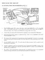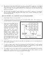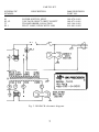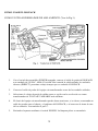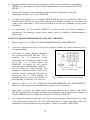
1
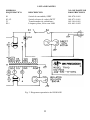
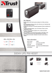
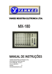
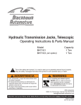
INSTRUCTION
FOLDER
MANUAL DE
INSTRUCCIÓNES
MODEL TR-110
MODELO TR-110
ISOPACK
Direct/ Isolation Transformer
Applications
An isolation transformer is essential for servicing any “hot chassis” (transformerless) AC powered
equipment. Without an isolation transformer, a dangerous electrical shock hazard exists between
the chassis of such equipment and earth ground. There is also a high probability of damage to any
AC powered test equipment used to service such equipment. The B&K Precision Model TR-110
ISOPACK Direct/Isolation Transformer provides the necessary safety factor, allowing the chassis to
be grounded. The ISOPACK also operates as a variable voltage source, providing AC output in
nine steps from 90 to 140 volts. This feature is useful for testing both “hot chassis” and
transformer-powered equipment. Variable voltage testing is valuable for uncovering a voltage
sensitive condition is “problem” radio receivers, television sets, audio equipment, etc. Dual outlets
for the isolated output, and dual outlets for the direct (non-isolated) output provide a convenient
center for connecting both the equipment to be serviced and the associated test equipment. An onoff switch with pilot lamp is provided for the isolated output, which has a power rating of 350 VA
continuous.
HOW TO USE THE “ISOPACK”
AS AN ISOLATION TRANSFORMER (see Fig. 1)
1.
With POWER switch OFF, connect the power cord of the ISOPACK to a 120 volt, 60Hz
outlet. The POWER switch gives on off control to the ISOLATED outlets only; the DIRECT
outlets are always “hot” whenever the ISOPACK is plugged into a live outlet.
2.
Connect the power plug of the transformerless equipment to one of the ISOLATED outlets.
3.
Select the desired output voltage as explained in Step 3 of the “AS A VARIABLE VOLTAGE
TRANSFORMER” section.
4.
The chassis of the transformerless equipment may now be grounded, if desired, by connecting
a test lead between the chassis and the case of the ISOPACK or the ground pin of one of the
outlets
5.
Set the POWER switch to ON. The pilot lamp will light and power will be applied to the
transformerless equipment.
6.
Auxiliary equipment, such as test instruments, may be connected to the DIRECT outlets. Line
voltage, which is unaffected by either the VOLTAGE SELECT switches or the POWER ON
OFF switch, is available here.
7.
The chassis of the transformerless equipment may be grounded or tied to a test equipment
common, through connection to the test equipment instead of the ISOPACK.
2
8.
The total load on the ISOLATED outlets should not exceed 350VA continuous. A load up to
500VA may be powered for 5 minutes maximum if followed by an off period of 5 minutes or
longer for cooling. Avoid using the ISOPACK in a confined area, since this could allow heat
build up to accumulate.
9.
The total load of the DIRECT outlets should not exceed 500VA, continuous or intermittent.
However, both the DIRECT and ISOLATED outputs can be operated simultaneously at up to
full rated load capacity.
HOW TO USE THE “AS A VARIABLE VOLTAGE TRANSFORMER”
1.
Repeat Step 1 of the previous procedure.
2.
Connect the equipment to be powered to one of the ISOLATED outlets. The equipment may
be transformerless or transformer powered.
3.
Select the desired voltage with the
VOLTAGE SELECT switches.
The two 3 position switches are
connected in a matrix arrangement
as shown on the front panel of the
ISOPACK, and in Fig. 2. The
matrix provides nine possible
combinations, each producing a
different output voltage.
For
example, if both switches are in
the center position, a 115 volt
output results. With the “ROW”
switch selecting the top row and
the “COLUMN” switch selecting
the left column, a 110 volt output
results, etc.
4.
Repeat Steps 4 thru 9 of the previous procedure (for tranformer powered equipment, Steps 4
thru 7 are not applicable).
5.
To vary the output voltage, change the combination of VOLTAGE SELECT switch positions
to obtain each desired value. For maximum switch life, it is good practice to turn OFF the
POWER switch before changing the VOLTAGE SELECT switches.
6.
The voltages shown on the matrix (Fig. 2) are approximate, depending upon the load and the
input voltage’s variance from 120 volts. To determine the specific voltage, connect a precision
Multimeter to measure the AC voltage at the ISOLATED output.
3
MAINTENANCE
A 3A fuse protects the unit from excessive overload on the ISOLATED outlets. If the pilot
lamp will not light and there is no output from the ISOLATED outlets, check the fuse. It is
located on the side of the unit adjacent to the power cord. Replace only with a 3A, slow-blow
type 3AG fuse. Correct the overload condition before re-applying power.
The TR-110 fuse does not affect the DIRECT outlets. If there is no output from either the
ISOLATED or DIRECT outlets, check the fuse or circuit breaker panel of your building for the
outlet being used to power the ISOPACK. Correct any overload condition.
SPECIFICATIONS
Input Voltage
105-130VAC, 60Hz
Output Power Rating
Direct
Isolated
500VA
350VA continuous, 500VA intermittent *
Connections
Direct
Isolated
Duplex outlet (3 conductors)
Duplex outlet (3 conductors)
Output Selection
Direct
Isolated
Convenience duplex outlet provides line voltage for auxiliary
Equipment up to 500VA
Two 3 position slide switches provide 9 combinations of
Voltage selection from 90 to 140 volts **, up to 350VA
continuous or 500VA intermittent *. Self-contained power
switch with pilot lamp.
Regulation
No load to full load (350VA), voltage change is less than 4%.
Isolation
Typical leakage current, primary to secondary, 0.1mA.
Size (W x H x D)
5.5” x 5.125” x 8” (13.97 x 13 x 20.3cm)
Weight
11 lbs. (4.99Kg.)
* Intermittent usage: 5 minutes ON followed by 5 minutes or longer OFF.
** Output voltage rated with input at 120 volts.
NOTE: Specifications and information are subject to change without notice. Please visit
www.bkprecision.com for the most current product information.
4
PARTS LIST
SCHEMATIC
SYMBOL
S1
S2, S3
T1
PL 1
DESCRIPTION
B&K PRECISION
PART NO.
POWER SWITCH, SPDT
VOLTAGE SELECT SWITCH, DPTT
TRANSFORMER, ISOLATION
PILOT LAMP, NEON WITH 100K
Fig. 3. ISOPACK schematic diagram.
5
084-070-9-001
084-071-9-001
065-146-9-001
401-001-9-002
Limited One-Year Warranty
B&K Precision Corp. warrants to the original purchaser that its products and the component parts thereof, will
be free from defects in workmanship and materials for a period of one year from date of purchase.
B&K Precision Corp. will, without charge, repair or replace, at its option, defective product or component parts.
Returned product must be accompanied by proof of the purchase date in the form of a sales receipt.
To obtain warranty coverage in the U.S.A., this product must be registered by completing a warranty registration
form on www.bkprecision.com within fifteen (15) days of purchase.
Exclusions: This warranty does not apply in the event of misuse or abuse of the product or as a result of
unauthorized alterations or repairs. The warranty is void if the serial number is altered, defaced or
removed.
B&K Precision Corp. shall not be liable for any consequential damages, including without limitation damages
resulting from loss of use. Some states do not allow limitations of incidental or consequential damages. So the
above limitation or exclusion may not apply to you.
This warranty gives you specific rights and you may have other rights, which vary from state-to-state.
B&K Precision Corp.
22820 Savi Ranch Parkway
Yorba Linda, CA 92887
www.bkprecision.com
714-921-9095
Service Information
Warranty Service: Please return the product in the original packaging with proof of purchase to the address
below. Clearly state in writing the performance problem and return any leads, probes, connectors and accessories
that you are using with the device.
Non-Warranty Service: Return the product in the original packaging to the address below. Clearly state in
writing the performance problem and return any leads, probes, connectors and accessories that you are using
with the device. Customers not on open account must include payment in the form of a money order or credit
card. For the most current repair charges please visit www.bkprecision.com and click on “service/repair”.
Return all merchandise to B&K Precision Corp. with pre-paid shipping. The flat-rate repair charge for NonWarranty Service does not include return shipping. Return shipping to locations in North American is included
for Warranty Service. For overnight shipments and non-North American shipping fees please contact B&K
Precision Corp.
B&K Precision Corp.
22820 Savi Ranch Parkway
Yorba Linda, CA 92887
www.bkprecision.com
714-921-9095
Include with the returned instrument your complete return shipping address, contact name, phone
number and description of problem.
6
MANUAL DE
INSTRUCCIÓNES
MODELO TR-110
ISOPACK
Transformador de aislamiento/directo
APLICACIONES
Un transformador de aislamiento es esencial para dar servicio a cualquier equipo de
“chasis caliente” con suministro de AC (sin transformador). Sin el transformador de
aislamiento existe un serio peligro de choque eléctrico entre el chasis del equipo y tierra
física. Existe también una probabilidad alta de daño a cualquier instrumento AC utilizado
para probar el equipo. El transformador BK Precision modelo TR-110 ISOPACK sirve
justamente para proveer el factor de seguridad, permitiendo el aterrizaje del chasis. El
ISOPACK opera también como una fuente de voltaje variable de AC de 90 a 140 volts en
nueve pasos. Esta característica es de utilidad para probar equipos tanto de chasis caliente
como con transformador; pruebas con voltaje variable son valiosas para detectar
condiciones sensibles al voltaje en radiorreceptores, televisores, equipos de audio, etc. Se
proveen dos enchufes para la salida aislada y dos enchufes para la salida directa (no
aislada), para conectar tanto el equipo bajo prueba como el instrumental de servicio. Se
incluye un interruptor de enc4ndido y lámpara piloto para la salida aislada, con una
potencia de 350VA continua y hasta 500VA en modo intermitente, más que adecuada
para la mayoría de los casos.
7
COMO USAR EL ISOPACK
COMO UN TRANSFORMADOR DE AISLAMIENTO (Vea la Fig.1)
1.
Con el switch de encendido (POWER) apagado, conecte el cable de poder del ISOPACK
a un enchufe de 120VAC, 60Hz. El switch sólo controla la salida aislada; los enchufes
directos (DIRECT) presentan voltaje siempre que se enchufa el ISOPACK.
2.
Conecte el cable de poder del equipo sin transformador a uno de los enchufes aislados.
3.
Seleccione el voltaje deseado de salida como se explica en la sección de uso como
transformador de VOLTAJE VARIABLE más adelante.
4.
El chasis del equipo sin transformador puede ahora aterrizarse, si se desea, conectando un
cable de prueba entre el chasis y el gabinete del ISOPACK, o al conector de tierra de uno
de los enchufes. Vea también el paso 7.
5.
Encienda el aparato mediante el switch POWER. La lámpara piloto se encenderá.
8
6.
Equipos auxiliares (instrumentos de prueba), pueden ahora conectarse a los enchufes
DIRECT, que presentan el voltaje de línea independiente de los switches VOLTAGE
SELECT.
7.
El chasis del equipo sin transformador puede aterrizarse también al común del
instrumento de prueba en vez del ISOPACK.
8.
La carga total continua de los enchufes ISOLATED no debe de exceder de 350VA. Se
permiten hasta 500VA por un período máximo de 5 minutos seguidos de 5 minutos sin
voltaje para enfriamiento. Evite usar el ISOPACK en un área confinada, ya que puede
calentarse.
9.
La carga total de los enchufes DIRECT no debe exceder de 500VA, continua o
intermitente. Sin embargo, puede operar ambos tipos de enchufes simultáneamente a
plena carga.
COMO UN TRANSFORMADOR DE VOLTAJE VARIABLE
1.
Repita el paso 1 de “COMO UN TRANSFORMADOR DE AISLAMIENTO”
2.
Conecte el equipo por activar a uno de los enchufes aislados. El equipo puede ser con o
sin transformador.
3.
Seleccione el voltaje deseado mediante
los switchesVOLTAGE SELECT. Los 2
switches de 3 posiciones Están
conectados en un arreglo de matriz como
en la Fig. 2 y el panel frontal del
ISOPACK. La matriz de 3x3 provee
nueve posibles combinaciones, cada una
con un voltaje de salida distinto. Por
ejemplos, si ambos switches están en la
posición central se obtienen 115 Volts. Al
seleccionar con el switch “ROW” la
columna superior y con el “COLUMN” la
fila izquierda, se obtienen 110 Volts, etc.
Fig. 2. Matriz de selección de voltaje
4.
Repita los pasos 4 a 9 de “COMO UN TRANSFORMADOR DE AISLAMIENTO”
anteriores (para equipos con transformador los pasos 4 a 7 no aplican)
5.
Para variar el voltaje de salida cambie las combinaciones de la matriz VOLTAGE
SELECT para Obtener el voltaje deseado. Para la máxima vida de los switches, apague el
switch POWER antes de cambiar los switches de VOLTAGE SELECT.
6.
Los voltajes de la matriz mostrados en la Fig. 2 son aproximados, dependiendo de la carga
y de la diferencia posible con 120 Volts. Para determinar el voltaje específico, utilice un
multímetro de precisión Precision para medir el voltaje en la salida ISOLATED.
9
MANTENIMIENTO
Un fusible de 3ª protege la unidad de sobrecarga en los enchufes ISOLATED. Si la lámpara
piloto no enciende y no hay voltaje en dichos enchufes, verifique el fusible. Se localiza a un
lado de la unidad adyacente al cable de poder. Reemplácelo por un fusible de lenta fusión de 3ª
tipo 3AG. Corrija la condición de sobrecarga antes de reencender la unidad.
El fusible no afecta los enchufes DIRECT. Si no hay voltaje en ninguna de los enchufes
(ISOLATED Y DIRECT), verifique el fusible o el panel de interruptores de su edificio
(breakers). Corrija cualquier condición de sobrecarga.
ESPECIFICACIONES
Requerimientos de entrada
105-130VAC, 60Hz
Potencia de salida
Direct
Isolated
500VA
350VA contínua, 500VA intermitente*
Conexiones
Direct
Isolated
Enchufe dúplex (3 conductores)
Enchufe dúplex (3 conductores)
Selección de salida
Direct
Isolated
Regulación
El enchufe dúplex provee voltaje de línea para
equipo auxiliar hasta 500VA
Dos switches deslizables proveen 9 combinaciones
de voltaje de 90 a 140 volts**, hasta 350VA
continuos o 500VA intermitentes. Switch interno
con lámpara piloto.
No hay sin carga o a plena carga (350VA). El
cambio de voltaje es menor a 4%
Aislamiento
Corriente de fuga típica de 0.1mA, primario a
secundario
Tamaño
5 ½ x 5 1/8 x 8”
Peso
11 libras
*Uso intermitente: 5 minutos encendido seguido de 5 minutos o más apagado
** Voltajes de salida determinados con entrada de 120 volts
NOTA: Las especificaciones y la información están conforme a cambio sin el aviso de B&K
Precision Corp. Por favor visite www.bkprecision.com para las especificaciones más corriente y
información de nuestros productos.
10
LISTA DE PARTES
SIMBOLO
ESQUEMATICO
DESCRIPCION
NO. DE PARTE DE
B&K PRECISION
S1
S2, S3
T1
PL1
Switch de encendido, SPDT
Switch selector de voltaje,DPTT
Transformador de aislamiento
Lámpara piloto, Neón con 100K
084-070-9-001
084-071-9-001
065-146-9-001
401-001-9-002
INFORMACION SOBRE PEDIDO DE PARTES
Fig. 3. Diagrama esquemático del ISOPACK
11
Garantía Limitada de Un Ano
B&K Precision Corp. Autorizaciones al comprador original que su productos y componentes serán libre de
defectos por el periodo de un ano desde el día en que se compro.
B&K Precision Corp. sin carga, repararemos o sustituir, a nuestra opción, producto defectivo o componentes.
Producto devuelto tiene que ser acompañado con prueba de la fecha del la compra en la forma de un recibo de
las ventas.
Para obtener cobertura en los EE.UU., este producto debe ser registrado por medio de la forma de registro en
www.bkprecision.com dentro de quince (15) días de la compra de este producto.
Exclusiones: Esta garantía no se aplica en el evento de uso en error o abuso de este producto o el resultado
de alteraciones desautorizado o reparaciones. La garantía es vacía si se altera, se desfigura o se quita el
número de serie.
B&K Precision Corp. no será obligado a dar servicio por danos consecuente, incluyendo sin limitaciones a danos
resultando en perdida de uso. Algunos estados no permiten limitaciones de daños fortuitos o consecuentes. Tan
la limitación o la exclusión antedicha puede no aplicarse a usted.
Esta garantía le da ciertos derechos y pueden tener otros derechos, cuales cambian estado por estado.
B&K Precision Corp.
22820 Savi Ranch Parkway
Yorba Linda, CA 92887
www.bkprecision.com
714-921-9095
Información de Servicio
Servicio de Garantía: Por favor regrese el producto en el empaquetado original con prueba de la fecha de la
compra a la dirección debajo. Indique claramente el problema en escritura, incluya todos los accesorios que se
estan usado con el equipo.
Servicio de No Garantía: Por favor regrese el producto en el empaquetado original con prueba de la fecha de la
compra a la dirección debajo. Indique claramente el problema en escritura, incluya todos los accesorios que se
estan usado con el equipo. Clientes que no tienen cuentas deben de incluir pago en forma de queque, orden de
dinero, o numero de carta de crédito. Para los precisos mas corriente visite www.bkprecision.com y oprime
“service/repair”.
Vuelva toda la mercancía a B&K Precision Corp. con el envío pagado por adelantado. La carga global de la
reparación para el servicio de la No-Garantía no incluye el envío de vuelta. El envío de vuelta a las
localizaciones en norte americano es incluido para el servicio de la garantía. Para los envíos de noche y el envío
del no-Norte los honorarios americanos satisfacen el contacto B&K Precision Corp.
B&K Precision Corp.
22820 Savi Ranch Parkway
Yorba Linda, CA 92887
www.bkprecision.com
714-921-9095
Incluya con el instrumento la dirección de vuelto para envío, nombre del contacto, número de teléfono y
descripción del problema.
12
Declaration of CE Conformity
according to EEC directives and NF EN 45014 norm
Responsible Party
Alternate Manufacturing Site
Manufacturer’s Name:
B&K Precision Corporation
B&K India 0650
Manufacture’s Address:
22820 Savi Ranch Pkwy.
Yorba Linda, CA 92887-4610
USA
Declares that the below mentioned product
Product Name:
Isolation Transformer
Part Numbers:
TR 110
complies with the essential requirements of the following applicable European Directives:
Low Voltage Directive 73/23/EEC (19.02.73) amended by
93/68/EEC (22.07.93)
Electromagnetic Compatibility (EMC) 89/336/EEC (03.05.88)
amended by 92/68/EEC (22.07.93)
and conforms with the following product standards:
LVD
EN 61010-1:1990 + amend 1:1992 + amend 2:1995
EMC
EN 50082-1 (Immunity):
EN 61000-4-2 (EDS)
EN 61000-4-3 (Radiated Surge)
EN 61000-4-4 (Burst & EFT)
EN 61000-4-11 (Voltage dips)
EN 50081-1 (Emission):
IEC 801-3 (Radiated Susceptibility)
This Declaration of Conformity applies to above listed products place on the EU market after
February 28, 2006
Date
Victor Tolan
President
22820 Savi Ranch Parkway • Yorba Linda, CA 92887
© 2005 B+K Precision
481-108-9-001
Printed in U.S.A.
7