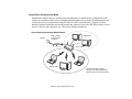
1
User’s Guide
Learn how to use
your Fujitsu LifeBook
P1620 notebook
Copyright and Trademark Information
Fujitsu Computer Systems Corporation has made every effort to ensure the accuracy and completeness of this document; however, as
ongoing development efforts are continually improving the capabilities of our products, we cannot guarantee the accuracy of the contents
of this document. We disclaim liability for errors, omissions, or future changes.
Fujitsu, the Fujitsu logo, and LifeBook are registered trademarks of Fujitsu Limited.
Intel, Intel Core, Centrino, and Intel Centrino Pro are trademarks or registered trademarks of Intel Corporation or its subsidiaries in
the United States and other countries.
Microsoft, Windows, Windows Vista, and OneNote are either registered trademarks or trademarks of Microsoft Corporation in the
United States and/or other countries.
PCMCIA is a trademark of the Personal Computer Memory Card International Association.
EverNote is a registered trademark of EverNote Corporation.
Bluetooth is a trademark of Bluetooth SIG, Inc., USA.
Google and Picasa are trademarks or registered trademarks of Google Incorporated.
OmniPass is a trademark of Softex, Inc.
Adobe, Acrobat, and Acrobat Reader are either a registered trademarks or trademarks of Adobe Systems Incorporated in the United
States and/or other countries.
Norton and Norton Internet Security are trademarks or registered trademarks of Symantec Corporation in the United States and other
countries.
All other trademarks mentioned herein are the property of their respective owners.
WARNING
HANDLING THE CORD ON THIS PRODUCT WILL EXPOSE YOU TO LEAD, A CHEMICAL KNOWN TO THE
STATE OF CALIFORNIA TO CAUSE BIRTH DEFECTS OR OTHER REPRODUCTIVE HARM.
WASH HANDS AFTER HANDLING.
© Copyright 2007 Fujitsu Computer Systems Corporation. All rights reserved.
No part of this publication may be copied, reproduced, or translated, without prior written consent of Fujitsu. No part of this publication
may be stored or transmitted in any electronic form without the written consent of Fujitsu.
B5FJ-6461-01EN-00
DECLARATION OF CONFORMITY
according to FCC Part 15
Responsible Party Name:
Fujitsu Computer Systems Corporation
Address:
1250 E. Arques Avenue, M/S 122
Sunnyvale, CA 94085
Telephone:
(408) 746-6000
Declares that product:
Base Model Configuration:
LifeBook P1620 notebook
Complies with Part 15 of the FCC Rules.
This device complies with Part 15 of the FCC rules. Operations are subject to the following two conditions:
(1) This device may not cause harmful interference, (2) This device must accept any interference received,
including interference that may cause undesired operation.
IMPORTANT SAFETY INSTRUCTIONS
This unit requires an AC adapter to operate. Use only UL Listed I.T.E. Class II Adapters with an output rating of 16 VDC, with a
current of 2.5 A.
+
AC adapter output polarity:
When using your notebook equipment, basic safety precautions should always be followed to reduce the risk of fire, electric shock and
injury to persons, including the following:
•
CAUTION - HOT SURFACE: The bottom of this notebook computer can become hot when used for long periods of time. When
using this notebook, take caution to limit long term or continuous use while resting it on exposed skin, such as the lap.
•
Do not use this product near water for example, near a bathtub, washbowl, kitchen sink or laundry tub, in a wet basement or near a
swimming pool.
•
•
•
Avoid using a modem during an electrical storm. There may be a remote risk of electric shock from lightning.
•
•
To reduce the risk of fire, use only No. 26 AWG or larger UL Listed or CSA Certified Telecommunication Line Cord.
Do not use a modem to report a gas leak in the vicinity of the leak.
Use only the power cord and batteries indicated in this manual. Do not dispose of batteries in a fire. They may explode. Check with
local codes for possible special disposal instructions.
For TV tuner use: To protect from overvoltages and transients on the Cable Distribution System, make sure that the outer shield of
the coaxial cable is connected to earth (grounded) at the building premise as close to the point of cable entrance as practicable, as
required per NEC Article 820.93, ANSI/NFPA 70: 2005. If you have questions about your CATV installation, contact your service
provider.
SAVE THESE INSTRUCTIONS
For Authorized Repair Technicians Only
DANGER OF EXPLOSION IF LITHIUM (CLOCK) BATTERY IS INCORRECTLY REPLACED. REPLACE ONLY
WITH THE SAME OR EQUIVALENT TYPE RECOMMENDED BY THE MANUFACTURER. DISPOSE OF USED
BATTERIES ACCORDING TO THE MANUFACTURER’S INSTRUCTION.
FOR CONTINUED PROTECTION AGAINST RISK OF FIRE, REPLACE ONLY WITH THE SAME TYPE AND
RATING FUSE.
Recycling your battery
Over time, the batteries that run your mobile computer will begin to hold a charge for a shorter amount of time; this is a natural
occurrence for all batteries. When this occurs, you may want to replace the battery with a fresh one*. If you replace it, it is important
that you dispose of the old battery properly because batteries contain materials that could cause environmental damage if disposed of
improperly.
Fujitsu is very concerned with environmental protection, and has enlisted the services of the Rechargeable Battery
Recycling Corporation (RBRC)**, a non-profit public service organization dedicated to protecting our environment
by recycling old batteries at no cost to you.
RBRC has drop-off points at tens of thousands of locations throughout the United States and Canada. To find the
location nearest you, go to www.RBRC.org or call 1-800-822-8837.
If there are no convenient RBRC locations near you, you can also go to the EIA Consumer Education Initiative website
(http://EIAE.org/) and search for a convenient disposal location.
Remember – protecting the environment is a cooperative effort, and you should make every effort to protect it for current and future
generations.
*
To order a new battery for your Fujitsu mobile computer, go to the Fujitsu shopping site at www.shopfujitsu.com in the US or
www.fujitsu.ca/products/notebooks in Canada.
** RBRC is an independent third party to which Fujitsu provides funding for battery recycling; RBRC is in no way affiliated with
Fujitsu.
Contents
Preface
About This Guide . . . . . . . . . . . . . . . . . . . . . . . . . . . . . . . . . . . . . . . . . . . . . 13
Conventions Used in the Guide . . . . . . . . . . . . . . . . . . . . . . . . . . . . . . . . . 13
Fujitsu Contact Information . . . . . . . . . . . . . . . . . . . . . . . . . . . . . . . . . . . . 14
Chapter 1
Getting to Know Your LifeBook
Overview . . . . . . . . . . . . . . . . . . . . . . . . . . . . . . . . . . . . . . . . . . . . . . . . . . . . 16
Locating the Controls and Connectors . . . . . . . . . . . . . . . . . . . . . . . . . . . . 17
Front and Display Components . . . . . . . . . . . . . . . . . . . . . . . . . . . . . . . . .
Left-Side Panel Components . . . . . . . . . . . . . . . . . . . . . . . . . . . . . . . . . . .
Right-Side Panel Components . . . . . . . . . . . . . . . . . . . . . . . . . . . . . . . . . .
Back Panel Components. . . . . . . . . . . . . . . . . . . . . . . . . . . . . . . . . . . . . . .
Bottom Components. . . . . . . . . . . . . . . . . . . . . . . . . . . . . . . . . . . . . . . . . .
20
22
23
25
27
Status Indicator Panel . . . . . . . . . . . . . . . . . . . . . . . . . . . . . . . . . . . . . . . . . 29
Power Indicator . . . . . . . . . . . . . . . . . . . . . . . . . . . . . . . . . . . . . . . . . . . . .
Battery Level Indicator. . . . . . . . . . . . . . . . . . . . . . . . . . . . . . . . . . . . . . . .
Hard Drive Access Indicator . . . . . . . . . . . . . . . . . . . . . . . . . . . . . . . . . . .
NumLk Indicator . . . . . . . . . . . . . . . . . . . . . . . . . . . . . . . . . . . . . . . . . . . .
30
30
31
31
CapsLock Indicator. . . . . . . . . . . . . . . . . . . . . . . . . . . . . . . . . . . . . . . . . . . 31
ScrLk Indicator . . . . . . . . . . . . . . . . . . . . . . . . . . . . . . . . . . . . . . . . . . . . . . 31
Display Panel . . . . . . . . . . . . . . . . . . . . . . . . . . . . . . . . . . . . . . . . . . . . . . . . . 32
Opening the Display Panel . . . . . . . . . . . . . . . . . . . . . . . . . . . . . . . . . . . . . 32
Using the System as a Tablet . . . . . . . . . . . . . . . . . . . . . . . . . . . . . . . . . . . 33
Display Orientations in Tablet Configuration . . . . . . . . . . . . . . . . . . . . . . 34
Adjusting Display Panel Brightness . . . . . . . . . . . . . . . . . . . . . . . . . . . . . . 35
Keyboard . . . . . . . . . . . . . . . . . . . . . . . . . . . . . . . . . . . . . . . . . . . . . . . . . . . . 37
Using the Keyboard . . . . . . . . . . . . . . . . . . . . . . . . . . . . . . . . . . . . . . . . . . 37
Quick Point Pointing Device/Touch Screen . . . . . . . . . . . . . . . . . . . . . . . . 40
Quick Point Control Adjustment . . . . . . . . . . . . . . . . . . . . . . . . . . . . . . . . 42
Clicking. . . . . . . . . . . . . . . . . . . . . . . . . . . . . . . . . . . . . . . . . . . . . . . . . . . . 44
Calibrating the Touch Screen . . . . . . . . . . . . . . . . . . . . . . . . . . . . . . . . . . . 45
Double-Clicking . . . . . . . . . . . . . . . . . . . . . . . . . . . . . . . . . . . . . . . . . . . . . 45
Dragging . . . . . . . . . . . . . . . . . . . . . . . . . . . . . . . . . . . . . . . . . . . . . . . . . . . 45
Volume Control . . . . . . . . . . . . . . . . . . . . . . . . . . . . . . . . . . . . . . . . . . . . . . . 47
Controlling the Volume . . . . . . . . . . . . . . . . . . . . . . . . . . . . . . . . . . . . . . . 47
LifeBook Security/Application Panel . . . . . . . . . . . . . . . . . . . . . . . . . . . . . 48
Setting up Your LifeBook Security Panel . . . . . . . . . . . . . . . . . . . . . . . . . 49
Passwords . . . . . . . . . . . . . . . . . . . . . . . . . . . . . . . . . . . . . . . . . . . . . . . . . . 49
Operating Your LifeBook Security/Application Panel. . . . . . . . . . . . . . . . 51
Precautions . . . . . . . . . . . . . . . . . . . . . . . . . . . . . . . . . . . . . . . . . . . . . . . . . 52
Uninstalling the Security Panel Application. . . . . . . . . . . . . . . . . . . . . . . . 53
Launching Applications with the Security/Application Panel . . . . . . . . . . 54
Changing Button Functions . . . . . . . . . . . . . . . . . . . . . . . . . . . . . . . . . . . . 57
7
Chapter 2
Getting Started with Your LifeBook
Power Sources . . . . . . . . . . . . . . . . . . . . . . . . . . . . . . . . . . . . . . . . . . . . . . . . 60
Connecting the Power Adapters . . . . . . . . . . . . . . . . . . . . . . . . . . . . . . . . . 60
Starting Your LifeBook Notebook. . . . . . . . . . . . . . . . . . . . . . . . . . . . . . . . 61
Power On . . . . . . . . . . . . . . . . . . . . . . . . . . . . . . . . . . . . . . . . . . . . . . . . . . 61
Boot Sequence . . . . . . . . . . . . . . . . . . . . . . . . . . . . . . . . . . . . . . . . . . . . . . 62
Hard Disk Drive Passwords . . . . . . . . . . . . . . . . . . . . . . . . . . . . . . . . . . . . 62
BIOS Setup Utility . . . . . . . . . . . . . . . . . . . . . . . . . . . . . . . . . . . . . . . . . . . 63
Booting the System. . . . . . . . . . . . . . . . . . . . . . . . . . . . . . . . . . . . . . . . . . . 64
Starting Windows Vista the first time . . . . . . . . . . . . . . . . . . . . . . . . . . . . 65
Starting Windows XP the First Time . . . . . . . . . . . . . . . . . . . . . . . . . . . . . 66
Registering Your LifeBook notebook with Fujitsu . . . . . . . . . . . . . . . . . . 67
Installing ClickMe!. . . . . . . . . . . . . . . . . . . . . . . . . . . . . . . . . . . . . . . . . . . 67
Fujitsu Driver Update Utility . . . . . . . . . . . . . . . . . . . . . . . . . . . . . . . . . . . 68
Power Management. . . . . . . . . . . . . . . . . . . . . . . . . . . . . . . . . . . . . . . . . . . . 69
Power/Suspend/Resume Button . . . . . . . . . . . . . . . . . . . . . . . . . . . . . . . . . 69
Standby (Sleep) Mode . . . . . . . . . . . . . . . . . . . . . . . . . . . . . . . . . . . . . . . . 70
Hibernation (Save-to-Disk) Feature . . . . . . . . . . . . . . . . . . . . . . . . . . . . . . 71
Windows Power Management . . . . . . . . . . . . . . . . . . . . . . . . . . . . . . . . . . 71
Restarting the System . . . . . . . . . . . . . . . . . . . . . . . . . . . . . . . . . . . . . . . . . 72
Powering Off . . . . . . . . . . . . . . . . . . . . . . . . . . . . . . . . . . . . . . . . . . . . . . . 72
Chapter 3
User-Installable Features
Lithium ion Battery. . . . . . . . . . . . . . . . . . . . . . . . . . . . . . . . . . . . . . . . . . . . 74
Recharging the Batteries. . . . . . . . . . . . . . . . . . . . . . . . . . . . . . . . . . . . . . . 75
Replacing the Battery . . . . . . . . . . . . . . . . . . . . . . . . . . . . . . . . . . . . . . . . . 76
8
Memory Upgrade Module . . . . . . . . . . . . . . . . . . . . . . . . . . . . . . . . . . . . . . 79
Removing Memory Modules . . . . . . . . . . . . . . . . . . . . . . . . . . . . . . . . . . . 79
Installing a Memory Upgrade Module . . . . . . . . . . . . . . . . . . . . . . . . . . . . 81
Checking the Memory Capacity . . . . . . . . . . . . . . . . . . . . . . . . . . . . . . . . . 81
Secure Digital Cards . . . . . . . . . . . . . . . . . . . . . . . . . . . . . . . . . . . . . . . . . . . 83
Inserting SD Cards . . . . . . . . . . . . . . . . . . . . . . . . . . . . . . . . . . . . . . . . . . . 84
Removing An SD Card . . . . . . . . . . . . . . . . . . . . . . . . . . . . . . . . . . . . . . . . 84
PC Cards . . . . . . . . . . . . . . . . . . . . . . . . . . . . . . . . . . . . . . . . . . . . . . . . . . . . 85
Installing PC Cards . . . . . . . . . . . . . . . . . . . . . . . . . . . . . . . . . . . . . . . . . . . 86
Removing PC Cards . . . . . . . . . . . . . . . . . . . . . . . . . . . . . . . . . . . . . . . . . . 86
Smart Card Reader . . . . . . . . . . . . . . . . . . . . . . . . . . . . . . . . . . . . . . . . . . . 87
Port Replicator . . . . . . . . . . . . . . . . . . . . . . . . . . . . . . . . . . . . . . . . . . . . . . . 88
Port Replicator Components. . . . . . . . . . . . . . . . . . . . . . . . . . . . . . . . . . . . 88
Attaching Port Replicator . . . . . . . . . . . . . . . . . . . . . . . . . . . . . . . . . . . . . . 90
Detaching Port Replicator. . . . . . . . . . . . . . . . . . . . . . . . . . . . . . . . . . . . . . 90
Device Ports . . . . . . . . . . . . . . . . . . . . . . . . . . . . . . . . . . . . . . . . . . . . . . . . . . 91
Modem (RJ-11) Jack. . . . . . . . . . . . . . . . . . . . . . . . . . . . . . . . . . . . . . . . . . 91
Internal LAN (RJ-45) jack . . . . . . . . . . . . . . . . . . . . . . . . . . . . . . . . . . . . . 92
Docking Port. . . . . . . . . . . . . . . . . . . . . . . . . . . . . . . . . . . . . . . . . . . . . . . . 92
Universal Serial Bus Ports . . . . . . . . . . . . . . . . . . . . . . . . . . . . . . . . . . . . . 92
Microphone Jack. . . . . . . . . . . . . . . . . . . . . . . . . . . . . . . . . . . . . . . . . . . . . 93
Headphone Jack . . . . . . . . . . . . . . . . . . . . . . . . . . . . . . . . . . . . . . . . . . . . . 93
External Video Port . . . . . . . . . . . . . . . . . . . . . . . . . . . . . . . . . . . . . . . . . . 93
9
Chapter 4
Troubleshooting Your LifeBook
Troubleshooting. . . . . . . . . . . . . . . . . . . . . . . . . . . . . . . . . . . . . . . . . . . . . . . 95
Identifying the Problem . . . . . . . . . . . . . . . . . . . . . . . . . . . . . . . . . . . . . . . 95
Specific Problems . . . . . . . . . . . . . . . . . . . . . . . . . . . . . . . . . . . . . . . . . . . . 97
Power On Self Test Messages . . . . . . . . . . . . . . . . . . . . . . . . . . . . . . . . . . 107
Restoring Your Pre-installed Software . . . . . . . . . . . . . . . . . . . . . . . . . . . . 112
Re-installing Individual Drivers and Applications . . . . . . . . . . . . . . . . . . . 112
Restoring the Operating System for Windows XP Systems. . . . . . . . . . . . 113
Restoring the Operating System for Windows Vista Systems . . . . . . . . . . 114
Automatically Downloading Driver Updates . . . . . . . . . . . . . . . . . . . . . . . 118
Chapter 5
Care and Maintenance
Caring for your LifeBook Notebook . . . . . . . . . . . . . . . . . . . . . . . . . . . . . . 119
Cleaning your LifeBook notebook . . . . . . . . . . . . . . . . . . . . . . . . . . . . . . . 121
Storing your LifeBook notebook . . . . . . . . . . . . . . . . . . . . . . . . . . . . . . . . 122
Traveling with your LifeBook notebook . . . . . . . . . . . . . . . . . . . . . . . . . . 123
Batteries . . . . . . . . . . . . . . . . . . . . . . . . . . . . . . . . . . . . . . . . . . . . . . . . . . . 124
Media Care . . . . . . . . . . . . . . . . . . . . . . . . . . . . . . . . . . . . . . . . . . . . . . . . . 125
Chapter 6
System Specifications
Specifications . . . . . . . . . . . . . . . . . . . . . . . . . . . . . . . . . . . . . . . . . . . . . . . . . 126
Configuration Label . . . . . . . . . . . . . . . . . . . . . . . . . . . . . . . . . . . . . . . . . . 126
Microprocessor . . . . . . . . . . . . . . . . . . . . . . . . . . . . . . . . . . . . . . . . . . . . . . 127
Chipset . . . . . . . . . . . . . . . . . . . . . . . . . . . . . . . . . . . . . . . . . . . . . . . . . . . . 127
Memory. . . . . . . . . . . . . . . . . . . . . . . . . . . . . . . . . . . . . . . . . . . . . . . . . . . . 127
Video. . . . . . . . . . . . . . . . . . . . . . . . . . . . . . . . . . . . . . . . . . . . . . . . . . . . . . 127
Audio . . . . . . . . . . . . . . . . . . . . . . . . . . . . . . . . . . . . . . . . . . . . . . . . . . . . . 128
Mass Storage Device Options. . . . . . . . . . . . . . . . . . . . . . . . . . . . . . . . . . . 128
Features. . . . . . . . . . . . . . . . . . . . . . . . . . . . . . . . . . . . . . . . . . . . . . . . . . . . 128
10
Device Ports . . . . . . . . . . . . . . . . . . . . . . . . . . . . . . . . . . . . . . . . . . . . . . . . 129
Keyboard. . . . . . . . . . . . . . . . . . . . . . . . . . . . . . . . . . . . . . . . . . . . . . . . . . . 130
Power . . . . . . . . . . . . . . . . . . . . . . . . . . . . . . . . . . . . . . . . . . . . . . . . . . . . . 130
Dimensions and Weight . . . . . . . . . . . . . . . . . . . . . . . . . . . . . . . . . . . . . . . 131
Environmental Requirements . . . . . . . . . . . . . . . . . . . . . . . . . . . . . . . . . . . 131
Popular Accessories . . . . . . . . . . . . . . . . . . . . . . . . . . . . . . . . . . . . . . . . . . 131
Pre-Installed Software . . . . . . . . . . . . . . . . . . . . . . . . . . . . . . . . . . . . . . . . 132
Learning About Your Software . . . . . . . . . . . . . . . . . . . . . . . . . . . . . . . . . 132
Glossary/Regulatory
Glossary . . . . . . . . . . . . . . . . . . . . . . . . . . . . . . . . . . . . . . . . . . . . . . . . . . . . . 135
Regulatory Information . . . . . . . . . . . . . . . . . . . . . . . . . . . . . . . . . . . . . . . . 151
Appendix A: WLAN User’s Guide
Before Using the Optional Wireless LAN . . . . . . . . . . . . . . . . . . . . . . . . . . 159
Wireless LAN Device Covered by this Document. . . . . . . . . . . . . . . . . . . 159
Characteristics of the WLAN Device . . . . . . . . . . . . . . . . . . . . . . . . . . . . . 159
Wireless LAN Modes Using this Device . . . . . . . . . . . . . . . . . . . . . . . . . . 160
Wireless Network Considerations . . . . . . . . . . . . . . . . . . . . . . . . . . . . . . . 162
Deactivating the WLAN Device. . . . . . . . . . . . . . . . . . . . . . . . . . . . . . . . . 162
Activating the WLAN Device . . . . . . . . . . . . . . . . . . . . . . . . . . . . . . . . . . 164
Configuring the Wireless LAN. . . . . . . . . . . . . . . . . . . . . . . . . . . . . . . . . . . 165
Configuring the WLAN Using Windows Vista . . . . . . . . . . . . . . . . . . . . . 165
Configuring the WLAN Using Windows XP . . . . . . . . . . . . . . . . . . . . . . 166
Connection to the network . . . . . . . . . . . . . . . . . . . . . . . . . . . . . . . . . . . . . 166
Troubleshooting the WLAN. . . . . . . . . . . . . . . . . . . . . . . . . . . . . . . . . . . . . 167
Troubleshooting . . . . . . . . . . . . . . . . . . . . . . . . . . . . . . . . . . . . . . . . . . . . . 167
11
WLAN Specifications . . . . . . . . . . . . . . . . . . . . . . . . . . . . . . . . . . . . . . . . . . 169
Specifications . . . . . . . . . . . . . . . . . . . . . . . . . . . . . . . . . . . . . . . . . . . . . . . 169
Using the Bluetooth Device. . . . . . . . . . . . . . . . . . . . . . . . . . . . . . . . . . . . . . 171
What is Bluetooth . . . . . . . . . . . . . . . . . . . . . . . . . . . . . . . . . . . . . . . . . . . . 171
Where to Find Information About Bluetooth . . . . . . . . . . . . . . . . . . . . . . . 171
Appendix B: Fingerprint Sensor Device
Introducing the Fingerprint Sensor Device . . . . . . . . . . . . . . . . . . . . . . . . 173
Getting Started . . . . . . . . . . . . . . . . . . . . . . . . . . . . . . . . . . . . . . . . . . . . . . 174
Installing OmniPass . . . . . . . . . . . . . . . . . . . . . . . . . . . . . . . . . . . . . . . . . . 174
User Enrollment . . . . . . . . . . . . . . . . . . . . . . . . . . . . . . . . . . . . . . . . . . . . . 177
Using OmniPass . . . . . . . . . . . . . . . . . . . . . . . . . . . . . . . . . . . . . . . . . . . . . 180
Configuring OmniPass . . . . . . . . . . . . . . . . . . . . . . . . . . . . . . . . . . . . . . . . 186
OmniPass Control Center . . . . . . . . . . . . . . . . . . . . . . . . . . . . . . . . . . . . . . 188
Troubleshooting . . . . . . . . . . . . . . . . . . . . . . . . . . . . . . . . . . . . . . . . . . . . . 190
Index
Index . . . . . . . . . . . . . . . . . . . . . . . . . . . . . . . . . . . . . . . . . . . . . . . . . . . . . . . . 192
12
Preface
About This Guide
The LifeBook® P1600 Series notebook from Fujitsu Computer Systems Corporation is a small yet
powerful convertible computer. It can be used either as a standard notebook using keyboard or pen
input, or as a tablet using pen input. It is powered by an Intel® Core2™ Duo processor and an
integrated Intel 945GMS graphics controller with support for up to 224 MB of shared graphics
memory. The notebook has a built-in 8.9” TFT wide XGA color display.
This manual explains how to operate your LifeBook P1600 Series notebook’s hardware and built-in
system software. Your LifeBook P1620 notebook comes with Windows® XP Tablet PC Edition 2005,
Windows XP Professional Edition, or Windows Vista™ Business pre-installed.
Conventions Used in the Guide
Keyboard and on-screen keys appear in brackets. Example: [Fn], [F1], [ESC], [ENTER] and [CTRL].
Pages with additional information about a specific topic are cross-referenced within the text.
For example: (“See Installation Procedure on page 43”.) Note that all cross-references are linked to the
referenced items, so by clicking the link, you will automatically go to the referenced item or page.
On-screen menu items appear in bold. Example: “Click Fujitsu Menu, and select your choice”.
13
THE INFORMATION ICON HIGHLIGHTS INFORMATION THAT WILL ENHANCE YOUR UNDERSTANDING OF
THE SUBJECT MATERIAL.
THE CAUTION ICON HIGHLIGHTS INFORMATION THAT IS IMPORTANT TO THE SAFE OPERATION OF YOUR
PLEASE READ ALL CAUTION INFORMATION
CAREFULLY.
COMPUTER, OR TO THE INTEGRITY OF YOUR FILES.
THE WARNING ICON HIGHLIGHTS INFORMATION THAT CAN BE HAZARDOUS TO EITHER YOU, YOUR
LIFEBOOK NOTEBOOK, OR YOUR FILES. PLEASE READ ALL WARNING INFORMATION CAREFULLY.
Fujitsu Contact Information
Service and Support
You can contact Fujitsu Service and Support in the following ways:
• Toll free: 1-800-8Fujitsu (1-800-838-5487)
• E-mail: [email protected]
• Website: http://www.computers.us.fujitsu.com/support
Before you place the call, you should have the following information ready so that the customer
support representative can provide you with the fastest possible solution:
• Product name
• Product configuration number
• Product serial number
14 - About This Guide
•
•
•
•
Purchase date
Conditions under which the problem occurred
Any error messages that have occurred
Type of device connected, if any
Fujitsu Shopping Online
You can go directly to the online by going to the website at: www.shopfujitsu.com.
YOU MUST HAVE AN ACTIVE INTERNET CONNECTION TO USE THE ONLINE URL LINKS.
Limited Warranty
Your LifeBook P1620 notebook is backed by a Fujitsu International Limited Warranty. Check the
service kit that came with your notebook for the Limited Warranty period and terms and conditions.
15 - About This Guide
Chapter 1
Getting to Know Your LifeBook
Overview
This section describes the
components of your Fujitsu
LifeBook P1620 notebook. We
strongly recommend that you read
it before using your notebook –
even if you are already familiar
with notebook computers.
Figure 1. Fujitsu LifeBook P1620 notebook
16
Locating the Controls and Connectors
Connectors and peripheral interfaces on the LifeBook P1620 notebook and the optional port replicator
allow you to connect a variety of devices. Specific locations are illustrated in Figures 2 through 6. The
table below provides a short description of each icon on the LifeBook P1620 notebook and/or optional
port replicator. Each of the icons is either molded into or printed on the notebook or port replicator chassis.
Connection
Notebook
Icon
Purpose
DC in connector
Connect an external power source such as the AC adapter or auto/airline
adapter.
Secure Digital
(SD) Slot
The Secure Digital (SD) card slot allows you to install a flash memory card
for data storage. Flash memory cards allow you to transfer data to and from
a variety of different digital devices.
USB Ports
Connect Universal Serial Bus 2.0 or 1.1 compliant devices to the
notebook.
PCMCIA
Card slot
Insert Type I or Type II PC Cards.
Fingerprint Sensor
Use the fingerprint sensor to log onto the system using your fingerprint as
the “password”.
Microphone Jack
Connect an external microphone. The internal microphone is disabled
when you plug in an external microphone. The same icon is used for the
internal microphone.
17 - Locating the Controls and Connectors
Connection
Notebook
Icon
Purpose
Headphone Jack
Connect stereo headphones or powered external speakers. The internal
speaker is disabled when you plug in external headphones or powered
speakers.
Modem
Connect a telephone line to the internal modem using a standard RJ-11
telephone plug.
Security lock slot
The security slot allows you to secure the notebook using compatible
locking devices.
Suspend/ Resume
button
The Suspend/Resume button allows you to suspend notebook activity
without powering off, resume your notebook from suspend mode, and
power on the system when it has been shut down from Windows.
Local Area
Network (LAN)
The LAN (RJ-45) jack is used to connect the internal 10/100 Base-T/Tx
Ethernet to a Local Area Network (LAN) in your office or home, or
broadband devices such as a cable modem, DSL, or satellite Internet.
Battery Release
Latch
The battery release latch allows you to remove the battery from your
system for storage or replacement.
Wireless LAN/
Bluetooth On/Off
Switch
The wireless LAN switch allows you to turn power to the optional wireless
LAN device on and off.
18 - Locating the Controls and Connectors
Display Panel Latch
Built-in Microphone
Fingerprint Sensor
Display Panel
LifeBook Security/
Application Panel Buttons
Speaker
Power/Suspend/
Resume Button
Quick Point
Pointing Device
Status Indicator Panel
Keyboard
Figure 2. LifeBook notebook with display open
19 - Locating the Controls and Connectors
Front and Display Components
The following is a brief description of your LifeBook notebook’s front and display features.
Display Panel Latch
The display panel latch holds the display panel in position.
Display Panel
The display panel is a color LCD panel with back lighting for the display of text and graphics and touch
screen functionality.
Suspend/Resume Button
The Suspend/Resume button allows you to suspend system activity without powering off, resume your
system from standby mode, and power on your system when it has been shut down from the Windows
operating system. See “Power On” on page 61.
Status Indicator Panel
The Status Indicator Panel displays symbols that correspond to specific components of your LifeBook
P1600 Series notebook. See “Status Indicator Panel” on page 29.
Keyboard
A full-function keyboard with dedicated Windows keys. See “Keyboard” on page 37.
Quick Point Pointing Device
The Quick Point pointing device consists of two mouse-like buttons, one scroll button, and a cursor
control button (located near the center of the keyboard). See “” on page 46.
Speaker
The speaker allows you to listen to sound from your system.
20 - Locating the Controls and Connectors
LifeBook Security/Application Buttons
The LifeBook P1600 Series notebook Security/Application Buttons provide application launch
capabilities. See “LifeBook Security/Application Panel” on page 48.
Fingerprint Sensor
The fingerprint recognition sensor allows you to log into Windows or other applications by replacing your
username and password. See “Appendix B: Fingerprint Sensor Device” on page 173.
Built-in Microphone
The built-in microphone allows you to input mono audio.
21 - Locating the Controls and Connectors
Wireless LAN/Bluetooth On/Off Switch
PC Card Slot
PC Card Eject Button
Figure 3. LifeBook notebook left-side panel
Left-Side Panel Components
The following is a brief description of your LifeBook notebook’s left-side components.
Wireless LAN/Bluetooth On/Off Switch
The wireless LAN/Bluetooth on/off switch is used to turn on and off the optional WLAN and Bluetooth
devices. Switching the device off when not in use will help to extend battery life. See “Activating the
WLAN Device” on page 164.
PC Card Slot
The PC Card Slot allows you to install a Type I or Type II PC Card. See “PC Cards” on page 85.
PC Card Eject Button
The PC Card eject button is used for removing a PC Card from the slot.
22 - Locating the Controls and Connectors
Secure Digital (SD) Card Slot
Pen/Pen Holder
Headphone Jack
Microphone Jack
USB 2.0 Ports
DC Power Jack
Figure 4. LifeBook notebook right-side panel
Right-Side Panel Components
The following is a brief description of your LifeBook notebook’s right-side components.
SD Card Slot
The Secure Digital (SD) card slot allows you to insert a flash memory card for data storage. Flash memory
cards allow you to transfer data to and from a variety of different digital devices.
Headphone Jack
The headphone jack allows you to connect stereo headphones or powered external speakers. See
“Headphone Jack” on page 93.
Microphone Jack
The microphone jack allows you to connect an external mono microphone. See “Microphone Jack” on
page 93.
23 - Locating the Controls and Connectors
DC Power Jack
The DC power jack allows you to plug in the AC adapter or the optional Auto/Airline adapter to power
your system and charge the internal Lithium ion Battery.
USB 2.0 Ports
The two USB 2.0 ports allow you to connect Universal Serial Bus devices. USB 2.0 transfers data at up
to 480 Mbps and is backward-compatible with USB 1.1 devices, which transfer data at up to 12 Mbps.
See “Universal Serial Bus Ports” on page 92.
Pen/Pen Holder
The pen is used as the interface with the digitizer display.
24 - Locating the Controls and Connectors
Modem
(RJ-11) Port
LAN (RJ-45) Jack
Anti-Theft
Lock Slot
Air Vents
External Video Port (behind cover)
Figure 5. LifeBook notebook back panel
Back Panel Components
Following is a brief description of your LifeBook notebook’s back panel components.
External Video Port
The external video port allows you to connect an external monitor or LCD projector. Note that when the
optional Port Replicator is attached to the system, you must use the external video port on the Port
Replicator rather than the port on the system. See “External Video Port” on page 93.
LAN (RJ-45) Port
The internal LAN (RJ-45) port is used for an internal 10/100/1000 Base-Tx Ethernet. See “Internal LAN
(RJ-45) jack” on page 92.
25 - Locating the Controls and Connectors
Modem (RJ-11) Telephone Port
The Modem (RJ-11) telephone port is for attaching a telephone line to the internal multinational 56K
modem.
THE INTERNAL MULTINATIONAL MODEM IS NOT INTENDED FOR USE WITH DIGITAL PBX SYSTEMS. DO
NOT CONNECT THE INTERNAL MODEM TO A DIGITAL PBX AS IT MAY CAUSE SERIOUS DAMAGE TO THE
INTERNAL MODEM OR YOUR ENTIRE LIFEBOOK P1600 SERIES NOTEBOOK. CONSULT YOUR PBX
MANUFACTURER’S DOCUMENTATION FOR DETAILS. SOME HOTELS HAVE DIGITAL PBX SYSTEMS. BE
SURE TO FIND OUT BEFORE YOU CONNECT YOUR MODEM.
THE INTERNAL MODEM IS DESIGNED TO THE ITU-T V.90 STANDARD. ITS MAXIMUM SPEED OF 53000
FCC, AND ITS ACTUAL CONNECTION RATE DEPENDS ON THE LINE
CONDITIONS. THE MAXIMUM SPEED IS 33600 BPS AT UPLOAD.
BPS IS THE HIGHEST ALLOWED BY
Anti-theft Lock Slot
The anti-theft lock slot allows you to attach a optional physical lock-down device.
Air Vents
The air vents allow proper air circulation to ensure that the system does not overheat.
TO PROTECT YOUR NOTEBOOK FROM DAMAGE AND TO OPTIMIZE SYSTEM PERFORMANCE, BE SURE TO
THIS MAY REQUIRE
PERIODIC CLEANING, DEPENDING UPON THE ENVIRONMENT IN WHICH THE SYSTEM IS USED.
KEEP ALL AIR ALL VENTS UNOBSTRUCTED, CLEAN, AND CLEAR OF DEBRIS.
DO NOT OPERATE THE NOTEBOOK IN AREAS WHERE THE AIR VENTS CAN BE OBSTRUCTED, SUCH AS IN
TIGHT ENCLOSURES OR ON SOFT SURFACES LIKE A BED OR CUSHION.
26 - Locating the Controls and Connectors
Battery Latches
Lithium ion Battery
Air Vents
Memory Upgrade Compartment
Main Unit and
Configuration Label
(approximate location)
Port Replicator Connector
Figure 6. LifeBook notebook bottom panel
Bottom Components
The following is a brief description of your LifeBook notebook’s bottom panel components.
Battery Latches
The battery latches are used to secure the Lithium ion battery in the battery bay.
Lithium ion Battery Bay
The battery compartment contains the Lithium ion battery. The battery should be removed when the
computer is stored over a long period of time or for swapping a discharged battery with a charged Lithium
ion battery. See “Lithium ion Battery” on page 74.
27 - Locating the Controls and Connectors
Air Vents
The air vents allow air to circulate through the system to cool down the components.
TO PROTECT YOUR NOTEBOOK FROM DAMAGE AND TO OPTIMIZE SYSTEM PERFORMANCE, BE SURE TO
KEEP ALL AIR ALL VENTS UNOBSTRUCTED, CLEAN, AND CLEAR OF DEBRIS. THIS MAY REQUIRE
PERIODIC CLEANING, DEPENDING UPON THE ENVIRONMENT IN WHICH THE SYSTEM IS USED.
DO NOT OPERATE THE NOTEBOOK IN AREAS WHERE THE AIR VENTS CAN BE OBSTRUCTED, SUCH AS IN
TIGHT ENCLOSURES OR ON SOFT SURFACES LIKE A BED OR CUSHION.
Memory Upgrade Compartment
Your notebook comes with high speed DDR2 Synchronous Dynamic RAM (SDRAM). The memory
upgrade compartment allows you to expand the system memory capacity of your system, hence improving
overall performance. See “Memory Upgrade Module” on page 79.
Port Replicator Connector
This connector allows you to connect the optional port replicator.
Main Unit and Configuration Label
The configuration label shows the model number and other information about your LifeBook P1600
Series notebook. In addition, the configuration portion of the label has the serial number and manufacturer
information that you will need to give your support representative. It identifies the exact version of various
components of your system.
28 - Locating the Controls and Connectors
Battery
Level
Hard
Drive
Access
Power Indicator
NumLk CapsLk ScrLk
AC Adapter
Charging
Figure 7. Status Indicator Panel
Status Indicator Panel
The status indicators display symbols that correspond to specific components of your notebook. (Figure 7)
The symbols show how each of those components is operating. Note that keyboard-related indicators
(CapsLk, NumLk, ScrLk) are located above the keyboard.
29 - Status Indicator Panel
Power Indicator
The Power indicator symbol located on the power button shows whether your system is operational. When
it is lit blue, it means that there is power to your computer and that it is ready for use.
Battery Level Indicator
The Battery Level indicators shows whether the Lithium ion battery is installed and charging, and how
much charge is available within the batteries.
• Green: The battery is installed and fully charged.
• Amber: The battery is installed and is approximately half charged.
• Red: The battery charge is low and it should be charged with an adapter or replaced with a charged
battery.
BATTERIES SUBJECTED TO SHOCKS, VIBRATION OR EXTREME TEMPERATURES CAN BE PERMANENTLY
DAMAGED.
IF THERE IS NO BATTERY ACTIVITY AND THE POWER ADAPTERS ARE NOT CONNECTED, THE BATTERY
LEVEL INDICATORS WILL ALSO BE OFF.
30 - Status Indicator Panel
Hard Drive Access Indicator
The Hard Drive Access indicator lights green when your internal hard drive is being accessed.
NumLk Indicator
The NumLk indicator shows that the integral keyboard is set in ten-key numeric keypad mode.
CapsLock Indicator
The CapsLock indicator shows that your keyboard is set to type in all capital letters.
ScrLk Indicator
The ScrLk indicator shows that your scroll lock is active.
31 - Status Indicator Panel
Display Cover
Latch
Latch Slot
Figure 8. Opening the Display Panel
Display Panel
The convertible design of your LifeBook P1600 Series notebook allows you to open the display fully,
rotate it 180 degrees in either direction, and lay it face up on the keyboard. This allows you to use the
system as a tablet, much as you would a pad of paper.
Opening the Display Panel
Lift the display backwards, being careful not to touch the screen with your fingers, until it is at a
comfortable viewing angle. (Figure 8)
32 - Display Panel
Using the System as a Tablet
If you would like to use the system as a tablet, perform the following steps.
IN THE FOLLOWING STEP, BE SURE TO POSITION THE DISPLAY PERPENDICULAR TO THE KEYBOARD,
OTHERWISE THE KEYBOARD OR DISPLAY COVER COULD GET SCRATCHED.
1
2
Lift the display until it is perpendicular to the keyboard. .
3
Holding the top edge of the display panel, pull it forward until it is lying nearly atop the keyboard.
4
Push the latch towards the display (See “A” in
Figure 9). The latch will click twice and the top
latch disappears, and the bottom latch appears
(See “B” in Figure 9). Lay the display flush
against the system so that the latch rests in the
slot in the battery pack. You can now use the
system as a tablet. (Figure 12)
5
When the display is perpendicular to the keyboard, rotate it 180 degrees in either direction so that it is facing
backwards. (Figure 10)
To return the system to notebook configuration,
repeat step 3 and 2. Be sure to turn the display in
the opposite direction when performing step 2.
A
Display Side
Top Latch
Bottom Latch
B
Figure 9. Using the Display Latch
33 - Display Panel
Display Orientations in
Tablet Configuration
The display orientations are limited to three
positions: primary landscape, primary portrait,
and secondary portrait, as indicated in
Figure 12.
Figure 10. Rotating the display
Landscape Orientation
Portrait
Orientation
Figure 11. Entering tablet configuration
34 - Display Panel
Figure 12. System in tablet configuration
Adjusting Display Panel Brightness
Once you have turned on your system, you may want to adjust the brightness level of the screen to a more
comfortable viewing level. There are three ways to adjust the brightness, keyboard, power management
utility, and Fujitsu menu. Additionally, in Windows Vista systems, you can change the brightness using
the Power Options in the Control Panel.
NOTE THAT WHEN YOU CHANGE THE DISPLAY SETTINGS IN WINDOWS XP SYSTEMS, THE CHANGES WILL
BE RETAINED AFTER STANDBY AND RESTART. IN WINDOWS VISTA SYSTEMS, THE CHANGED SETTINGS
ARE TEMPORARY BY DEFAULT, BUT THEY CAN BE MADE PERMANENT BY USING THE POWER OPTIONS
UTILITY IN THE CONTROL PANEL.
Using the Keyboard to Adjust Brightness
Use the following key combinations to adjust the scren brightness:
• [Fn+F6]: Pressing repeatedly will lower the brightness of your display.
• [Fn+F7]: Pressing repeatedly will increase the brightness of the display.
Using Power Management to Adjust Brightness
To adjust brightness with the power management utility,:
Windows XP Tablet PC: Click Start > Control Panel. If you are not in Classic View, select it in the left
panel. Double-click the Tablet and Pen Settings icon, then select the Display tab. Set the screen brightness
slider for When plugged in and Powered by batteries scenarios.
Windows XP Pro: To adjust brightness with the power management utility, click Start > Control Panel >
Brightness Control. Set the screen brightness slider for battery and AC power scenarios.
Windows Vista: Click Start > Control Panel. If you are not in Classic View, select it in the left panel.
Double-click the Windows Mobility Center icon, then double-click the icon adjacent to Display
brightness. Set the screen brightness sliders for On battery and Plugged in scenarios.
35 - Display Panel
Using the Fujitsu Menu to Adjust Brightness
Windows XP: To adjust brightness using the Fujitsu menu, click on the Fujitsu Menu icon in the system
tray in the lower right corner of the screen. From the menu that appears, select Brightness Control. The
Tablet and Pen Settings window will open. Select the Display tab and set the screen brightness slider for
battery and AC power scenarios.
Windows Vista: To adjust brightness using the Fujitsu menu, click on the Fujitsu Menu icon in the system
tray in the lower right corner of the screen. Double-click Windows Mobility Center, then double-click the
icon adjacent to Display brightness. Set the screen brightness sliders for On battery and Plugged in
scenarios.
Using Power Options to Adjust the Brightness (Windows Vista)
To change the brightness using the Power Options utility, open the Control Panel and double-click on the
Power Options icon. Select “Adjust the display brightness” in the left panel, then drag the brightness bars
to the desired level. Note that the settings you make via this utility become permanent until you decide to
change them again.
IF USING AC POWER, YOUR BRIGHTNESS SETTING IS SET TO ITS HIGHEST LEVEL BY DEFAULT. IF USING
BATTERY POWER, YOUR BRIGHTNESS SETTINGS IS SET TO APPROXIMATELY MID-LEVEL BY DEFAULT.
THE HIGHER THE BRIGHTNESS LEVEL, THE MORE POWER THE TABLET PC WILL CONSUME AND THE
FASTER YOUR BATTERIES WILL DISCHARGE. FOR MAXIMUM BATTERY LIFE, MAKE SURE THAT THE
BRIGHTNESS IS SET AS LOW AS POSSIBLE.
36 - Display Panel
Keyboard
Function Keys
Back
Space
Fn Key Start Key
Numeric Keypad
(surrounded by heavy line)
Application Key
Cursor Keys
Figure 13. Keyboard
Using the Keyboard
Your LifeBook P1600 Series notebook has an integral 82-key keyboard. The keys perform all the standard
functions of a 101-key keyboard, including the Windows keys and other special function keys. This
section describes the following keys. (Figure 13)
37 - Keyboard
• Numeric keypad: Your system allows certain keys to serve dual purposes, both as standard
characters and as numeric and mathematical keys. The ability to toggle between the standard
character and numerical keys is controlled through the [NumLk] key.
• Cursor keys: Your keyboard contains four arrow keys for moving the cursor or insertion point to
the right, left, up, or down within windows, applications and documents.
• Function keys: The keys labeled [F1] through [F12], are used to produce special actions that vary
depending on what program is running. They are also used in conjunction with the [Fn] key to
perform certain tasks, as detailed below under “Function Keys”.
• Windows keys: These keys work with your Windows operating system and function the same as
the onscreen Start menu button, or the right button on your pointing device.
Numeric Keypad
Certain keys on the keyboard perform dual functions as both standard character keys and numeric keypad
keys. NumLk can be activated by pressing the [NumLk] key. Turning off the NumLk feature is done the
same way. Once this feature is activated you can enter numerals 0 through 9, perform addition ( + ),
subtraction ( - ), multiplication ( * ), or division ( / ), and enter decimal points ( . ) using the keys designated
as ten-key function keys. The keys in the numeric keypad are marked on the front edge of the key to
indicate their secondary functions. (Figure 13)
Windows Keys
Your LifeBook P1600 Series notebook has two Windows keys: a Start key and an Application key. The
Start key displays the Start menu. This button functions the same as your onscreen Start menu button. The
Application key functions the same as your right mouse button and displays shortcut menus for the
selected item. (Please refer to your Windows documentation for additional information regarding the
Windows keys.) (Figure 13)
Cursor Keys
The cursor keys are the four arrow keys on the keyboard which allow you to move the cursor up, down,
left and right in applications. In programs such as Windows Explorer, it moves the “focus” (selects the
next item up, down, left, or right).
38 - Keyboard
Function Keys
Your LifeBook notebook has 12 function keys, F1 through F12. The functions assigned to these keys differ
for each application. You should refer to your software documentation to find out how these keys are used.
• [Fn+F3]: Pressing [F3] while holding [Fn] will toggle the Audio Mute on and off.
• [Fn+F4]: Pressing [F4] while holding [Fn] will toggle the built-in pointing device on and off. Note
that the [Fn+F4] combination only works if Manual Setting is selected in the BIOS. (See “Entering
the BIOS Setup Utility” on page 63)
• [Fn +F5]: Pressing [F5] while holding [Fn] allows you to toggle between video compensation and
no compensation. (Video compensation controls spacing on the display. When it is enabled,
displays with less than 1024 x 600 or 800 x 600 pixel resolution will still cover the entire screen.)
• [Fn+F6]: Pressing [F6] repeatedly while holding [Fn] will lower the brightness of your display.
Note that adjusting the brightness using the keyboard changes the system setting.
• [Fn+F7]: Pressing [F7] repeatedly while holding [Fn] will increase the brightness of the display.
• [Fn+F8]: Pressing [F8] repeatedly while holding [Fn] will decrease the volume of your system.
• [Fn+F9]: Pressing [F9] repeatedly while holding [Fn] will increase the volume of your system.
• [Fn+F10]: Pressing [F10] while holding [Fn] allows you to change your selection of where to send
your display video. Each time you press the combination of keys you will step to the next choice.
The choices, in order, are: built-in display panel only, external monitor only, and both built-in
display panel and external monitor.
39 - Keyboard
Quick Point Pointing Device/Touch Screen
Quick Point Control
Left Button
Scroll Button
Right Button
Figure 14. Quick Point pointing device
The Quick Point is built into your LifeBook notebook. It is used to control the movement of the cursor to
select items on your display panel. The Quick Point is composed of a cursor control at the center of the
keyboard and three buttons on the palm rest of your computer. The cursor control works the same way a
mouse ball does, and moves the cursor around the display. It only requires light pressure with the tip of
your finger, and the more pressure you use, the faster the cursor will move. The left button functions the
same as a left mouse button while the right button has the same function as a right mouse button. When
used with the cursor control, the middle button allows you to scroll up and down a screen. The actual
functionality of the buttons may vary depending on the application that is being used. .
40 - Quick Point Pointing Device/Touch Screen
Clicking
Clicking means pushing and releasing a button. To left-click,
move the cursor to the item you wish to select, press the left
button once, and then immediately release it. To right-click,
move the cursor to the item you wish to select, press the
bottom button once, and then immediately release it.
Figure 15. Clicking
Double-Clicking
Double-clicking means pushing and releasing the left button
twice in rapid succession. This procedure does not function
with the right button. To double-click, move the cursor to the
item you wish to select, press and release the left button
twice.
Figure 16. Double-clicking
•
•
IF THE INTERVAL BETWEEN CLICKS IS TOO LONG, THE DOUBLE-CLICK WILL NOT BE EXECUTED.
PARAMETERS FOR THE QUICK POINT CAN BE ADJUSTED FROM THE MOUSE DIALOG BOX LOCATED IN THE
WINDOWS CONTROL PANEL.
41 - Quick Point Pointing Device/Touch Screen
Dragging
Dragging means pressing and holding the left button,
while moving the cursor. To drag, move the cursor to the
item you wish to move. Press and hold the left button
while moving the item to its new location and then
release it.
Figure 17. Dragging
Quick Point Control Adjustment
The Windows Control Panel allows you to customize your Quick Point with selections made from within
the Mouse Properties dialog box. There are three aspects of Quick Point operation, which you can adjust:
• Buttons: This tab lets you set up the buttons for right or left handed operation, in addition to setting
up the time interval allowed between clicks in double-clicking.
• Pointers: This tab lets you set up the scheme for the cursor depending on its functionality.
• Pointer Options: This tab lets you set up a relation between the speed of your finger motion and
the speed of the cursor. It also allows you to enable a Pointer Trail for the cursor arrow.
42 - Quick Point Pointing Device/Touch Screen
Touch Screen
The integrated Touch Screen allows you to use the
included stylus as a pointing device. You can use the
stylus to click, double-click, drag items and icons, or
to draw like a pen or pencil in applications that
support this behavior, such as drawing or painting
programs. See the documentation that came with
your application for details.
Figure 18. Using the Touch Screen
•
DO NOT USE EXCESSIVE FORCE WHEN TAPPING OR WRITING ON THE SCREEN WITH THE STYLUS. EXCESSIVE
FORCE COULD RESULT IN DAMAGE TO THE LED AND/OR TOUCH SCREEN.
•
TO AVOID POTENTIAL SCRATCHING AND DAMAGE, NEVER USE ANYTHING BUT THE INCLUDED STYLUS OR YOUR
FINGER WITH THE TOUCH SCREEN.
•
TO PURCHASE ADDITIONAL OR REPLACEMENT STYLUSES, VISIT FUJITSU’S ACCESSORIES WEBSITE AT:
WWW.SHOPFUJITSU.COM.
43 - Quick Point Pointing Device/Touch Screen
Clicking
To left-click, touch the object you wish to select
and then lift the stylus tip immediately. You also
have the option to perform the left-click operation
by tapping lightly with your finger on the Touch
Screen once. (Figure 19)
Right-Clicking
Windows Vista:
Right-click can be accomplished by holding the
pen down until a circular icon appears. To change
the settings for the right-click feature, go to Start >
Control Panel > Pen and Input Devices. In the Pen
Options tab, select “Press and Hold” then click the
[Settings] button.
Windows XP Tablet PC Edition:
Right-click can be accomplished by holding the
pen down until a circular icon appears. To change
the settings for the right-click feature, go to Start >
Control Panel > Tablet and Pen Settings. In the Pen
Options tab, select “Press and Hold” then click the
[Settings] button.
Figure 19. Clicking the Touch Screen
Windows XP Professional Edition:
Right-click can be accomplished by holding the
pen down until a circular icon appears. To
change the settings for the right-click feature, go
to Start > Control Panel > Touch Panel. From
the Right Button Simulation tab you can specify
a right button tool by using the selected button
prior to the desired right mouse click.
44 - Quick Point Pointing Device/Touch Screen
Double-Clicking
To double-click, touch the item twice, and then
immediately remove the stylus tip. You also have the
option to perform the double-click operation by
tapping your finger twice lightly on the Touch Screen.
Figure 20. Double-clicking the Touch Screen
Dragging
Dragging means moving an item with the stylus by
touching the screen, moving and then lifting the stylus.
To drag, touch the Touch Screen with your stylus on
the item you wish to move. While continuing to touch
the screen with the stylus, drag the item to its new
location by moving the stylus across the screen, and
then lifting the stylus to release it. Dragging can also
be done using your fingertip.
Figure 21. Dragging on the Touch Screen
Calibrating the Touch Screen
In order to ensure accurate tracking between the stylus and cursor, you must run the Touch Screen
Calibration Utility before you use the Touch Screen for the first time, or after you change the display
resolution.
To run the calibration utility:
1
Go to Start > Control Panel. If you are not in Classic View, select “Switch to Classic View” in the left panel.
45 - Quick Point Pointing Device/Touch Screen
2
Windows XP Tablet PC Edition: Double-click the Tablet and Pen Settings icon and select the Settings tab.
Windows XP Professional Edition: Double-click the Touch Panel icon and select the Calibration tab.
Windows Vista: Double-click the Tablet PC Settings icon and select the General tab.
3
4
Click the [Calibrate] or [Calibrate Now] button.
Adjust the display of your notebook to a comfortable angle and find the (+) symbol in the upper-left corner of
the display.
DO NOT USE EXCESSIVE FORCE WHEN TAPPING ON THE SCREEN DURING CALIBRATION. USE OF
EXCESSIVE FORCE COULD RESULT IN DAMAGE TO THE DISPLAY AND/OR TOUCH PANEL.
WHEN USING THE STYLUS TO CALIBRATE THE SCREEN, BE SURE TO AVOID TOUCHING THE SCREEN
WITH YOUR FINGERS; DOING SO COULD RESULT IN FAULTY CALIBRATION.
5
Using the stylus, firmly touch the screen directly on the (+) symbol. Lift the stylus from the screen and the target
will move to a different location on the screen.
6
7
8
Repeat step 4 until you have selected all of the (+) symbols.
Once you have selected all the symbols, press the [OK] button.
Touch the stylus to various points on the screen to verify that the screen is correctly calibrated. If you are not
satisfied with the screen’s calibration, press the [Calibrate]) button to begin again.
46 - Quick Point Pointing Device/Touch Screen
Volume Control
Your Fujitsu LifeBook notebook has multiple volume controls which interact with each other.
ANY SOFTWARE THAT CONTAINS AUDIO FILES WILL ALSO CONTAIN A VOLUME CONTROL OF ITS OWN. IF
YOU INSTALL AN EXTERNAL AUDIO DEVICE THAT HAS AN INDEPENDENT VOLUME CONTROL, THE
HARDWARE VOLUME CONTROL AND THE SOFTWARE VOLUME CONTROL WILL INTERACT WITH EACH
OTHER. IT SHOULD BE NOTED THAT IF YOU SET YOUR SOFTWARE VOLUME TO
OFF, YOU WILL OVERRIDE
THE EXTERNAL VOLUME CONTROL SETTING.
Controlling the Volume
The volume can be controlled in several different ways:
• Volume can be set from within the Volume Control in the Notification Area at the boittom right of
your screen.
• Volume can be controlled with the [F8] and [F9] functions keys. Pressing [F8] repeatedly while
holding [Fn] will decrease the volume of your notebook. Pressing [F9] repeatedly while holding
[Fn] will increase the volume of your notebook.
• Volume can be controlled by many volume controls that are set within individual applications.
• Certain external audio devices you might connect to your system may have hardware volume
controls.
• Each source discussed above puts an upper limit on the volume level that must then be followed by
the other sources.
Each source discussed above puts an upper limit on the volume level that must then be followed by
the other sources. We recommend that you experiment with the various volume controls to discover
the optimal sound level.
47 - Volume Control
Button 3/Screen Rotation
Button 2/Application B/
Page Up
Button 1/Application A/
Page Down
Button 4/Function Button
Backlight Min-Restore/Application C Button
Enter Button/Ctl-Alt-Del
LifeBook Security/Application Panel
LifeBook Security/Application Panel
A unique feature of your LifeBook notebook is the Security/Application Panel that allows you to secure
your notebook from unauthorized use. The Security/Application Panel also allows you to launch
applications with the touch of a button when your system is on.
If the security system is activated, upon starting your notebook or resuming from suspend mode the
security system requires you to enter a password code using the buttons on the Security/Application Panel.
After entering a correct password, your notebook resumes system operation.
48 - LifeBook Security/Application Panel
Setting up Your LifeBook Security Panel
When you receive your LifeBook notebook, the security panel application is pre-installed without any
passwords. The following sections provide detailed information on your security panel, and how to set,
change or remove passwords.
Numbered Buttons
Use these buttons to enter your password.
Enter Button
After entering the button strokes, push this button to enter the password into the LifeBook notebook.
Passwords
The user and supervisor password may be set on this notebook. A supervisor password is typically the
same for all LifeBook notebooks in a working group, office, or company to allow for system management.
Individual LifeBook notebooks in a group environment should not use a common password. A password
consists of one to five button strokes plus the [Enter] button. A valid stroke consists of pushing one or up
to four buttons simultaneously. The following are valid button strokes:
• Pushing [4] by itself
• Pushing [2] and [3] at the same time
• Pushing [1], [2], and [4] at the same time
• Pushing [1], [2], [3], and [4] at the same time
The following are valid passwords. The numbers within braces ({ }) are button strokes using more than
one button.
• {[2]+[3]}, [1], [enter]
• [4], [enter]
• {[1]+[3]}, {[2]+[3]+[4]}, [1], [4], [2], [enter]
49 - LifeBook Security/Application Panel
Setting Passwords
When shipped from the factory, no passwords are set. You have a choice of having no password or setting
supervisor and user passwords. You must set the supervisor password before the user password.
THE PURPOSE OF SUPERVISOR PASSWORD IS TO BE ABLE TO BYPASS THE USER PASSWORD IN CASE
THE USER PASSWORD IS FORGOTTEN. THE SUPERVISOR PASSWORD ALONE WILL NOT LOCK THE
SYSTEM.
YOU MUST SET BOTH THE SUPERVISOR AND USER PASSWORDS FOR THE SECURITY PANEL TO WORK.
Setting Supervisor Password
You must have set a supervisor password before setting any user passwords. The supervisor password can
bypass the user password. Depending upon your operating system, use the appropriate procedure below.
Windows XP:
1
2
3
Go to the Start menu.
4
Follow the on-screen instructions to set the Supervisor password.
Click on Run.
Type in:
C:\Program Files\Fujitsu\Security Panel Application\Supervisor\FJSECS.EXE, then
press [Enter]
Windows Vista:
1
2
3
4
Go to the Start menu.
5
Follow the on-screen instructions to set the Supervisor password.
Select All Programs.
Select Accessories, then select Run.
Type in:
C:\Program Files\Fujitsu\Security Panel Application\Supervisor\FJSECS.EXE, then
press [Enter]
50 - LifeBook Security/Application Panel
Setting User Password
Windows XP:
1
2
3
4
Go to the Start menu.
Click on Programs.
Click on Security Panel Application and Set User Password.
Follow the on-screen instructions to set the user password
Windows Vista:
1
2
3
4
Go to the Start menu.
Select All Programs.
Select Security Panel Application and Set User Password.
Follow instructions to set the user password.
YOU MAY CHANGE OR REMOVE THE SUPERVISOR OR USER PASSWORD BY REPEATING THE STEPS
DEFINED ABOVE.
Operating Your LifeBook Security/Application Panel
The security lock feature is in effect both when the system resumes from Off or suspend state. You will
need to enter the user password right after pressing the Suspend/Resume button. Your system will not boot
or resume from Standby without entering your supervisor/user password.
From Off State
1 Turn on your system.
2 When the Security Indicator flashes, enter the password and press [Enter] button. For example, if the password
is 22222, press button number [2] five times and press [Enter] button.
3
The notebook will boot to normal operation.
51 - LifeBook Security/Application Panel
From Standby State
1 Press your Power/Suspend/Resume button.
2 When the Security Indicator flashes, enter the password and press [Enter] button.
3 The notebook should resume normal operation.
Incorrect Password Entry
If an invalid supervisor or user password is entered three times in succession, the system will “beep” for
about one minute. If a valid password is entered within a minute (while system beeps), the beeping will
stop and the notebook will resume normal operation. If no password (or an invalid one) is entered while
the system beeps, the system will return to its previous locked state (Standby or off) and the Security
Indicator will go off. To reactivate the notebook after a password failure, you must press the
Power/Suspend/Resume button, then enter a correct password.
REMEMBER THE USER PASSWORD YOU SPECIFIED ON THE SECURITY PANEL APPLICATION. IF YOU
FORGET THE PASSWORD YOU WILL NOT BE ABLE TO USE YOUR COMPUTER. THE SUPERVISOR
PASSWORD CAN OVERRIDE THE USER PASSWORD.
Precautions
Opening and Closing the Cover
Closing the cover automatically places the notebook into standby mode. Opening the cover does not
automatically place the notebook into normal operation. Instead, you must enter the proper security
password after pushing the Power/Suspend/Resume button. This setting can be changed in the Power
Options Control Panel.
Low Battery Operations
If your LifeBook notebook has low battery, pushing the Power/Suspend/Resume button only turns on the
Security Indicator. Your notebook does not unlock, the Security Indicator turns off after one minute. To
resume normal operation, first attach a power supply to the notebook. Then you may unlock the notebook.
52 - LifeBook Security/Application Panel
Uninstalling the Security Panel Application
You have two options when uninstalling the security panel application:
• Uninstall the security panel application software. This will disable all security features.
• Uninstall the security panel application with password still active. This will not allow any changes
to the password.
Uninstalling the Security Panel Application
Remove passwords when the User wants no password protection whatsoever and doesn’t want to give
anybody the utility to set a password on their computer. In this case, if passwords (supervisor, user, or
both) are set, the passwords must first be cleared BEFORE removing the application. To clear passwords,
follow same procedure in “Setting Passwords” except this time, select [Remove], enter current password
then click [Next]. When asked to confirm, select [Yes].
Removing Security Panel Application with Passwords Still Active
Using this feature will not allow any changes to the password.
REMOVING THE APPLICATIONS DOES NOT REMOVE THE PASSWORD. IT SIMPLY REMOVES THE UTILITY
TO CHANGE/ADD/REMOVE PASSWORDS. TO CHANGE YOUR PASSWORD YOU MUST REINSTALL THE
APPLICATION.
User:
1 Go to Start Menu, Click on Control Panel.
2 Open Add or Remove Programs (In Vista: Programs and Features) in the Control Panel.
3 Select the Security Panel Application (In Vista: Security Panel) in the list, and click Add/Remove.
4 When the Confirm File Deletion box appears, click Yes.
Supervisor:
1
2
Go to Start Menu, Click on Control Panel.
Open Add/Remove Programs Properties in the Control Panel.
53 - LifeBook Security/Application Panel
3
Select the Security Panel Application for Supervisor (In Vista: Security Panel for Supervisor) in the list,
and click Add/Remove.
4
When the Confirm File Deletion box appears, click Yes.
Reinstalling the Security/Application Panel
To reinstall supervisor or user security application, you will need your Drivers and Applications CD. The
Utilities/Security Application Panel folder contains two separate folders: Supervisor and User. The
setup files for supervisor and user security applications are contained in those folders.
1
Go to the Utilities/Security Application Pane/Supervisor folder on the CD and double-click the setupS.exe
file. (In Vista, the path is: Utilities/SAP/Vista/Supervisor/SetupS.exe). The Installing Security Panel
Application window will appear. Follow the instructions on the screen.
2
Go to the Utilities/Security Application Panel/User folder on the CD and double-click the setup.exe file.(In
Vista, the path is: Utilities/SAP/Vista/Setup.exe) The Installing Security Panel Application window will appear.
Follow the instructions on the screen.
Supervisor and user passwords can be set via Windows software using the FJSECS.exe and FJSECU.exe
files, respectively. FJSECU.exe for the user password cannot run without first setting a supervisor
password. You need to run FJSECS.exe first to set the supervisor password. Follow instructions under
Setting Passwords on page 50.
If you forget both passwords, contact Fujitsu Computer Systems Corporation Service and Support at 1800-8FUJITSU (1-800-838-5487). Fujitsu Computer Systems Corporation charges a service fee for
unlocking a password restricted LifeBook notebook. When calling please have a valid credit card and
provide proof of ownership. You will then be given instructions on where to ship your notebook.
Launching Applications with the Security/Application Panel
Five application buttons are located on the bottom left-hand side of the display and when it is configured
to be used as a notebook. One additional button is located on the right-hand side of the display adjacent
to the battery indicator.
54 - LifeBook Security/Application Panel
All six of the buttons have primary functions. Five of the buttons have secondary functions when used as
application buttons. The secondary functions are activated by pressing the Function (Fn) button while
pressing the application button. The secondary functions of the Application A and B buttons can be
changed to launch any application. See “Changing Button Functions” on page 57.
Page Down / Application A Button
When you press the Page Down button when the system is running, each press of the button will scroll
the screen down one frame. This allows you to navigate quickly through large documents.
When you press the Fn button while you press then release the Page Down/Application A button, you
will automatically start whichever program is assigned to the button. The default application for this
button is Calculator.
See “Changing Button Functions” on page 57 to select a different application for this button.
Page Up / Application B Button
When you press the Page Up button when the system is running, each press of the button will scroll the
screen up one frame. This allows you to navigate quickly through large documents.
When you press the Fn button while you press then release the Page Up/Application A button, you will
automatically start whichever program is assigned to the button. Depending upon your operating system,
the default application for this button is WordPad or MS Journal.
See “Changing Button Functions” on page 57. to select a different application for this button.
Screen Rotation / VGA-Out Button
The screen rotation feature would normally be used only when the system is configured as a tablet. When
you would like to use the tablet as an eBook, for example, you would use the portrait orientation; when
accessing spreadsheets or using the system as a notebook, you would more typically use landscape
orientation. When the system is changed to tablet configuration, the orientation automatically changes to
portrait mode by default.
55 - LifeBook Security/Application Panel
THE SCREEN ORIENTATION DEFAULT CAN BE CHANGED. FIRST USE THE SCREEN ROTATION BUTTON TO
SELECT THE DESIRED ORIENTATION, THEN GO TO THE CONTROL PANEL AND DOUBLE-CLICK ON THE
FUJITSU DISPLAY CONTROL ICON (WINDOWS XP PRO) OR FUJITSU TABLET CONTROLS ICON
(WINDOWS XP TABLET PC/VISTA EDITIONS) AND CLICK THE [SAVE CURRENT PROFILE] BUTTON. THE
DEFAULT ORIENTATIONS MUST BE CONFIGURED SEPARATELY FOR DOCKED AND UNDOCKED MODES.
When you press the Screen Rotation / VGA-Out button, the system screen orientation changes from
portrait (vertical) to landscape (horizontal) or from landscape to portrait.
Button Icon
Primary Function
Secondary Function (Fn + Button)
Page Down
User-defined Application A
Default = Calculator
Page Up
User-Defined Application B
Windows XP Professional Default = WordPad
Windows XP Tablet PC/Vista Edition Default = MS Journal
Screen Rotation
VGA-Out
Secondary Function
Selection
Fujitsu Menu Utility
Ctl+Alt+Del Button
None
Backight Min/Restore
User-Defined Application C
No Default assigned
Figure 22. LAP/SAP icons
56 - LifeBook Security/Application Panel
Function / Fujitsu Menu Utility Button
The Function button works in conjunction with the other application buttons to provide additional
functionality for the buttons. Refer to specific details above.
Pressing the Fn button twice in succession causes the Fujitsu Menu Utility to appear on your screen,
allowing you to modify certain system settings.
Ctl+Alt+Del Button
Pressing and holding the Ctl-Alt-Del button for up to 750 milliseconds launches the Logon screen or the
Windows Task Manager (if the system hasn’t yet been configured).
Backlight Min-Restore / Application C Button
When you press the Backlight Min-Restore button when the system is running, each press of the button
will toggle the backlight between minimum level and restore. This is designed as a power saving feature
for use in low-light conditions.
When you press the Fn button while you press then release the Backlight Min-Restore/Application C
button, you will automatically start whichever program is assigned to the button. There is no assigned
default application for this button.
See “Changing Button Functions” on page 57. to select a different application for this button.
Changing Button Functions
The Application A, B, and C buttons can be changed to launch a program or perform an action you select.
By default, the Application A button launches the Calculator and the Application B button launches
WordPad (Windows XP Professional) or MS Journal (Windows XP Tablet PC Edition). The Application
C button does not have an application assigned as a default, but one can be assigned as noted below.
To launch different applications or cause the buttons to perform a specific action:
Windows XP Tablet PC Edition:
1
Double-click on the Tablet and Pen Settings icon in the Control Panel.
57 - LifeBook Security/Application Panel
2
3
4
Select the Tablet Buttons tab and select the button you would like to change from the list.
Click [Change] and open the drop down list in the Action: field.
Select the action you would like the button to perform. If you want to launch a program, click on Launch an
Application then browse to the location of the program.
Click [OK], then click [OK] again. The buttons will now perform the actions you have assigned to them.
Windows XP Professional:
1
2
3
4
Double-click on the Tablet Button Settings icon in the Control Panel.
5
Click [OK], then click [OK] again. The buttons will now perform the actions you have assigned to them.
Select the button you would like to change from the list.
Click [Change] and open the drop down list in the Action: field.
Select the action you would like the button to perform. If you want to launch a program, click on Launch an
Application then browse to the location of the program.
Windows Vista:
1
2
3
4
Double-click on the Tablet PC Settings icon in the Control Panel.
5
Click [OK], then click [OK] again. The buttons will now perform the actions you have assigned to them.
Select the Buttons tab and select the button you would like to change from the list.
Click [Change] and open the drop down list in the Press: field.
Select the action you would like the button to perform. If you want to launch a program, click on Launch an
Application then browse to the location of the program.
58 - LifeBook Security/Application Panel
Chapter 2
Getting Started with Your LifeBook
DC Power Jack
DC Output Cable
AC Adapter
AC Cable
Figure 23. Connecting the AC Adapter
59
Power Sources
Your Fujitsu LifeBook notebook has three possible power sources: a primary Lithium ion battery, an AC
adapter or an optional Auto/Airline adapter.
Connecting the Power Adapters
The AC adapter or optional Auto/Airline adapter provides power for operating your notebook and
charging the batteries.
Connecting the AC Adapter
1 Plug the DC output cable into the DC power jack of your LifeBook notebook.
2 Plug the AC adapter into an AC electrical outlet.
Connecting the Optional Auto/Airline Adapter
1 Plug the DC output cable into the DC power jack on your notebook.
2 Plug the Auto/Airline adapter into the cigarette lighter of an automobile with the ignition key in the On or Access
OR
3
Plug the Auto/Airline adapter into the DC power jack on an airplane seat.
Switching from AC Adapter Power or the Auto/Airline Adapter to Battery Power
1
2
Be sure that you have at least one charged battery installed.
Remove the AC adapter or the Auto/Airline adapter.
THE LITHIUM ION BATTERY IS NOT CHARGED UPON PURCHASE. INITIALLY, YOU WILL NEED TO CONNECT
EITHER THE AC ADAPTER OR THE AUTO/AIRLINE ADAPTER TO USE YOUR NOTEBOOK.
60 - Power Sources
Starting Your LifeBook Notebook
Power On
Power/Suspend/Resume Button
The Power/Suspend/Resume button is used to turn on your LifeBook notebook from its off state. Once
you have connected your AC adapter or charged the internal Lithium ion battery, you can power on
your LifeBook notebook.
WHEN YOU TURN ON YOUR LIFEBOOK NOTEBOOK BE SURE YOU HAVE A POWER SOURCE. THIS MEANS
THAT AT LEAST ONE BATTERY IS INSTALLED AND CHARGED, OR THAT THE AC OR AUTO/AIRLINE
ADAPTER IS CONNECTED AND HAS POWER.
To turn on your LifeBook notebook from its off state, press the Power/Suspend/Resume button,
located above the keyboard to the right. When you are done working you can either leave your
notebook in Suspend mode, See “Standby (Sleep) Mode” on page 70. or you can turn it off. See
“Powering Off” on page 72..
DO NOT CARRY YOUR LIFEBOOK NOTEBOOK AROUND WITH THE POWER ON OR SUBJECT IT TO SHOCKS
OR VIBRATION, AS YOU RISK DAMAGING YOUR NOTEBOOK.
When you power on your LifeBook, it will perform a Power On Self Test (POST) to check the internal
parts and configuration for correct functionality. If a fault is found, your LifeBook notebook will emit
an audio warning and/or an error message will be displayed. See “Power On Self Test Messages” on
page 107. Depending on the nature of the problem, you may be able to continue by starting the
operating system or by entering the BIOS setup utility and revising the settings.
After satisfactory completion of the POST, your notebook will load your operating system.
61 - Starting Your LifeBook Notebook
NEVER TURN OFF YOUR LIFEBOOK NOTEBOOK DURING THE POWER ON SELF TEST (POST) OR IT WILL
CAUSE AN ERROR MESSAGE TO BE DISPLAYED WHEN YOU TURN YOUR LIFEBOOK NOTEBOOK ON THE
NEXT TIME. See “Power On Self Test Messages” on page 107.
Boot Sequence
The procedure for starting-up your notebook is termed the Bootup sequence and involves your
notebook’s BIOS. When your LifeBook notebook is first turned on, the main system memory is empty,
and it needs to find instructions to start up your notebook. This information is in the BIOS program.
Each time you power up or restart your notebook, it goes through a boot sequence which displays a
Fujitsu logo until your operating system is found. During booting, your notebook is performing a
standard boot sequence including a Power On Self Test (POST). When the boot sequence is completed
without a failure and without a request for the BIOS Setup Utility, the system displays the operating
system’s opening screen.
The boot sequence is executed when:
• You turn on the power to your LifeBook notebook.
• You restart your notebook from the Windows Shut Down dialog box.
• The software initiates a system restart. Example: When you install a new application.
Hard Disk Drive Passwords
To provide additional security for your data, you can assign passwords to your hard disk drive(s). This
feature is managed in the system BIOS Setup Utility. See BIOS Setup Utility below for information
about accessing the utility.
62 - Starting Your LifeBook Notebook
REMEMBER YOUR PASSWORDS. IF YOU SET AND FORGET YOUR USER AND MASTER HARD DISK
PASSWORDS, FUJITSU COMPUTER SYSTEMS WILL NOT BE ABLE TO RESET IT. YOU MAY LOSE DATA AND
HAVE TO REPLACE YOUR SYSTEM BOARD OR HARD DISK DRIVE.
BIOS Setup Utility
The BIOS Setup Utility is a program that sets up the operating environment for your LifeBook
notebook. Your BIOS is set at the factory for normal operating conditions, therefore there is no need
to set or change the BIOS’ environment to operate your notebook.
The BIOS Setup Utility configures:
• Device control feature parameters, such as changing I/O addresses and boot devices.
• System Data Security feature parameters, such as passwords.
Entering the BIOS Setup Utility
To enter the BIOS Setup Utility do the following (or use the TrustedCore Menu, as detailed in the next
section):
1
2
3
Turn on or restart your LifeBook notebook.
To enter the BIOS Setup Utility, press the [F2] key once the Fujitsu logo appears on the screen. This will open
the main menu of the BIOS Setup Utility with the current settings displayed.
Press the [RIGHT ARROW] or [LEFT ARROW] key to scroll through the other setup menus to review or alter
the current settings.
Using the TrustedCore Menu
When the Fujitsu logo appears on the screen. press the [Enter] key or click on the left mouse or
touchpad button; the TrustedCore Menu will appear.
63 - Starting Your LifeBook Notebook
The TrustedCore Menu provides shortcuts to the following menus and information screens:
• BIOS Setup
• Diagnostic Screen
• Boot Menu
• Patent Information
• System Information
• Continue Booting
Clicking on any of the fields will invoke the screen, information, or action described.
The Boot Menu can also be invoked by pressing the [F12] key when the Fujitsu logo appears on the
screen.
BIOS Guide
A guide to your notebook’s BIOS is available online. Please visit our service and support website at
http://www.computers.us.fujitsu.com/support, then select User’s Guides under Online Support.
Select your Product, Series, and Model, then click [Go]. Under the Manuals tab, select the BIOS
Guide.
Booting the System
We strongly recommend that you not attach any external devices until you have gone through the
initial power on sequence.
When you turn on your notebook for the first time, it will display a Fujitsu logo on the screen. If you
do nothing the system will load the operating system, and then the Windows Welcome will begin.
Depending upon your operating system (Windows Vista or XP edition), there is a different procedure
for stating your system for the first time, as outlined below.
64 - Starting Your LifeBook Notebook
Starting Windows Vista the first time
THE FIRST TIME YOU INITIALIZE YOUR WINDOWS VISTA SYSTEM, THE SCREEN WILL BE BLANK FOR
APPROXIMATELY TWO MINUTES. THIS IS NORMAL. AFTER INITIALIZATION, A “SET UP WINDOWS” DIALOG
BOX WILL APPEAR.
IMPORTANT: DURING THE SETUP PROCEDURE, DO NOT DISCONNECT THE POWER SUPPLY, PRESS ANY
BUTTONS, OR USE ANY PERIPHERAL DEVICES SUCH AS A MOUSE, KEYBOARD, OR REMOTE CONTROL.
In order to ensure that you receive the most benefits from the Windows Vista operating system, it
should be registered the first time you use it.
1
First of all, you will need to read and accept the End User License Agreements (EULAs).
•
IF YOU REJECT THE TERMS OF THE LICENSE AGREEMENTS YOU WILL BE ASKED TO REVIEW THE LICENSE
WINDOWS OR TO SHUT DOWN YOUR LIFEBOOK NOTEBOOK.
AGREEMENTS FOR INFORMATION ON RETURNING
•
YOU CANNOT USE YOUR NOTEBOOK UNTIL YOU HAVE ACCEPTED THE LICENSE AGREEMENTS. IF YOU STOP THE
WINDOWS WELCOME PROCESS, EVEN IF
YOU SHUT YOUR NOTEBOOK DOWN AND START IT UP AGAIN.
PROCESS YOUR NOTEBOOK WILL RETURN TO THE BEGINNING OF THE
2
You will be prompted to enter your User Name and Password and you will be given a chance to select an icon
for your account.
3
4
The next screen asks for a Computer Name and allows you to choose a desktop background.
5
6
On the next screen set your time and date settings.
7
You will next see a "Help protect Windows automatically" screen in which the default choice is "Use
recommended settings”. The other two choices are "Install important updates only" and "Ask me later". Select
from the three choices.
You will next see the "Select your computer's current location" screen. Make your selection from Home, Work
(Default), and Public location.
The "Thank you" screen follows and an offer for free Norton Internet Security is extended. Following are several
screens while Windows checks the system performance.
65 - Starting Your LifeBook Notebook
8
Windows will then boot up for the first time. As noted above, the first time you initialize your Windows Vista
system, the screen will be blank for approximately two minutes. This is normal. During this period, do not
disconnect the power supply, press any buttons, or use any peripheral devices such as mouse, keyboard, or
remote control.
Registering Windows Vista with Microsoft
1
After Windows has booted up for the first time, the Control Panel Welcome Center will appear. If the Register
Windows Online icon is not seen in the window, click on “Show all xx items” (where “xx” is the number of topics
in the Welcome Center).
2
Click on Register Windows Online and follow the instructions that appear to register your copy of Windows.
Starting Windows XP the First Time
Registering Windows XP with Microsoft
In order to ensure that you receive the most benefits from the Windows operating system, it should be
registered the first time you use it.
After you receive the Windows Welcome screen, you will be prompted to enter registration
information in the following order.
First of all, you will need to read and accept the End User License Agreements (EULAs). After
accepting the EULAs, you will be asked if you want to enable the Automatic Updates feature.
Acceptance of this feature is recommended because it allows your system to be updated automatically
whenever an important change becomes available for your notebook.
•
IF YOU REJECT THE TERMS OF THE LICENSE AGREEMENT YOU WILL BE ASKED TO REVIEW THE LICENSE
AGREEMENT FOR INFORMATION ON RETURNING WINDOWS OR TO SHUT DOWN YOUR LIFEBOOK NOTEBOOK.
•
YOU CANNOT USE YOUR LIFEBOOK NOTEBOOK UNTIL YOU HAVE ACCEPTED THE LICENSE AGREEMENT. IF YOU
STOP THE PROCESS YOUR NOTEBOOK WILL RETURN TO THE BEGINNING OF THE WINDOWS WELCOME
PROCESS, EVEN IF YOU SHUT YOUR NOTEBOOK DOWN AND START IT UP AGAIN.
66 - Starting Your LifeBook Notebook
Several additional windows will appear, prompting you to enter a name and description for your
computer, an Administrator password, and a domain name. Read the instructions on the screens
carefully and fill in the information as directed.
You will then be automatically connected to the Internet, if you have an appropriate connection
available. If an automatic connection is not possible, you will be asked about how you dial out from
where you will be using your LifeBook notebook. If you are not connected to a phone line and plan to
register at a later time, you may click the Skip button.
Once you are connected to the Internet, you will be asked if you wish to continue with the registration.
If you select Yes you will then enter your name and address, and email address if desired. Click Next
to complete registration.
Registering Your LifeBook notebook with Fujitsu
You can register your LifeBook by going to our website at: us.fujitsu.com/computers
You will need to be set up with an Internet Service Provider (ISP) to register online.
Installing ClickMe!
ClickMe!
BEFORE INSTALLING THE CLICKME! UTILITY, BE SURE THE WIRELESS LAN SWITCH IS TURNED ON.
Windows Vista Systems
The first time you boot up your system, you will see a “Primary Settings for the PC” window. This
window explains the installations which will be performed by the Click Me! utility. If you click
[Execute], ClickMe! will begin installing. If after clicking the button you receive a “User Account
67 - Starting Your LifeBook Notebook
Control” window, you will be asked for your permission to continue. Click [Continue] to continue. If
you cancel the operation, the ClickMe! icon will appear on your desktop for later installation.
Windows XP Systems
The first time you boot up your system, you will see an icon called Click Me! in the Start menu. We
highly recommend that you install the ClickMe! utility the first time you boot up. When you click
the Click Me! icon, your system will automatically create the related icons in the system tray in the
bottom right of the screen. These icons provide links to utilities that you will frequently access, such
as wireless LAN software provided by the wireless LAN manufacturer.
THERE MAY BE SOME THIRD-PARTY APPLICATIONS THAT DO NOT GET INSTALLED USING THE CLICKME!
UTILITY. FOR MORE INFORMATION, REFER TO YOUR GETTING STARTED GUIDE.
Fujitsu Driver Update Utility
Your system has a convenient tool called the Fujitsu Driver Update (FDU) utility. With FDU, you can
choose to automatically or manually go to the Fujitsu site to check for new updates for your system.
For more information about the FDU utility, refer to “Automatically Downloading Driver Updates”
on page 83.
68 - Starting Your LifeBook Notebook
Power Management
Your Fujitsu LifeBook notebook has many options and features for conserving battery power. Some
of these features are automatic and need no user intervention. However, others depend on the
parameters you set to best suit your operating conditions, such as those for the display brightness.
Internal power management for your notebook may be controlled from settings made in your
operating system, pre-bundled power management application, or from settings made in BIOS setup
utility.
PLEASE NOTE THAT “STANDBY MODE” IN WINDOWS XP IS KNOWN AS “SLEEP MODE” IN WINDOWS
VISTA. THE TWO TERMS ARE INTERCHANGEABLE. FOR PURPOSES OF THIS DOCUMENT, “STANDBY
MODE” WILL BE USED.
Besides the options available for conserving battery power, there are also some things that you can do
to prevent your battery from running down as quickly. For example, you can create an appropriate
power saving profile, put your notebook into Standby (Sleep) mode when it is not performing an
operation, and you can limit the use of high power devices. As with all mobile, battery powered
computers, there is a trade-off between performance and power savings.
Power/Suspend/Resume Button
When your notebook is active, the Power/Suspend/Resume button can be used to manually put the
notebook into Standby mode. Push the Power/Suspend/Resume button when the notebook is active,
but not actively accessing anything, and immediately release the button.
If your notebook is suspended, pushing the Power/Suspend/Resume button returns your notebook to
active operation. You can tell whether the system is Suspended by looking at the Power indicator. If
the indicator is visible and not flashing, your notebook is fully operational. If the indicator is visible
and flashing, your notebook is in Standby mode. If the indicator is not visible, the power is off or your
notebook is in Hibernation mode. (See Hibernation Feature)
69 - Power Management
Standby (Sleep) Mode
Standby (Sleep) mode in Windows saves the contents of your system memory during periods of
inactivity by maintaining power to critical parts. This mode turns off the CPU, display, hard drive, and
all other internal components except those necessary to maintain system memory and for restarting.
Your notebook can be put in Standby mode by:
• Pressing the Power/Suspend/Resume button when your system is turned on.
• Selecting Standby (“Sleep” in Windows Vista) from the Windows Shut Down menu.
• Timing out from lack of activity.
• Allowing the battery to reach the Dead Battery Warning condition.
Your notebook’s system memory typically stores the file on which you are working, open application
information, and any other data required to support operations in progress. When you resume
operation from Standby mode, your notebook will return to the point where it left off. You must use
the Power/Suspend/Resume button to resume operation, and there must be an adequate power source
available, or your notebook will not resume.
■
IF RUNNING YOUR NOTEBOOK ON BATTERY POWER, BE AWARE THAT THE BATTERY CONTINUES TO DISCHARGE
WHILE YOUR NOTEBOOK IS IN STANDBY MODE, THOUGH NOT AS FAST AS WHEN FULLY OPERATIONAL.
■
DISABLING THE POWER/SUSPEND/RESUME BUTTON PREVENTS IT FROM BEING USED TO PUT THE NOTEBOOK INTO
STANDBY OR HIBERNATION (SAVE-TO-DISK) MODE. THE BUTTON RESUME FUNCTION CAN’T BE DISABLED.
■
THE STANDBY OR HIBERNATION (SAVE-TO-DISK) MODE SHOULD NOT BE USED WITH CERTAIN PC CARDS. CHECK
YOUR PC CARD DOCUMENTATION FOR MORE INFORMATION. WHEN PC CARDS OR EXTERNAL DEVICES ARE IN
USE, HIBERNATION (SAVE-TO-DISK) MODE CANNOT RETURN TO THE EXACT STATE PRIOR TO SUSPENSION,
BECAUSE ALL OF THE PERIPHERAL DEVICES WILL BE RE-INITIALIZED WHEN THE SYSTEM RESTARTS.
■
IF YOUR NOTEBOOK IS ACTIVELY ACCESSING INFORMATION WHEN YOU ENTER STANDBY OR HIBERNATION MODE,
CHANGES TO OPEN FILES ARE NOT LOST. FILES ARE LEFT OPEN AND MEMORY IS KEPT ACTIVE DURING STANDBY
MODE OR THE MEMORY IS TRANSFERRED TO THE INTERNAL HARD DRIVE DURING HIBERNATION MODE.
■
THE MAIN ADVANTAGE OF USING HIBERNATION (SAVE-TO-DISK) IS THAT POWER IS NOT REQUIRED TO MAINTAIN
THIS IS PARTICULARLY IMPORTANT IF YOU WILL BE LEAVING YOUR NOTEBOOK IN A SUSPENDED STATE
FOR A PROLONGED PERIOD OF TIME. THE DRAWBACK OF USING HIBERNATION MODE IS THAT IT LENGTHENS THE
POWER DOWN AND POWER UP SEQUENCES AND RESETS PERIPHERAL DEVICES.
YOUR DATA.
70 - Power Management
Hibernation (Save-to-Disk) Feature
The Hibernation feature saves the contents of your notebook’s system memory to the hard drive as a
part of the Suspend/Resume mode. You can enable or disable this feature.
Enable or Disable the Hibernation Feature
Windows Vista:
The default settings are not enabled. To enable or disable the Hibernation feature follow these steps:
1
2
From the Start menu, select Control Panel, then select the Power Options icon.
Select “Choose what the power button does” or “Choose what closing the lid does”, then make your selections
(Do Nothing, Sleep, Hibernate, or Shut Down).
Windows XP:
The default settings are not enabled. To enable or disable the Hibernation feature follow these steps:
1
2
3
From the Start menu, select Settings, and then select Control Panel.
From the Control Panel select Power Options.
Select the Hibernate tab. Select the box to enable or disable this feature.
Windows Power Management
The Power Options icon located in the Windows Control Panel allows you to configure some of the
power management settings. For example, you can use the Power Options to set the timeout values for
turning off the display and hard disks whether you are running the notebook on battery power or one
of the adapters.
71 - Power Management
Restarting the System
If your system is on and you need to restart it, be sure that you use the following procedure.
Windows Vista:
1
Click the [Start] button, and then move the mouse over the small arrow at the bottom right of the right-hand
pane.
2
Select Restart from the list.
Windows XP:
1
2
Click the [Start] button, and then click Turn Off Computer.
Select the Restart option. Your notebook will shut down and then reboot.
TURNING OFF YOUR LIFEBOOK NOTEBOOK WITHOUT EXITING WINDOWS OR TURNING ON YOUR
NOTEBOOK WITHIN 10 SECONDS OF THE NOTEBOOK BEING SHUT OFF MAY CAUSE AN ERROR WHEN
YOU START THE NEXT TIME.
Powering Off
Before turning off the power, check that the hard drive/optical drive access indicator is off. If you turn
off the power while accessing a disk there is a risk of data loss. To ensure that your notebook shuts
down without error, use the Windows shut down procedure.
BE SURE TO CLOSE ALL FILES, EXIT ALL APPLICATIONS, AND SHUT DOWN YOUR OPERATING SYSTEM
PRIOR TO TURNING OFF THE POWER. IF FILES ARE OPEN WHEN YOU TURN THE POWER OFF, YOU WILL
LOSE ANY CHANGES THAT HAVE NOT BEEN SAVED, AND MAY CAUSE DISK ERRORS.
Using the correct procedure to shut down from Windows allows your notebook to complete its
operations and turn off power in the proper sequence to avoid errors. The proper sequence is:
72 - Power Management
Windows Vista:
1
Click the [Start] button, and then move the mouse over the small arrow at the bottom right of the right-hand
pane.
2
Select Shut Down from the list.
Windows XP:
1
Click the [Start] button, and then click Turn Off Computer.
Select the Turn Off option.
If you are going to store your notebook for a month or more, see Care and Maintenance Section.
73 - Power Management
Chapter 3
User-Installable Features
Lithium ion Battery
Your LifeBook notebook has a Lithium ion battery that provides power for operating your notebook when
no external power source is available. The battery is durable and long lasting, but should not be exposed
to extreme temperatures, high voltages, chemicals or other hazards.
The Lithium ion battery operating time may become shorter if it is used under the following conditions:
• When used at temperatures that exceed a low of 5°C or a high of 35°C. Extreme temperatures not
only reduce charging efficiency, but can also cause battery deterioration. The Charging icon on the
Status Indicator panel will flash when you try to charge a battery that is outside its operating
temperature range.
• When using a high current device such as a modem, external optical drive, or the hard drive, using
the AC adapter will conserve your battery life.
DO NOT LEAVE A FAULTY BATTERY IN YOUR NOTEBOOK. IT MAY DAMAGE YOUR AC ADAPTER, OPTIONAL
AUTO/AIRLINE ADAPTER, ANOTHER BATTERY OR YOUR NOTEBOOK ITSELF. IT MAY ALSO PREVENT
OPERATION OF YOUR NOTEBOOK BY DRAINING ALL AVAILABLE CURRENT INTO THE BAD BATTERY.
74
•
ACTUAL BATTERY LIFE WILL VARY BASED ON SCREEN BRIGHTNESS, APPLICATIONS, FEATURES, POWER
MANAGEMENT SETTINGS, BATTERY CONDITION AND OTHER CUSTOMER PREFERENCES. OPTICAL DRIVE OR
HARD DRIVE USAGE MAY ALSO HAVE A SIGNIFICANT IMPACT ON BATTERY LIFE. THE BATTERY CHARGING
CAPACITY IS REDUCED AS THE BATTERY AGES. IF YOUR BATTERY IS RUNNING LOW QUICKLY, YOU SHOULD
REPLACE IT WITH A NEW ONE.
•
UNDER FEDERAL, STATE, OR LOCAL LAW IT MAY BE ILLEGAL TO DISPOSE OF BATTERIES BY PUTTING THEM IN
THE TRASH. PLEASE TAKE CARE OF OUR ENVIRONMENT AND DISPOSE OF BATTERIES PROPERLY. CHECK WITH
YOUR LOCAL GOVERNMENT AUTHORITY FOR DETAILS REGARDING RECYCLING OR DISPOSING OF OLD
BATTERIES. IF YOU CANNOT FIND THIS INFORMATION ELSEWHERE, CONTACT YOUR SUPPORT REPRESENTATIVE
AT
1-800-8FUJITSU (1-800-838-5487)
Recharging the Batteries
If you want to know the condition of the primary Lithium ion battery, check the Battery Level indicator
located on the Status Indicator panel. The indicator changes as the battery level changes.
The Lithium ion battery is recharged internally using the AC adapter or Auto/Airline adapter. To recharge
the battery make sure the battery that needs to be charged is installed in your LifeBook notebook and
connect the AC or Auto/Airline adapter.
MAKE SURE THAT THE BATTERY CHARGING INDICATOR AND THE BATTERY LEVEL INDICATOR ICON ON
THE STATUS INDICATOR PANEL LIGHT.
There is no memory effect on the Lithium ion battery therefore you do not need to discharge the battery
completely before recharging. The charge times will be significantly longer if your notebook is in use
while the battery is charging. If you want to charge the battery more quickly, put your notebook into
Standby mode, or turn it off while the adapter is charging the battery. (See Power Management on page
69 for more information on Standby mode and shutdown procedure)
75 - Lithium ion Battery
USING HEAVY CURRENT DEVICES OR FREQUENT EXTERNAL OPTICAL DRIVE ACCESSES MAY PREVENT
CHARGING COMPLETELY.
Low Battery State
When the battery is running low, the Battery Level indicator will glow red. If you do not respond to the
low battery alarm, the batteries will continue to discharge until they are too low to operate. Your notebook
will then go into Standby mode to try and protect your data for as long as possible. There is no guarantee
that your data will not be lost once the system reaches this point.
■
■
ONCE THE LOW BATTERY NOTIFICATION MESSAGE APPEARS, YOU NEED TO SAVE ALL YOUR ACTIVE DATA AND PUT
YOUR LIFEBOOK NOTEBOOK INTO STANDBY MODE UNTIL YOU CAN PROVIDE A NEW POWER SOURCE. YOU SHOULD
PROVIDE A CHARGED BATTERY, AN AC POWER ADAPTER, OR AUTO/AIRLINE ADAPTER AS SOON AS POSSIBLE.
WHEN YOU ARE IN STANDBY MODE THERE MUST ALWAYS BE AT LEAST ONE POWER SOURCE ACTIVE. IF YOU
LIFEBOOK NOTEBOOK IS IN STANDBY MODE, ANY DATA THAT HAS NOT
BEEN SAVED TO THE HARD DRIVE WILL BE LOST.
REMOVE ALL POWER SOURCES WHILE YOUR
Once your notebook goes into Dead Battery Suspend mode you will be unable to resume operation until
you provide a source of power either from an adapter, or a charged battery. Once you have provided power,
you will need to press the Suspend/Resume button to resume operation. In the Dead Battery Suspend
mode, your data can be maintained for some time, but if a power source is not provided promptly, the
Power indicator will stop flashing and go out, meaning that you have lost the data that was not stored.
Once you provide power, you can continue to use your system while an adapter is charging the battery.
Replacing the Battery
Your notebook comes with one battery pack; you might want to consider purchasing a spare. By keeping
a spare battery fully charged, you can immediately swap with one that is not charged.
There are two ways to swap batteries: cold- and hot-swapping. Cold-swapping means swapping batteries
when the system is powered down; hot-swapping is performed when the system is powered by AC power:
76 - Lithium ion Battery
Cold-swapping Batteries
1
2
3
4
5
6
7
8
Have a charged battery ready to install.
Shut down your system and disconnect the AC adapter.
Lift the display enough to pull the display latch from the slot.
Press the battery release latches to open the compartment.
Remove the battery from the compartment.
Slide the new battery into the compartment.
Close the compartment and the battery release latches will click into place.
Plug in the AC adapter and turn the power on.
Hot-swapping Batteries
To hot-swap batteries in your battery bay follow these easy steps:
BE SURE TO PLUG IN AN AC ADAPTER PRIOR TO REMOVING THE BATTERY. THERE IS NO BRIDGE
BATTERY PRESENT TO SUPPORT THE SYSTEM WHILE THE BATTERY IS BEING REPLACED. IF YOU DO NOT
USE AN AC ADAPTER YOU WILL LOSE ANY UNSAVED FILES.
1
2
3
4
5
6
7
8
Close any open files and put your system into Standby mode.
Connect an AC adapter or Auto/Airline power adapter to provide power to the system.
Lift the display enough to pull the display latch from the slot.
Press the battery release latches inward to open the compartment.
Remove the battery from the compartment.
Slide the new battery into the compartment.
Close the compartment and the battery release latches will click into place.
Press the Suspend/Resume button to return your system to normal operation.
77 - Lithium ion Battery
IF THE LITHIUM ION BATTERY CONNECTOR IS NOT FULLY SEATED, YOU MAY NOT BE ABLE TO USE YOUR
NOTEBOOK OR CHARGE YOUR BATTERY.
Figure 24. Removing a Battery
78 - Lithium ion Battery
Memory Upgrade Module
Your Fujitsu LifeBook P1600 Series notebook comes with a minimum of 512 MB of high speed Double Data
Rate Synchronous Dynamic RAM 2 (DDR2 SDRAM), 533 MHz factory installed. To increase your
system’s memory capacity, you may install a memory upgrade module. The memory upgrade must be a dualin-line (DIMM) SDRAM module. To ensure 100% compatibility, purchase the SDRAM module only from
the Fujitsu web store at www.shopfujitsu.com.
•
DO NOT REMOVE ANY SCREWS FROM THE MEMORY UPGRADE MODULE COMPARTMENT EXCEPT THE ONES
SPECIFICALLY SHOWN IN THE DIRECTIONS FOR INSTALLING AND REMOVING THE MEMORY UPGRADE MODULE.
•
THE MEMORY UPGRADE MODULE CAN BE SEVERELY DAMAGED BY ELECTROSTATIC DISCHARGE (ESD). TO
MINIMIZE RISK TO THE MODULE, OBSERVE THE FOLLOWING PRECAUTIONS:
•
BEFORE HANDLING A MEMORY MODULE, TOUCH A GROUNDED METAL OBJECT TO DISCHARGE STATIC
ELECTRICITY BUILT UP IN YOUR BODY.
•
WHEN INSTALLING OR REMOVING A MEMORY MODULE, HOLD IT BY THE EDGE SO AS NOT TO TOUCH ANY
CONTACTS OR CHIPS. BE CAREFUL NOT TO TOUCH ANY INTERNAL COMPUTER TERMINALS OR COMPONENTS;
THE OIL FROM YOUR FINGERS COULD CAUSE A SHORT TO THE COMPONENTS.
•
BE SURE TO POWER DOWN YOUR SYSTEM BEFORE ADDING OR REMOVING MEMORY MODULES. EVEN IF THE
SYSTEM IS IN HIBERNATE OR STANDBY STATES, DATA COULD BE LOST OR THE MEMORY COULD BE DAMAGED
IF POWER IS STILL AVAILABLE TO THE SYSTEM.
Removing Memory Modules
1
2
3
Turn off power to your LifeBook notebook and remove any power adapter (AC or auto/airline).
4
5
6
Remove the cover.
7
Make sure that all the connector covers are closed.
Turn the system bottom side up, and remove the screws of the memory upgrade module compartment.
(Figure 26).
Pull the clips sideways away from each side of the memory upgrade module at the same time. (Figure 26)
While holding the clips out, remove the module from the slot by lifting it up and pulling towards the rear of your
notebook.
Store the memory module in a static guarded sleeve.
79 - Memory Upgrade Module
8 Install a new module as outlined in the procedure below.
9 Replace the cover.
10 Replace the screws.
Memory Compartment Cover
Memory
Module
Figure 25. Opening the Memory Compartment
80 - Memory Upgrade Module
Figure 26. Removing a Memory Module
Installing a Memory Upgrade Module
1
Remove the new memory upgrade module from the
static guarded sleeve.
2
Align the memory upgrade module with the
component side up. Align the connector edge of the
memory upgrade module with the connector slot in
the compartment. (Figure 27)
3
Insert the memory upgrade module at a 45° angle.
Press the connector edge of the module firmly down
and into the connector until it lodges under the
retaining clip. You will hear a click when it is properly
in place.
4
5
Replace the cover.
Replace the screws.
Figure 27. Installing a Memory Module
THE MEMORY UPGRADE MODULE IS NOT SOMETHING YOU ROUTINELY REMOVE FROM YOUR NOTEBOOK.
ONCE IT IS INSTALLED, YOU SHOULD LEAVE IT IN PLACE UNLESS YOU WANT TO CHANGE SYSTEM
MEMORY CAPACITY.
Checking the Memory Capacity
Once you have changed the system memory capacity by replacing the installed module with a larger one,
be sure to check that your notebook has recognized the change.
Windows XP: Check the memory capacity by clicking [Start] > Control Panel, then double-clicking the
System icon. Select the General tab and check the amount of memory under “Computer:”
81 - Memory Upgrade Module
Windows Vista:
• If you are in Control Panel Home view, check the memory capacity by clicking [Start] > Control
Panel > System and Maintenance > System > View amount of RAM and processor speed. The
amount of memory is displayed next to “Memory - RAM:”
• If you are in Classic view, check the memory capacity by clicking [Start] > Control Panel > System.
The amount of memory is displayed next to “Memory - RAM:”
There may be a variation between the actual memory size and what is displayed. This is possible if your
system is configured with an integrated Intel Graphics Media Accelerator which dynamically allocates
system memory to accelerate graphics performance.
IF THE TOTAL MEMORY DISPLAYED IS INCORRECT, CHECK THAT YOUR MEMORY UPGRADE MODULE IS
PROPERLY INSTALLED. (IF THE MODULE IS PROPERLY INSTALLED AND THE CAPACITY IS STILL NOT
CORRECTLY RECOGNIZED, SEE TROUBLESHOOTING ON PAGE 95.
82 - Memory Upgrade Module
SD Card
SD Card Slot
Figure 28. Installing an SD Card
Secure Digital Cards
Your LifeBook notebook supports Secure Digital (SD) cards, on which you can store and transfer data to
and from a variety of digital devices. These cards use flash memory architecture, which means they don’t
need a power source to retain data.
Secure Digital (SD) Cards allow portable storage among a variety of devices, such as cell phones, GPS
systems, digital cameras, and PDAs. SD Cards transfer data quickly, with low battery consumption. It uses
flash memory architecture.
83 - Secure Digital Cards
Inserting SD Cards
SD Cards are inserted in the SD Card slot (Figure 28). To insert an SD Card, follow these steps:
•
INSERTING OR REMOVING AN SD CARD DURING YOUR LIFEBOOK NOTEBOOK’S SHUTDOWN OR BOOTUP PROCESS
LIFEBOOK NOTEBOOK.
MAY DAMAGE THE CARD AND/OR YOUR
•
DO NOT INSERT A CARD INTO A SLOT IF THERE IS WATER OR ANY OTHER SUBSTANCE ON THE CARD AS YOU MAY
LIFEBOOK NOTEBOOK, OR BOTH.
PERMANENTLY DAMAGE THE CARD, YOUR
1
See your SD Card manual for instructions on the insertion of your card. Some cards may require that your
system is off while inserting them.
2
3
4
Make sure there is no card currently in the slot. If there is, see Removing an SD Card.
Insert your card into the slot with the product label facing up.
Push the card firmly into the slot until it is seated in the connector.
Removing An SD Card
To remove an SD Card, first see your SD Card manual for instructions. Some cards may require your
LifeBook notebook to be in Suspend Mode or Off while removing them. Prior to removing the card from
the slot, first select it using the Safely Remove Hardware icon in the notification area. To remove the card,
push it in to release it, then pull it out.
84 - Secure Digital Cards
PC Card Slot
PC Card
Eject Button
Figure 29. Installing/Removing PC Card
PC Cards
Your LifeBook notebook supports Type I and Type II PC Cards which can perform a variety of functions
depending on which type of card you install.
Some available PC Cards:
• Gigabit Ethernet Local area network (LAN) cards
• IEEE1394 cards
• S-ATA II cards
• SMART Card adapters
• IEEE802.11n WLAN cards
• Other PC Cards that conform to PCMCIA 2.1 or CardBus standards
For further information, refer to the instructions supplied with your card(s).
85 - PC Cards
Installing PC Cards
To install a PC Card in the PC Card slot, follow these steps:
•
INSTALLING OR REMOVING A PC CARD DURING YOUR LIFEBOOK NOTEBOOK’S SHUTDOWN OR BOOTUP
PROCESS MAY DAMAGE THE CARD AND/OR YOUR LIFEBOOK NOTEBOOK.
•
DO NOT INSERT A PC CARD INTO A SLOT IF THERE IS WATER OR ANY OTHER SUBSTANCE ON THE CARD AS
YOU MAY PERMANENTLY DAMAGE THE CARD, YOUR LIFEBOOK NOTEBOOK, OR BOTH.
YOU MAY BE REQUIRED TO LOG ON AS AN ADMINISTRATOR OR MEMBER OF THE ADMINISTRATOR’S
GROUP TO COMPLETE THIS PROCEDURE. IF THE COMPUTER IS CONNECTED TO A NETWORK, NETWORK
POLICY SETTINGS MAY ALSO PREVENT YOU FROM COMPLETING THIS PROCEDURE.
1
See your PC Card manual for specific instructions on the insertion of your card. Some PC Cards may require
your notebook to be Off while inserting them.
2
3
4
Make sure there is no PC Card currently in the slot. If there is, see Removing PC Cards.
Insert your PC Card into the slot, with the product label facing up.
Push the card into the slot firmly until it is seated in the opening.
Removing PC Cards
See your PC Card manual for specific instructions on removing your card. Some cards may require your
notebook to be in Standby Mode or Off during removal.
•
•
WINDOWS HAS A SHUTDOWN PROCEDURE FOR PC CARDS THAT MUST BE FOLLOWED BEFORE REMOVING A CARD.
(REVIEW YOUR OPERATING SYSTEM MANUAL FOR THE CORRECT PROCEDURE.) IT IS GOOD PRACTICE TO REMOVE
DEVICES USING THE SAFELY REMOVE HARDWARE ICON IN THE SYSTEM TRAY.
IF THE DIALOG BOX STATES THAT THE DEVICE CANNOT BE REMOVED, YOU MUST SAVE ALL OF YOUR OPEN FILES,
CLOSE ANY OPEN APPLICATIONS AND SHUT DOWN YOUR NOTEBOOK.
86 - PC Cards
1
2
Unlock the card from the slot by pressing the eject button. When pressed, the button will pop out.
Firmly press the button again until it is flush with the notebook. This will eject the card slightly out of the slot
allowing you to remove the card.
IF THE PC CARD HAS AN EXTERNAL CONNECTOR AND CABLE, DO NOT PULL THE CABLE WHEN
REMOVING THE CARD.
Smart Card Reader
An embedded Smart Card Reader is provided on your notebook. Smart Cards are the same size and shape
as credit cards, but they contain an integrated microprocessor chip. The chip can hold a variety of different
information, and provides you with many possible options, such as allowing you to make secure
purchases, pay for phone calls, store security information, and provide personal identification and
information.
In order to use the embedded Smart Card Reader, you must purchase an optional Smart Card adapter and
third-party software for installation into an available Type II PC Card slot.
87 - PC Cards
Port Replicator
An optional Port Replicator is available from Fujitsu to support your LifeBook P1600 Series notebook.
The Port Replicator extends the functionality of your system by providing ports to connect USB devices,
an external monitor, external speaker, or a LAN device. The Port Replicator connects to the bottom of your
notebook. See “Device Ports” on page 91.
Docking Port
DC Power Jack
LAN (RJ-45) Jack
External Monitor Port
Port Replicator Release Latch
USB Ports
Figure 30. Port Replicator rear panel
Port Replicator Components
Following is a description of the Port Replicator components. (Figure 30)
DC Power Jack
The DC power jack allows you to plug in the AC adapter to power your notebook and charge the internal
Lithium ion battery.
88 - Port Replicator
USB 2.0 Ports (Qty. 2)
Universal Serial Bus (USB) 2.0 ports allow you to connect USB devices. USB 2.0 ports are backwardcompatible with USB 1.1 devices.
External Monitor Port
The external monitor port allows you to connect an external VGA or SVGA monitor. Note that if a Port
Replicator is attached, you must use the external monitor port on the Port Replicator, not the one on your
system.
LAN (RJ-45) Jack
The LAN jack allows you to connect a LAN to the Port Replicator. Note that when the system is attached
to the Port Replicator, the LAN Jack on the Port Replicator should be used, not the one on the system.
Docking Port
The docking port connects the Port Replicator to your LifeBook notebook.
Port Replicator Release Latch
Pull the Port Replicator Release latch away from the Port Replicator to remove the Port Replicator from
your notebook.
•
THE SYSTEM CONTAINS COMPONENTS THAT CAN BE SEVERELY DAMAGED BY ELECTROSTATIC DISCHARGE (ESD).
TO MINIMIZE RISK TO THE COMPONENTS, OBSERVE THE FOLLOWING PRECAUTIONS:
•
BEFORE DOCKING OR UNDOCKING YOUR LIFEBOOK NOTEBOOK (WHEN USING A PORT REPLICATOR), IT IS A
GOOD PRACTICE TO ALWAYS TOUCH A GROUNDED METAL OBJECT TO DISCHARGE STATIC ELECTRICITY BUILT
UP IN YOUR BODY.
•
BE SURE TO POWER DOWN YOUR SYSTEM BEFORE ADDING OR REMOVING SYSTEM COMPONENTS. EVEN IF
THE SYSTEM IS IN HIBERNATE OR STANDBY STATES, DATA COULD BE LOST OR MEMORY COULD BE DAMAGED
IF POWER IS STILL AVAILABLE TO THE SYSTEM.
89 - Port Replicator
Attaching Port Replicator
To attach the Port Replicator, align the Port Replicator connector on the bottom of your notebook with the
connector on the Port Replicator and push the corners down simultaneously. (Figure 31)
Detaching Port Replicator
To detach the Port Replicator:
1
Pull the Port Replicator’s release latch away from the Port Replicator to release it from your notebook.
(Figure 32)
2
Pull the notebook away from the Port Replicator to detach it from your system. (Figure 33)
Figure 31. Attaching
Figure 32. Unlatching
90 - Port Replicator
Figure 33. Removing
Device Ports
Your LifeBook P1600 Series notebook and the optional Port Replicator come equipped with multiple
Device Ports to which you can connect an external device including: disk drives, keyboards, modems,
printers, etc.
Modem (RJ-11) Jack
The modem (RJ-11) jack is used for an internal modem. To connect the telephone cable follow these easy
steps: (Figure 5)
1
2
3
Align the connector with the jack opening.
Push the connector into the jack until it is seated.
Plug the other end of the telephone cable into a telephone outlet.
THE INTERNAL MODEM IS NOT INTENDED FOR USE WITH DIGITAL PBX SYSTEMS. DO NOT CONNECT THE
INTERNAL MODEM TO A DIGITAL PBX AS IT MAY CAUSE SERIOUS DAMAGE TO THE INTERNAL MODEM OR
YOUR ENTIRE LIFEBOOK P1600 SERIES NOTEBOOK. CONSULT YOUR PBX MANUFACTURER’S
DOCUMENTATION FOR DETAILS. SOME HOTELS HAVE DIGITAL PBX SYSTEMS. BE SURE TO FIND OUT
BEFORE YOU CONNECT YOUR MODEM.
• THE INTERNAL MODEM IS DESIGNED TO THE ITU V.90 STANDARD. ITS MAXIMUM SPEED OF 53000
FCC, AND ITS ACTUAL CONNECTION RATE DEPENDS ON THE LINE
THE MAXIMUM SPEED IS 33600 BPS AT UPLOAD.
BPS IS THE HIGHEST ALLOWED BY
CONDITIONS.
• THE INTERNAL MODEM ON ALL LIFEBOOK P1600 SERIES NOTEBOOK’S FROM FUJITSU COMPUTER
SYSTEMS CORPORATION ARE CERTIFIED FOR USE IN THE UNITED STATES AND CANADA.
91 - Device Ports
Internal LAN (RJ-45) jack
The internal LAN (RJ-45) jack is used for an internal 10/100/1000 BaseTx Ethernet connection. You will
need to configure your notebook to work with your particular network. (Please refer to your network
administrator for information on your network configuration.) To connect the LAN cable follow these
easy steps: (Figure 5)
NOTE THAT THE OPTIONAL PORT REPLICATOR IS DESIGNED TO COVER THE LAN JACK LOCATED ON THE
SYSTEM. THIS DESIGN ENSURES THAT THE LAN JACK ON THE PORT REPLICATOR IS THE ONLY ONE
USED WHEN THE PORT REPLICATOR IS INSTALLED.
1
2
3
Align the connector with the jack opening.
Push the connector into the jack until it is seated.
Plug the other end of the cable into a LAN outlet.
Docking Port
The docking port is used for the connection of your system to an optional port replicator. In order to
connect your system to one of these devices follow the instructions that came with your port replicator.
(Figure 6)
Universal Serial Bus Ports
The two Universal Serial Bus 2.0 ports (USB) allow you to connect USB devices such as external floppy
disk drives, external DVD drives, game pads, pointing devices, keyboards and/or speakers. USB 2.0 is
downward-compatible with USB 1.1 devices, so older USB devices will work with these ports. USB 2.0
is a much faster design, running forty times faster than USB 1.1.
In order to connect a USB device, follow these easy steps: (Figure 5)
1
2
Align the connector with the port opening.
Push the connector into the port until it is seated.
92 - Device Ports
Microphone Jack
The microphone jack allows you to connect an external mono microphone. Your microphone must be
equipped with a 1/8”(3.5 mm) mono mini-plug in order to fit into the microphone jack of your notebook.
In order to connect a microphone follow these easy steps: (Figure 4)
1
2
Align the connector with the port opening.
Push the connector into the port until it is seated.
Headphone Jack
The headphone jack allows you to connect headphones or powered external speakers to your notebook.
Your headphones or speakers must be equipped with a 1/8” (3.5 mm) stereo mini-plug. In order to connect
headphones or speakers follow these easy steps: (Figure 4)
1
2
Align the connector with the port opening.
Push the connector into the port until it is seated.
IF YOU PLUG HEADPHONES INTO THE HEADPHONE JACK, THE BUILT-IN STEREO SPEAKERS WILL BE
DISABLED.
External Video Port
The external video port allows you to connect an external monitor or LCD projector. In order to connect
an external device follow these easy steps: (Figure 5). There is also an external VGA monitor on the port
replicator (Figure 30).
1
2
3
4
Remove the cover from the port opening, if present.
Align the connector with the port opening.
Push the connector into the port until it is seated.
Tighten the two hold-down screws, located on each side of the connector.
93 - Device Ports
WHEN AN EXTERNAL MONITOR IS PLUGGED IN, PRESSING THE [FN] + [F10] KEYS ALLOWS YOU TO
CHANGE YOUR SELECTION OF WHERE TO SEND YOUR DISPLAY VIDEO. EACH TIME YOU PRESS THE KEY
COMBINATION, YOU WILL STEP TO THE NEXT CHOICE, STARTING WITH THE BUILT-IN DISPLAY PANEL
ONLY, MOVING TO THE EXTERNAL MONITOR ONLY, FINALLY MOVING TO BOTH THE BUILT-IN DISPLAY
PANEL AND AN EXTERNAL MONITOR.
WHEN AN EXTERNAL MONITOR IS PLUGGED IN, PRESSING THE LIFEBOOK APPLICATION PANEL
SECONDARY FUNCTION BUTTONS (FN + SCREEN ROTATION BUTTON) ALSO ALLOWS YOU TO CHANGE
YOUR SELECTION OF WHERE TO SEND YOUR DISPLAY VIDEO.
94 - Device Ports
Chapter 4
Troubleshooting Your LifeBook
Troubleshooting
There may be occasions when you encounter simple setup or operating problems that you can solve on
the spot, or problems with peripheral devices that can be solved by replacing the device. The
information in this section helps you isolate and resolve some of these straightforward issues and
identify failures that require service.
Identifying the Problem
If you encounter a problem, go through the following procedure before pursuing complex
troubleshooting:
1
2
3
Turn off your LifeBook notebook.
4
Make sure that any devices connected to the external connectors are plugged in properly. You can also
disconnect such devices, thus eliminating them as possible causes of failure.
5
6
Turn on your notebook. Make sure it has been off at least 10 seconds before you turn it back on.
Make sure the AC adapter is plugged into your notebook and to an active AC power source.
Make sure that any card installed in the PC Card slot is seated properly. You can also remove the card from the
slot, thus eliminating it as a possible cause of failure.
Go through the boot sequence.
95
7
If the problem has not been resolved, refer to the Troubleshooting Table, that follows, for more detailed
troubleshooting information.
•
IF YOU KEEP NOTES ABOUT WHAT YOU HAVE TRIED, YOUR SUPPORT REPRESENTATIVE MAY BE ABLE TO HELP
YOU MORE QUICKLY BY GIVING ADDITIONAL SUGGESTIONS OVER THE PHONE.
•
DO NOT RETURN A FAILED NOTEBOOK TO YOUR SUPPLIER UNTIL YOU HAVE TALKED TO A SUPPORT
REPRESENTATIVE.
8
If you have tried the solutions suggested in the Troubleshooting Table without success, contact your support
representative:
Toll free: 1-800-8Fujitsu (1-800-838-5487)
E-mail: [email protected]
Web site: http://www.computers.us.fujitsu.com/support.
Before you place the call, you should have the following information ready so that the customer support
representative can provide you with the fastest possible solution:
• Product name
• Product configuration number
• Product serial number
• Purchase date
• Conditions under which the problem occurred
• Any error messages that have occurred
• Type of device connected, if any
See the Configuration Label on the bottom of your notebook for configuration and serial numbers.
96 - Troubleshooting Your LifeBook
Specific Problems
Using the Troubleshooting Table
When you have problems with your LifeBook notebook, try to find the symptoms under the Problem
column of the troubleshooting table for the feature giving you difficulty. You will find a description
of common causes for that symptom under the column Possible Cause and what, if anything, you can
do to correct the condition under Possible Solutions. All possible causes or solutions may not apply to
your notebook.
Troubleshooting Table
Problem
Page
Problem
Page
Audio Problems. . . . . . . . . . . . . . . . . . . . . . . page 98
USB Device Problems . . . . . . . . . . . . . . page 100
Port Replicator Problems . . . . . . . . . . . . . . . page 98
PC Card Problems . . . . . . . . . . . . . . . . . page 100
Hard Drive Problems. . . . . . . . . . . . . . . . . . . page 98
Power Failures . . . . . . . . . . . . . . . . . . . . page 101
Keyboard or Mouse Problems. . . . . . . . . . . . page 99
Shutdown and Startup Problems . . . . . . page 103
Pen Input Problems. . . . . . . . . . . . . . . . . . . . page 99
Video Problems . . . . . . . . . . . . . . . . . . . page 104
Memory Problems. . . . . . . . . . . . . . . . . . . . page 100
Miscellaneous Problems . . . . . . . . . . . . page 106
Modem Problems . . . . . . . . . . . . . . . . . . . . page 100
97 - Troubleshooting Your LifeBook
Problem
Possible Cause
Possible Solutions
The volume is turned too low.
Adjust the volume control on your notebook and operating
system. Use the [Fn+F9] key combination on your keyboard
to increase the volume of your notebook.
The software volume control
is set too low.
Manually adjusting the volume (i.e., keyboard "hot keys")
should dynamically adjust the volume of the operating system (see above). If that doesn’t work, adjust the sound volume control settings in your software or application.
Headphones are plugged into
your notebook.
Plugging in headphones disables the built-in speakers.
Remove the headphones.
Software driver is not
configured correctly.
The audio driver can be installed or reinstalled using the
Drivers and Applications CD that came with your LifeBook.
Refer to application and operating system documentation.
The speakers have been
muted using the Volume icon
in the system tray.
Click on the Volume icon in the system tray on the bottom
right of the screen. If the Mute box is checked (Windows XP)
or the Mute icon has a red circle on it (Windows Vista), click
on it to unselect it. You can also press [F3] while holding [Fn]
will toggle the audio on and off.
Audio Problems
There is no sound coming
from the built-in speaker.
Port Replicator Problems (optional external device)
System does not turn on
when installed in optional
Port Replicator
Port Replicator AC adapter is
not plugged in.
Provide power to the Port Replicator.
LifeBook is not properly
seated in the Port Replicator.
Remove and re-dock your notebook.
The wrong drive designator
was used by an application
when a bootable disc was
used to start the notebook.
Verify drive designator used by application is in use by the
operating system. When the operating system is booted from
a CD, drive designations are automatically adjusted.
Hard Drive Problems
You cannot access your
hard drive.
98 - Troubleshooting Your LifeBook
Problem
Possible Cause
Possible Solutions
You cannot access your
hard drive.
(continued)
Security is set so your operating system cannot be started
without a password.
Verify your password and security settings.
Keyboard or Mouse Problems
The built-in keyboard does
not seem to work.
The notebook has gone into
Standby mode.
Push the Power/Suspend/Resume button.
Your application has locked
out your keyboard.
Try to use your integrated pointing device to restart your system.
NumLock key has been set.
Press the NumLock key to toggle it off.
You have installed an
external keyboard or
mouse, and it does not
seem to work.
Your external device is not
properly installed.
Re-install your device. See “Device Ports” on page 91.
Your operating system is not
set up with correct software
driver for that device.
Check your device and operating system documentation
and activate the proper driver.
You have connected an
external keyboard or a
mouse and it seems to be
locking up the system.
Your operating system is not
setup with correct software
driver for that device.
Check your device and operating system documentation
and activate the proper driver.
Your system has crashed.
Try to restart your notebook. I
Cursor is not tracking the
pen
The system may be
uncalibrated
If the cursor on the screen appears to be misaligned with the
pen or is not accurately tracking the pen, calibrate the pen.
See “Calibrating the Touch Screen” on page 45.
"Ink crossword"
application doesn’t work
properly.
System has incorrect resolution
This LifeBook model uses a lower resolution than the minimum required by the application. The Ink Crossword application (found in Tablet PC Experience Pack) cannot be used
with this model.
Pen Input Problems
99 - Troubleshooting Your LifeBook
Problem
Possible Cause
Possible Solutions
Your memory upgrade module is not properly installed.
Remove and re-install your memory upgrade module. See
“Memory Upgrade Module” on page 79.
You have a memory failure.
Check for Power On Self Test (POST) messages. See
“Power On Self Test Messages” on page 107.
Memory Problems
Your System screen in the
Control Panel does not
show the correct amount
of installed memory.
Modem Problems (optional device)
Messages about modem
operation.
Modem operation messages
are generated by whichever
modem application is in use.
See your application software documentation for additional
information.
The device is not properly
installed.
Remove and re-install the device. See “Device Ports” on
page 91.
The device may have been
installed while an application
was running, so the notebook
is not aware of its installation.
Close the application and restart your notebook.
Your device may not have the
correct software driver active.
See your software documentation and activate the correct
driver.
Card is not properly installed.
Remove and re-install the card. See “PC Cards” on page 85.
Card may have been installed
while an application was running, so your notebook is not
aware of its installation.
Close the application and restart your notebook.
Your software may not have
the correct driver active.
See your software documentation and activate the correct
driver.
USB Device Problems
You have installed a USB
device. Your LifeBook
notebook does not recognize the device, or the
device does not seem to
work properly.
PC Card Problems
A card inserted in the PC
Card slot does not work or
is locking up the system.
100 - Troubleshooting Your LifeBook
Problem
Possible Cause
Possible Solutions
The installed battery is completely discharged or there is
no Power adapter (AC or
Auto/Airline) installed.
Check the Status Indicator Panel to determine the presence
and condition of the battery. See “Status Indicator Panel” on
page 29. Install a charged battery or a Power adapter.
The battery is installed but is
faulty.
Use the Status Indicator panel to verify the presence and
condition of the battery. See “Status Indicator Panel” on
page 29. If the battery indicates a short, remove it and
operate from another power source or replace that battery.
The battery is low.
Check the Status Indicator Panel to determine the presence
and condition of the battery. See “Status Indicator Panel” on
page 29. Use a Power adapter to operate until a battery is
charged or install a charged battery.
The power adapter (AC or
auto/airline) is not plugged in
properly.
Verify that your adapter is connected correctly. See “Power
Sources” on page 60.
The power adapter (AC or
auto/airline) has no power
from the AC outlet, airplane
jack, or car cigarette lighter.
Move the AC cord to a different outlet, check for a line switch
or tripped circuit breaker for the AC outlet. If you are using an
auto/airline adapter in a car make sure the ignition switch is
in the On or Accessories position.
The power adapter (AC or
auto/airline) is faulty.
Try a different power adapter.
The power management
parameters are set for auto
timeouts which are too short
for your operating needs.
Press any button on the keyboard, or move the mouse to
restore operation. If that fails, push the Power/Suspend/Resume button. Check your power management settings, or close your applications and go to the Power Options
located in the Control Panel to adjust the timeout values to
better suit your needs.
Power Failures
You turn on your LifeBook
notebook and nothing
seems to happen.
Your LifeBook notebook
turns off all by itself.
101 - Troubleshooting Your LifeBook
Problem
Possible Cause
Possible Solutions
Your LifeBook notebook
turns off all by itself.
(continued)
You are operating on battery
power and ignored a low battery alarm until the battery
was at the dead battery state
and the system has entered
Dead Battery Suspend mode.
Install a power adapter, then push the Power/Suspend/Resume button. See “Power Sources” on page 60.
You have a battery failure.
Verify the condition of the battery using the Status Indicator
panel. If the battery is shorted, replace or remove it. See
“Status Indicator Panel” on page 29.
Your power adapter has failed
or lost its power source.
Make sure the adapter is plugged in and the outlet has
power.
The installed battery is dead.
Replace the battery with a charged one or install a power
adapter.
No battery is installed.
Install a charged battery.
The battery is improperly
installed.
Verify that the battery is properly connected by re-installing it.
Your installed battery is faulty.
Verify the condition of the battery using the Status Indicator
panel and replace or remove any batteries that are shorted.
See “Status Indicator Panel” on page 29.
You are running an application that uses a lot of power
due to frequent hard drive
access or optical drive
access, or use of a modem,
LAN PC card, Wireless LAN,
or Bluetooth device.
Use a power adapter for this application when at all possible.
The power savings features
may be disabled.
Check the Power Options menu settings and adjust according to your operating needs.
Your notebook will not
work on battery alone.
The battery seems to
discharge too quickly.
102 - Troubleshooting Your LifeBook
Problem
Possible Cause
Possible Solutions
The battery seems to
discharge too quickly.
(continued)
The brightness is turned all
the way up.
Turn down the brightness adjustment. The higher the brightness the more power your display uses.
The battery is very old.
Replace the battery.
Battery has been exposed to
high temperatures.
Replace the battery.
The battery is too hot or too
cold.
Restore the notebook to normal operating temperature.
Charging icon on the Status Indicator panel will flash when
battery is outside of operating range.
Shutdown and Startup Problems
The Suspend/Resume
button does not work.
The system powers up,
and displays power on
information, but fails to
load the operating system.
An error message is
displayed on the screen
during the boot sequence.
Suspend/Resume
button is disabled.
In Windows XP, enable the button by going to the Control
Panel > Power Options Properties and clicking on the
Advanced tab. In the Power buttons area, select the option
that best suits your needs. In Windows Vista, select the
Change what the power button does” option.
There may be application
software conflict.
Close all applications and try the button again.
The boot sequence settings
of the setup utility are not
compatible with your configuration.
Set the operating source by pressing the [ESC] key while the
Fujitsu logo is on screen or use the [F2] key and enter the
setup utility and adjust the source settings from the Boot
menu. See “BIOS Setup Utility” on page 63.
You have a secured system
requiring a password to load
your operating system.
Make sure you have the right password. Enter the setup utility and verify the Security settings and modify them as
accordingly. See “BIOS Setup Utility” on page 63.
Power On Self Test (POST)
has detected a problem.
See the Power On Self Test (POST) messages to determine
the meaning and severity of the problem. Not all messages
are errors; some are simply status indicators. See “Power On
Self Test Messages” on page 107.
103 - Troubleshooting Your LifeBook
Problem
Possible Cause
Possible Solutions
Your notebook appears to
change setup parameters
when you start it.
BIOS setup changes were not
saved when made and you
exited the setup utility.
Make sure you select Save Changes And Exit when exiting
the BIOS setup utility.
The BIOS CMOS hold-up battery has failed.
Contact your support representative for repairs. This is not a
user serviceable part but has a normal life of 3 to 5 years.
The optional Port Replicator
is attached, an external monitor is plugged in, and the system is set for an external
monitor only.
Pressing [F10] while holding down [Fn] allows you to
change where to send your display video. Each time you
press the combination of keys you will step to the next
choice. The choices, in order are: built-in display, external
monitor, both built-in display and external monitor.
Display angle and brightness
settings are not adequate for
your lighting conditions.
Move the display and the brightness control until you have
adequate visibility. Pressing either the [F6] or [F7] keys while
holding down the [Fn] key also allows you to change the
brightness level of the display.
Power management timeouts
are set for short intervals and
you didn’t see the display go
on and off again.
Press a keyboard button or move the mouse to restore operation. If that fails, push the Power/Suspend/Resume button.
(The display may be shut off by Standby mode, Auto Suspend or Video Timeout)
The notebook turned on
with a series of beeps and
the built-in display is blank.
Power On Self Test (POST)
has detected a failure which
does not allow the display to
operate.
Contact your support representative.
The display goes blank by
itself after you have been
using it.
The notebook has gone into
Video timeout, Standby
mode, or Save-to-Disk mode
because you have not used it
for a period of time.
Press any button on the keyboard, or move the mouse to
restore operation. If that fails, push the Power/Suspend/Resume button. Check your power management settings, or close your applications and go to the Power Savings
menu of the setup utility to adjust the timeout values to better
suit your operation needs. See “BIOS Setup Utility” on
page 63.
Video Problems
The built-in display is blank
when you turn on your
LifeBook notebook.
104 - Troubleshooting Your LifeBook
Problem
Possible Cause
Possible Solutions
The display goes blank by
itself after you have been
using it.
(continued)
The power management timeouts may be set for very short
intervals and you failed to
notice the display come on
and go off again.
Press any button on the keyboard, or move the mouse to
restore operation. If that fails, push the Power/Suspend/Resume button. (The display may be shut off by
Standby Mode, Auto Suspend or Video Timeout)
The display does not
close.
A foreign object, such as a
paper clip, is stuck between
the display and keyboard.
Remove all foreign objects from the keyboard.
The display has bright or
dark spots.
If the spots are very tiny and
few in number, this is normal
for a large LCD display.
This is normal; do nothing.
If the spots are numerous or
large enough to interfere with
your operation needs.
Display is faulty; contact your support representative.
The application display
uses only a portion of
your screen and is surrounded by a dark frame.
You are running an application that does not support
the system’s native resolution
and display compression is
enabled.
Display compression gives a clearer but smaller display for
applications that do not support the system’s native pixel
resolution. You can fill the screen but have less resolution by
changing display compression settings,These settings can
be changed in the Intel GMA control panel.
You have connected an
external monitor and it
does not display any information.
Your external monitor is not
properly installed.
Reinstall your device. See “External Video Port” on page 93.
Your operating system is not
setup with the correct software driver for that device.
Check your device and operating system documentation and
activate the proper driver.
Your external monitor is not
compatible with your LifeBook
notebook.
See your monitor documentation and the External Monitor
Support portions of the Specifications section. See “Specifications” on page 126.
You have connected an
external monitor and it
does not come on.
105 - Troubleshooting Your LifeBook
Problem
Possible Cause
Possible Solutions
Error message is displayed on the screen during the operation of an
application.
Application software often has
its own set of error message
displays.
See your application manual and help displays screens for
more information. Not all messages are errors some may
simply be status.
Can’t change screen
orientation using Tablet
and Pen Settings.
Incorrect system resolution.
This LifeBook uses a lower resolution than that required by
this feature. To rotate the screen, use the Rotation button.
Miscellaneous Problems
106 - Troubleshooting Your LifeBook
Power On Self Test Messages
The following is an alphabetic list of error-and-status messages that Phoenix BIOS and/or your
operating system can generate and an explanation of each message. Error messages are marked with
an *. If an error message is displayed that is not in this list, write it down and check your operating
system documentation both on screen and in the manual. If you can find no reference to the message
and its meaning is not clear, contact your support representative for assistance.
nnnn Cache SRAM Passed
Where nnnn is the amount of system cache in kilobytes success-fully tested by the Power On Self Test.
(This can only appear if you have an SRAM PC Card installed.)
*Diskette drive A error or Diskette drive B error
Drive A: or B: is present but fails the BIOS Power On Self Test diskette tests. Check to see that the
drive is defined with the proper diskette type in the Setup Utility, See “BIOS Setup Utility” on page 63.
and that the diskette drive is installed correctly. If the disk drive is properly defined and installed, avoid
using it and contact your support representative.
*Extended RAM Failed at offset: nnnn
Extended memory not working or not configured properly. If you have an installed memory upgrade
module, verify that the module is properly installed. If it is properly installed, you may want to check
your Windows Setup to be sure it is not using unavailable memory until you can contact your support
representative.
nnnn Extended RAM Passed
Where nnnn is the amount of memory in kilobytes successfully tested.
*Failing Bits: nnnn The hex number nnnn
This is a map of the bits at the memory address (in System, Extended, or Shadow memory) which
failed the memory test. Each 1 (one) in the map indicates a failed bit. This is a serious fault that may
cause you to lose data if you continue. Contact your support representative.
107 - Troubleshooting Your LifeBook
*Fixed Disk x Failure or Fixed Disk Controller Failure (where x = 1-4)
The fixed disk is not working or not configured properly. This may mean that the hard drive type
identified in your setup utility does not agree with the type detected by the Power On Self Test. Run
the setup utility to check for the hard drive type settings and correct them if necessary. If the settings
are OK and the message appears when you restart the system, there may be a serious fault which might
cause you to lose data if you continue. Contact your support representative.
*Incorrect Drive A type – run SETUP
Type of floppy drive A: not correctly identified in Setup. This means that the floppy disk drive type
identified in your setup utility does not agree with the type detected by the Power On Self Test. Run
the setup utility to correct the inconsistency.
*Incorrect Drive B type – run SETUP
Type of floppy drive B: not correctly identified in Setup. This means that the floppy disk drive type
identified in your setup utility does not agree with the type detected by the Power On Self Test. Run
the setup utility to correct the inconsistency.
*Invalid NVRAM media type
Problem with NVRAM access. In the unlikely case that you see this message you may have some
display problems. You can continue operating but should contact your support representative for more
information.
*Keyboard controller error
The keyboard controller test failed. You may have to replace your keyboard or keyboard controller but
may be able to use an external keyboard until then. Contact your support representative.
*Keyboard error
Keyboard not working. You may have to replace your keyboard or keyboard controller but may be able
to use an external keyboard until then. Contact your support representative.
108 - Troubleshooting Your LifeBook
*Keyboard error nn
BIOS discovered a stuck key and displays the scan code for the stuck key. You may have to replace
your keyboard but may be able to use an external keyboard until then. Contact your support
representative.
*Monitor type does not match CMOS – Run SETUP
Monitor type not correctly identified in Setup. This error probably means your BIOS is corrupted, run
the setup utility and set all settings to the default conditions. If you still get this error, contact your
support representative.
*Operating system not found
Operating system cannot be located on either drive A: or drive C: Enter the setup utility and see if both
the fixed disk, and drive A: are properly identified and that the boot sequence is set correctly. Unless
you have changed your installation greatly, the operating system should be on drive C:. If the setup
utility is correctly set, your hard drive may be corrupted.
*Parity Check 1 nnnn
Parity error found in the system bus. BIOS attempts to locate the address and display it on the screen.
If it cannot locate the address, it displays ????. This is a potentially data destroying failure. Contact
your support representative.
*Parity Check 2 nnnn
Parity error found in the I/O bus. BIOS attempts to locate the address and display it on the screen. If
it cannot locate the address, it displays ????. This is a
potentially data-destroying failure. Contact your
support representative.
109 - Troubleshooting Your LifeBook
*Press <F1> to resume, <F2> to SETUP
Displayed after any recoverable error message. Press
the [F1] key to continue the boot process or the [F2]
key to enter Setup and change any settings.
*Previous boot incomplete – Default configuration used
Previous Power On Self Test did not complete successfully. The Power On Self Test will load default
values and offer to run Setup. If the previous failure was caused by incorrect values and they are not
corrected, the next boot will likely fail also. If using the default settings does not allow you to complete
a successful boot sequence, you should turn off the power and contact your support representative.
*Real time clock error
Real-time clock fails BIOS test. May require board repair. Contact your support representative.
*Shadow RAM Failed at offset: nnnn
Shadow RAM failed at offset nnnn of the 64k block at which the error was detected. You are risking data
corruption if you continue. Contact your support representative.
nnnn Shadow RAM Passed
Where nnnn is the amount of shadow RAM in kilobytes successfully tested.
*System battery is dead – Replace and run SETUP
The BIOS CMOS RAM memory hold up battery is dead. This is part of your BIOS and is a board
mounted battery which requires a support representative to change. You can continue operating but
you will have to use setup utility default values or reconfigure your setup utility every time you turn
off your notebook. This battery has an expected life of 2 to 3 years.
System BIOS shadowed
System BIOS copied to shadow RAM.
110 - Troubleshooting Your LifeBook
*System CMOS checksum bad – run SETUP
BIOS CMOS RAM has been corrupted or modified incorrectly, perhaps by an application program
that changes data stored in BIOS memory. Run Setup and reconfigure the system.
*System RAM Failed at offset: nnnn
System memory failed at offset nnnn of in the 64k block at which the error was detected. This means
that there is a fault in your built-in memory. If you continue to operate, you risk corrupting your data.
Contact your support representative for repairs.
nnnn System RAM Passed
Where nnnn is the amount of system memory in
kilobytes successfully tested.
*System timer error
The timer test failed. The main clock that operates the computer is faulty. Requires repair of system
board. Contact your support representative for repairs.
UMB upper limit segment address: nnnn
Displays the address of the upper limit of Upper Memory Blocks, indicating released segments of the
BIOS memory which may be reclaimed by a virtual memory manager.
Video BIOS shadowed
Video BIOS successfully copied to shadow RAM.
.
111 - Troubleshooting Your LifeBook
Restoring Your Pre-installed Software
The Drivers and Applications Restore (DAR) DVD contains sets of device drivers and Fujitsu utilities (in
specific directories) that are unique to your computer configuration for use as documented below.
IN ORDER TO INSTALL APPLICATIONS AND/OR DRIVERS FROM THE DAR DVD, YOU WILL NEED TO USE A
DVD DRIVE ATTACHED EXTERNALLY.
IF YOU HAVE ACCESS TO THE INTERNET, VISIT THE FUJITSU SUPPORT WEBSITE AT
HTTP://WWW.COMPUTERS.US.FUJITSU.COM/SUPPORT TO CHECK FOR THE MOST CURRENT
INFORMATION, DRIVERS AND HINTS ON HOW TO PERFORM RECOVERY AND SYSTEM UPDATES.
Re-installing Individual Drivers and Applications
The Drivers and Applications CD can be used to selectively re-install drivers and/or applications that may
have been uninstalled or corrupted.
THERE MAY BE CERTAIN FREE THIRD-PARTY APPLICATIONS PRE-INSTALLED ON YOUR SYSTEM THAT
ARE NOT ON THE DAR CD. THE LATEST VERSIONS OF THE APPLICATIONS CAN BE DOWNLOADED FROM
THE THIRD-PARTY’S WEBSITE.
To re-install drivers and/or applications:
1
Boot up the system and insert the DAR CD after Windows has started. A Fujitsu Installer screen is displayed
after the CD is inserted.
2
3
After reading the License Agreement, click [I agree].
A window will appear containing a list of applications, drivers, and utilities that you can install from the Drivers
and Applications CD.
112 - Restoring Your Pre-installed Software
THE COMPONENTS LISTED ARE COLOR-CODED IN TERMS OF THEIR INSTALL STATUS. BLUE INDICATES
THAT THE COMPONENT CAN BE INSTALLED. GREEN INDICATES THAT THE COMPONENT NEEDS TO BE
INSTALLED SEPARATELY. GRAY INDICATES A COMPONENT THAT IS ALREADY INSTALLED; GRAY ITEMS
CAN BE REINSTALLED, BUT PRIOR TO INSTALLATION YOU WILL RECEIVE A REMINDER THAT THE
COMPONENT IS ALREADY INSTALLED.
4
In the list, check off all components you want to install. If you want to install all components, click [Select All].
Clicking [Select All] will select all of the blue-coded components; select gray and green components separately.
5
Once you have selected the components you wish to install, click [Install Selected Subsystems]; the
components will be installed.
6
After the components are installed, click [OK], then click [Yes] when asked if you want to reboot the system.
Restoring the Operating System for Windows XP Systems
The Recovery and Utility disc contains three utilities:
• The Recovery utility allows you to restore the system operating system (OS). The restored OS is
the same one that was originally installed on the hard disk drive. After the OS is restored, you will
need to reinstall the drivers and applications from the Drivers and Applications Restore disc and
from any application discs that were bundled with the system when you purchased it.
• The Hard Disk Data Delete utility on this disc is used to delete all data on your hard disk and
prevent it from being reused. Do not use the Hard Disk Data Delete utility unless you are absolutely
certain that you want to erase your entire hard disk, including all partitions.
• The Partition Creation utility allows you to create or resize partitions on your hard disk. NOTE:
Creating or resizing partitions with this utility will cause all data on the hard disk to be
completely erased.
•
THE USE OF THIS DISC REQUIRES THAT YOU HAVE A DEVICE CAPABLE OF READING DVDS ATTACHED TO YOUR
SYSTEM. YOU WILL NEED TO ATTACH AN EXTERNAL PLAYER. FOR MORE INFORMATION ON AVAILABLE EXTERNAL
DEVICES, VISIT OUR WEB SITE AT: US.FUJITSU.COM/COMPUTERS.
•
THIS DISC CAN ONLY BE USED WITH THE SYSTEM WITH WHICH IT WAS PURCHASED.
113 - Restoring Your Pre-installed Software
BOOT Priority Change
Before restoring an image, you must first verify that the system is set up to boot from the optical drive. To
verify/change the boot-up priority (rather than booting-up from the hard drive or an external floppy disk
drive), perform the following steps:
1
Power on your system. When the Fujitsu logo appears on the screen. press the [Enter] key or click on the left
mouse or touchpad button; the TrustedCore Menu will appear.
2
3
4
Select the Boot Menu from the TrustedCore Menu.
Highlight the CD/DVD option, then click [OK].
Insert the Recovery and Utility Disc into the drive tray.
After the system boots, follow the instructions that appear to restore your operating system, erase all data
from your hard disk, or create or resize partitions on the hard disk.
Restoring the Operating System for Windows Vista Systems
The Recovery and Utility disc contains four utilities:
• The Recovery utility allows you to restore the system operating system (OS). The restored OS is
the same one that was originally installed on the hard disk drive. After the OS is restored, you will
need to reinstall the drivers and applications from the Drivers and Applications Restore disc and
from any application discs that were bundled with the system when you purchased it.
• The Hard Disk Data Delete utility on this disc is used to delete all data on your hard disk and
prevent it from being reused. Do not use the Hard Disk Data Delete utility unless you are absolutely
certain that you want to erase your entire hard disk, including all partitions.
• The Partition Creation utility allows you to create a new D: partition or resize existing
partitions on your hard disk. NOTE: Creating or resizing partitions with this utility will cause
all data on the hard disk to be completely erased.
• The Diagnostics utility allows the IT professional to determine device status/condition by
executing diagnostics tests on selected system components.
114 - Restoring Your Pre-installed Software
Methods for accessing the utilities
Certain LifeBooks have the Recovery and Utility applets pre-installed on a hidden drive. Other systems
require that the Recovery and Utility disc be used (or in the event the hard disk has been reformatted).
In order to determine the method for accessing the Recovery and Utility applet, perform the following
procedures in order.
Determining whether Recovery and Utility is pre-loaded
1
2
Turn on or reboot your system. When the Fujitsu logo appears, press [F12] key.
3
You can also use the TrustedCore menu to determine whether the utility is pre-loaded by powering on your
system then pressing the [Enter] key when the Fujitsu logo appears on the screen. The TrustedCore Menu will
appear and the Recovery and Utility option will appear in the menu.
From the Boot Menu that appears, check whether the <Recovery and Utility> option is present. If it is not
present, it means that the utility must be used from the disc. Proceed to “Running Recovery and Utility from the
disc” if <Recovery and Utility> is unavailable.
Running Recovery and Utility from hard disk
1
2
3
4
5
6
7
Cursor down to <Recovery and Utility> and press the [Enter] key.
While the files are being loaded from the disc, a progress bar will appear at the bottom of the screen.
When the System Recovery Options dialog opens, select a new keyboard layout, if necessary, then click [Next].
When the Operating System dialog appears, click [Next].
If necessary, enter your password, then click [OK].
When System Recovery Options window appears, click on Recovery and Utility.
The Recovery and Utility screen appears on the screen with three tabs: Diagnostics,
Recovery and Utility. Please note that Diagnostics tab is not supported on certain LifeBook/Stylistic models
when running Recovery and Utility from the hard disk. In order to restore the operating system, please insert
the “Recovery and Utility” disc in the CD/DVD drive and use the Start Recovery function under the Recovery
tab. For more information about the tabs, go to “Recovery and Utility tabs” on page 117.
115 - Restoring Your Pre-installed Software
Running Recovery and Utility from the disc
•
THE USE OF THIS DISC REQUIRES THAT YOU HAVE A DEVICE CAPABLE OF READING CDS ATTACHED TO YOUR
SYSTEM. YOU WILL NEED TO ATTACH AN EXTERNAL PLAYER. FOR MORE INFORMATION ON AVAILABLE EXTERNAL
DEVICES, VISIT OUR WEB SITE AT: US.FUJITSU.COM/COMPUTERS.
•
THIS DISC CAN ONLY BE USED WITH THE SYSTEM WITH WHICH IT WAS PURCHASED.
BOOT Priority Change
Before restoring an image, you must first verify that the system is set up to boot from the optical drive. To
verify/change the boot-up priority (rather than booting-up from the hard drive or an external floppy disk
drive), perform the following steps:
1
Power on your system. When the Fujitsu logo appears on the screen. press the [Enter] key or click on the left
mouse or touchpad button; the TrustedCore Menu will appear.
2
3
4
Select the Boot Menu from the TrustedCore Menu.
Highlight the CD/DVD option, then click [OK].
Insert the Recovery and Utility Disc into the drive tray.
After you have changed the boot priority, you can restore a backup image when booting up.
Procedure for using Recovery and Utility disc
1
2
Turn on the power to your system.
Ensure that you have a device that can read CDs either installed in your system or attached externally to it, and
that it has been set up as the Boot device (in accordance with “BOOT Priority Change” on page 116).
3
Insert the Recovery and Utility disc into the drive tray. With the boot priority set in the procedure above, the
system will boot from the Recovery and Utility disc.
4
Reboot your system. After the system reboots, the Recovery and Utility screen appears. On the screen are
three tabs: Diagnostics, Recovery, and Utility.
116 - Restoring Your Pre-installed Software
Recovery and Utility tabs
Diagnostics tab: The Diagnostics tool is designed for use by IT professionals. It is not likely you will need
to use this tool. When you select devices from the Diagnosis window then click [Execute], several tests
are performed on the selected components.
Recovery tab: The Recovery tab contains the Start Recovery tool. Note that the recovery process erases
all data from the C: drive. If you decide to use the recovery tool, be sure to back up all data that you don’t
want to lose. Also note that you must run the system using your AC adapter while running the recovery
tool. To use the Recovery tool, select the Start Recovery function, click on the [Execute] button, then
follow the instructions on the screen.
Utility tab: The Utility tab contains three tools: System Restore, Hard Disk Data Delete and Partition
Creation.
• System Restore can help fix problems that might be making your computer run slowly or stop
responding. System Restore enables you in rolling back the system to an earlier restore point, and
does not affect any of your documents, pictures, or other personal data.
• The Hard Disk Data Delete utility is used to delete all data on the hard disk and prevent the data
from being reused. NOTE: Do not use the Hard Disk Data Delete utility unless you are
absolutely certain that you want to erase your entire hard disk, including all partitions.
• The Partition Creation utility allows you to create a D: partition or resize existing partitions on
your hard disk. NOTE: Creating or resizing partitions with this utility will cause all data on
the hard disk to be completely erased.
117 - Restoring Your Pre-installed Software
Automatically Downloading Driver Updates
Your system has a convenient tool called the Fujitsu Driver Update (FDU) utility. With FDU, you can
choose to automatically or manually go to the Fujitsu site to check for new updates for your system.
The FDU icon should appear in the system tray at the bottom right of your screen (roll the cursor over the
icons to find the correct one). If the icon does not appear in the system tray, go to [Start] > All Programs,
and click on Fujitsu Driver Update; this will create the icon automatically.
To invoke the FDU menu, you can either right-click on the FDU icon or hold the pen on the icon for a
couple of seconds until the menu appears. The menu contains the following items:
Check for updates now
Allows for manual driver update search. The first time it is used, you are prompted to agree to a user
agreement. After clicking on the icon, the FDU automatically connects with the Fujitsu site to check for
updates and downloads them. While downloading, the icon has a red bar through it, indicating that it
cannot be used while the download is in process. When the update is complete, a message appears
informing you of the fact.
Enable Automatic Update Notifications
Automatically searches for new updates on a regular basis (approximately every 3 days).
Show update history
Brings up a screen that displays a history of updates that have been made via the FDU.
About Fujitsu Driver Update
Displays the FDU version number and copyright information
Fujitsu Driver Update Readme
Displays the FDU readme.
118 - Restoring Your Pre-installed Software
Chapter 5
Care and Maintenance
Caring for your LifeBook Notebook
If you use your Fujitsu LifeBook notebook carefully, you will increase its life and reliability. This section
provides some tips for looking after the notebook and its devices.
•
THE SYSTEM CONTAINS COMPONENTS THAT CAN BE SEVERELY DAMAGED BY ELECTROSTATIC DISCHARGE (ESD).
TO MINIMIZE RISK TO THE COMPONENTS, OBSERVE THE FOLLOWING PRECAUTIONS:
•
BEFORE DOCKING OR UNDOCKING YOUR LIFEBOOK NOTEBOOK (WHEN USING A PORT REPLICATOR), IT IS
A GOOD PRACTICE TO ALWAYS TOUCH A GROUNDED METAL OBJECT TO DISCHARGE STATIC ELECTRICITY
BUILT UP IN YOUR BODY.
•
BE SURE TO POWER DOWN YOUR SYSTEM BEFORE ADDING OR REMOVING SYSTEM COMPONENTS. EVEN
IF THE SYSTEM IS IN HIBERNATE OR STANDBY STATES, DATA COULD BE LOST OR MEMORY COULD BE
DAMAGED IF POWER IS STILL AVAILABLE TO THE SYSTEM.
•
WHEN INSTALLING OR REMOVING A MEMORY MODULE, HOLD IT BY THE EDGE SO AS NOT TO TOUCH ANY
BE CAREFUL NOT TO TOUCH ANY INTERNAL COMPUTER TERMINALS OR
COMPONENTS; THE OIL FROM YOUR FINGERS COULD CAUSE A SHORT TO THE COMPONENTS.
CONTACTS OR CHIPS.
•
ELECTRICAL EQUIPMENT MAY BE HAZARDOUS IF MISUSED. OPERATIONS OF THIS PRODUCT OR SIMILAR
PRODUCTS, MUST ALWAYS BE SUPERVISED BY AN ADULT. DO NOT ALLOW CHILDREN ACCESS TO THE INTERIOR OF
ANY ELECTRICAL PRODUCTS AND DO NOT PERMIT THEM TO HANDLE ANY CABLES.
119
•
•
•
•
•
Your LifeBook notebook is a durable but sensitive electronic device. Treat it with respect and care.
Make a habit of transporting it in a suitable carrying case.
Do not attempt to service the computer yourself. Always follow installation instructions closely.
Keep it away from food and beverages.
To protect your notebook from damage and to optimize system performance, be sure to keep all air
vents unobstructed, clean, and clear of debris. This may require periodic cleaning, depending
upon the environment in which the system is used.
• Do not operate the notebook in areas where the air vents can be obstructed, such as in tight
enclosures or on soft surfaces like a bed or cushion.
• If you accidentally spill liquid on your LifeBook notebook:
1
2
3
4
•
•
•
•
•
•
•
•
Turn it off.
Position it so that the liquid can run out.
Let it dry out for 24 hours, or longer if needed.
If your notebook will not boot after it has dried out, call your support representative.
Do not use your Fujitsu LifeBook notebook in a wet environment (near a bathtub, swimming pool).
Always use the AC adapter and batteries that are approved for your notebook.
Avoid exposure to sand, dust and other environmental hazards.
Do not expose your notebook to direct sunlight for long periods of time as temperatures above 140°
F (60° C) may damage your notebook.
Keep the covers closed on the connectors and slots when they are not in use.
Do not put heavy or sharp objects on the computer.
If you are carrying your LifeBook notebook in a briefcase, or any other carrying case, make sure
that there are no objects in the case pressing on the lid.
Never position your notebook such that the optical drive is supporting the weight of the notebook.
120 - Care and Maintenance
Cleaning your LifeBook notebook
• Always disconnect the power plug. (Pull the plug, not the cord.)
• Clean your LifeBook notebook with
/ a damp, lint-free cloth. Do not use abrasives or solvents.
• Use a soft cloth to remove dust from the screen. Never use glass cleaners.
• Always shut down the computer, unplug the power adapter, and remove the battery when cleaning
or disinfecting the computer exterior, keyboard or LCD display.
NOTE: Avoid wetting the thermal suede in all cases.
Cleaning guidelines using recommended off-the-shelf cleaners
Computer exterior, computer keyboard
To clean the exterior and keyboard, use one of the following off-the-shelf products:
• Office Depot® #154-616 Notebook Cleaning Kit
• Meridrew Enterprises Klear_Screen® Wipes
• 3M CL563 Cleaner Wipes
Note: After cleaning with one of these products, gently polish with a dry, soft, lint-free cloth until the
solution is no longer visible.
LCD display
To clean the LCD display, use one of the following off-the-shelf products:
• Office Depot® #154-616 Notebook Cleaning Kit
• Meridrew Enterprises Klear_Screen® Wipes
* Applies to Tablet PC, convertible PC with LCD shield, and standard notebook LCD displays.
Wipe the LCD surface gently, allowing it to dry before turning on the computer.
121 - Care and Maintenance
Disinfecting LifeBook computers
Wipe the surface with a soft cloth wipe and a 50% ethanol solution or use another ethanol-based germicide
which has been registered as a hospital disinfectant by the EPA.
•
USE OF INCORRECT CLEANERS CAN RESULT IN OPTICAL IMPAIRMENT OF THE LCD AND/OR DAMAGE TO THE
COMPUTER. ALWAYS REFER TO THE CLEANER MANUFACTURER'S GUIDELINES AND MATERIAL SAFETY DATA SHEETS
FOR PROPER HANDLING AND USE OF THE PRODUCTS.
•
NEVER USE AMMONIA, ACIDIC, OR ALKALINE CLEANERS OR ORGANIC CHEMICALS SUCH AS PAINT THINNER,
ACETONE, PROPYL OR ISOPROPYL ALCOHOL, OR KEROSENE. IT MAY DAMAGE SURFACE FINISHES AND THE COATING
OF THE
•
LCD SCREEN.
NEVER USE COMPRESSED AIR FOR CLEANING STYLISTIC AND LIFEBOOK PCS.
Storing your LifeBook notebook
• If storing your notebook for a month or longer, turn your LifeBook notebook off, fully charge the
battery, then remove and store all Lithium ion batteries.
• Store your notebook and batteries separately. If you store your LifeBook with a battery installed,
the battery will discharge, and battery life will be reduced. In addition, a faulty battery might
damage your LifeBook.
• Store your Fujitsu LifeBook in a cool, dry location. Temperatures should remain between 13ºF
(-25ºC) and 140ºF (60ºC).
•
ALWAYS POWER OFF THE COMPUTER BEFORE TRANSPORTING AND/OR PACKAGING IT. AFTER SHUTTING DOWN THE
SYSTEM, WAIT UNTIL THE STATUS LED PANEL INDICATES POWER OFF CONDITION (NO LIGHTS ARE ILLUMINATED).
•
IT IS POSSIBLE THAT THE UNIT MAY NOT AUTOMATICALLY GO TO POWER OFF OR HIBERNATE MODE WHEN YOU
CLOSE THE LID. THIS SITUATION MAY OCCUR DUE TO PRE-OS BOOT PASSWORD SECURITY SETTINGS OR SOME
OTHER APPLICATION RUNNING ON THE COMPUTER.
•
ATTEMPTING TO TRANSPORT THE COMPUTER WHILE POWER IS ON MAY DAMAGE THE NOTEBOOK DUE TO SHOCK
OR OVERHEATING SINCE THE AIR VENTS MAY BE BLOCKED OR RESTRICTED.
122 - Care and Maintenance
Traveling with your LifeBook notebook
• Do not transport your notebook while it is turned on.
• It is recommended that you carry your notebook with you while traveling, rather than checking it
in as baggage.
• Always bring your System Recovery CD that came with your notebook when you travel. If you
experience system software problems while traveling, you may need it to correct any problems.
• Never put your notebook through a metal detector. Have your notebook hand-inspected by security
personnel. You can however, put your notebook through a properly tuned X-ray machine. To avoid
problems, place your notebook close to the entrance of the machine and remove it as soon as
possible or have your notebook hand-inspected by security personnel. Security officials may
require you to turn your notebook on, so make sure you have a charged battery on hand.
• Take the necessary plug adapters if you're traveling overseas. Check the following diagram to
determine which plug adapter you'll need or ask your travel agent.
Outlet Type
Location
United States, Canada, parts of Latin
America, Mexico, Japan, Korea,
the Philippines, Taiwan
United Kingdom, Ireland, Malaysia, Singapore, parts of Africa
123 - Care and Maintenance
Outlet Type
Location
Russia and the Commonwealth of
Independent States (CIS), most of
Europe, parts of Latin America,
the Middle East, parts of Africa,
Hong Kong, India, most of South Asia
China, Australia, New Zealand
Batteries
Caring for your Batteries
• Always handle batteries carefully.
• Do not short-circuit the battery terminals (that is, do not touch both terminals with a metal object).
Do not carry lose batteries in a pocket or purse where they may mix with coins, keys, or other metal
objects. Doing so may cause an explosion or fire.
• Do not drop, puncture, disassemble, mutilate or incinerate the battery.
• Recharge batteries only as described in this manual and only in ventilated areas.
• Do not leave batteries in hot locations for more than a day or two. Intense heat can shorten the life
of your battery.
• Do not leave a battery in storage for longer than 6 months without recharging it.
Increasing Battery Life
• Power your LifeBook notebook through the AC or optional auto/airline adapter whenever possible.
• If your notebook is running on battery power all day, connect it to the AC adapter overnight to
recharge the battery.
• Keep brightness to the lowest level comfortable.
• Set the power management for maximum battery life.
• Put your notebook in Standby mode when it is turned on and you are not actually using it.
• Limit your media drive access.
• Disable the Media Player auto insert notification function.
• Always use fully charged batteries.
• Eject PC Cards when not in use.
124 - Care and Maintenance
Media Care
Caring for your Media (DVD/CD/CD-R)
Media discs are precision devices and will function reliably if given reasonable care.
•
•
•
•
•
•
•
•
Always store your media disc in its case when it is not in use.
Always handle discs by the edges and avoid touching the surface.
Avoid storing any media discs in extreme temperatures.
Do not bend media discs or set heavy objects on them.
Do not spill liquids on media discs.
Do not scratch or get dust on media discs.
Never write on the label surface with a ballpoint pen or pencil. Always use a felt pen.
If a media disc is subjected to a sudden change in temperature, cold to warm condensation may form
on the surface. Wipe the moisture off with a clean, soft, lint free cloth and let it dry at room
temperature. DO NOT use a hair dryer or heater to dry media discs.
• If a disc is dirty, use only a DVD/CD cleaner or wipe it with a clean, soft, lint free cloth starting
from the inner edge and wiping to the outer edge.
Caring for your Optical Drive
The optional optical drive is durable but you must treat it with care. Pay attention to the following points:
• The drive rotates the compact disc at a very high speed. Do not carry it around or subject it to shock
or vibration with the power on.
• Avoid using or storing the drive where it is damp, dusty, or will be exposed to extreme temperatures.
• Avoid using or storing the drive near magnets or devices that generate strong magnetic fields.
• Avoid using or storing the drive where it will be subjected to shock or vibration.
• Do not disassemble or dismantle the optical drive.
• Use of a commercially available lens cleaner is recommended for regular maintenance of the drive.
125 - Care and Maintenance
Chapter 6
System Specifications
Specifications
This section provides the hardware and environmental specifications for your Fujitsu LifeBook notebook.
Specifications of particular configurations will vary.
Configuration Label
The configuration label located on the bottom of your notebook contains specific information regarding the
options you’ve chosen for your notebook. Following is an example configuration label.
Configuration ID
Part Number
Configuration P/N: AZ5XXXXXXXXXXXXX
FPC P/N: FPCMXXXXXX
P1620, U7600, 8.9 WXGA, 512M, 60G, MODEM/LAN/WLAN, WIN XPP
Memory
Processor
Model #
Screen Size/Type
Communications
Hard Drive
126
Operating System
Microprocessor
Intel® Core2™ Duo Processor ULV U7600
Chipset
• Mobile Intel 945GMS Express
• I/O Controller Hub 7 Mobile (ICH7-M)
Memory
System Memory
• DDR2-533 MHz SDRAM dual-channel memory module.
• One DIMM slot; upgradeable to 2 GB of total memory.
Cache Memory
2 MB L2 cache on-die
Video
Built-in color flat-panel TFT active matrix LED backlight display with simultaneous display capability.
Video Color and Resolution
8.9" Wide XGA display
• Internal: 1280 x 768 pixel resolution, 16M colors
• External: 1280 x 1024 pixel resolution, 16M colors
• Simultaneous: 1280 x 800, 16M colors
Video RAM
Intel® Graphics Media Accelerator i945GMS video graphics. Up to 224 MB shared video memory using
Dynamic Video Memory Technology (DVMT)
127 - Specifications
Audio
• Realtek codec ALC262 with High Definition (HD) audio.
• Headphones: Stereo headphone jack, 3.5 mm, 1 Vrms or less, minimum impedance 32 Ohms
• Microphone: Stereo microphone jack, 3.5 mm, 100 mVp-p or less, minimum impedance 10K Ohms
• One built-in speaker, 20 mm diameter
• One built-in digital microphones
Mass Storage Device Options
Hard Drive
• Parallel ATA, 150 Mbps data buffer, 5400 rpm, 1.8”
• Shock-mounted
• Shock Sensor utility
Features
Integrated Pointing Device
Quick Point cursor control button
Communications
• Gigabit LAN: Internal wired 10/100/1000 Gigabit Ethernet LAN
• WLAN: Optional Integrated Intel Wireless WiFi Link 4965ABG (802.11a/b/g), or,
Atheros Super AG (802.11a/b/g)
• Bluetooth: Optional Bluetooth device for wireless personal area network communication
Trusted Platform Module
Optional Trusted Platform Module (TPM) for added system security.
128 - Specifications
Theft Prevention Lock
Lock slots for use with security restraint systems.
Device Ports
On the LifeBook notebook:
• PC Card slot for one Type I or Type II card: PCMCIA Standard 2.1 with CardBus support
• Secure Digital (SD) Card slot
• One 15-pin D-SUB connector for VGA external monitor (see Display specifications)
• Two USB 2.0 (Universal Serial Bus) connectors for input/output devices
• One DC In connector
• One LAN (RJ-45) connector
• One modem (RJ-11) connector
• Docking port (100-pin, to dock with port replicator)
• One stereo headphone jack
• One stereo microphone/line-in jack
• Wireless LAN antenna with pre-installed on/off switch
On the Optional Port Replicator:
• One 15-pin D-SUB connector for VGA external monitor
• Four USB 2.0 connectors for input/output devices
• One LAN (RJ-45) connector
• One DC-in connector
• One Line-Out connector
129 - Specifications
Keyboard
Built-in keyboard with all functions of 101 key PS/2 compatible keyboards.
• Total number of keys: 82
• Function keys: F1 through F12, plus Fn extension key
• Two Windows keys: one Start key, one application key
• Key pitch: 16 mm; key stroke: 2.0 mm
• Built-in touch screen pointing device
• Left and right buttons and scroll button
• Quick Point cursor control button
• External USB keyboard/mouse support
Power
Batteries
• Standard Lithium ion battery, rechargeable, 3-cell 10.8V, 2600 mAh, or,
• High capacity 6-cell Lithium ion battery, rechargeable, 10.8V, 5200 mAh
AC Adapter
Autosensing 100-240V AC, supplying 16V DC, 2.5A, to the LifeBook; includes an AC cable
Power Management
Conforms to ACPI (Advanced Configuration and Power Interface).
130 - Specifications
Dimensions and Weight
Overall Dimensions
Approximately 9.13"(w) x 6.57"(d) x 1.36/1.46”(h) (232 mm x 167 mm x 34.5/37.0 mm)
Weight
Approximately 2.2 lb (1 Kg) with battery
Environmental Requirements
Temperature
Operating: 41° to 95° F (5° to 35° C). Non-operating: 5° to 140° F (–15° to 60° C)
Humidity
Operating: 20% to 85%, relative, non-condensing. Non-operating: 8% to 85%, relative, non-condensing
Altitude
Operating: 10,000 feet (3,048 m) maximum
Popular Accessories
For ordering or additional information on Fujitsu accessories please visit our Web site at
www.shopfujitsu.com or call 1-800-FUJITSU.
131 - Specifications
Pre-Installed Software
Depending on your pre-installed operating system, your notebook comes with pre-installed software for
playing audio and video files of various formats. In addition there is file transfer software, virus protection
software and Power Management software. The following list indicates the pre-installed software on your
system.
• Adobe Acrobat Reader
• Norton Internet Security™ 2007 (90-day free trial)
• Google Desktop
• Google Tool Bar
• Google Picasa
• OmniPass Fingerprint application
• Fujitsu Driver Update utility
• Microsoft Office OneNote 2007 (on select models)
• Evernote
• PortShutter
Learning About Your Software
Tutorials
All operating systems and most application software have tutorials built into them upon installation. We
highly recommend that you step through the tutorial before you use an application.
Manuals
Included with your notebook you will find manuals for your installed operating system and other preinstalled software. Any manuals that are not included, are available online through the help system of the
software. We recommend that you review these manuals for general information on the use of these
applications.
132 - Specifications
Adobe Acrobat Reader
The Adobe Acrobat Reader allows you to view, navigate, and print PDF files from across all of the major
computing platforms.
Norton Internet Security 2007
Your system is preinstalled with a free 90-day trial version of Symantec’s Norton Internet Security™
2007. Norton Internet Security is a suite of tools designed to protect your LifeBook notebook from
computer viruses, hackers, spyware, and spam. It assists in the protection of data currently on your hard
disk from destruction or contamination. The trial version is activated upon your acceptance of software
license agreement. After 90 days, you will need to purchase a subscription from Symantec to download
latest virus, spyware, and spam definitions.
OmniPass Fingerprint application
The fingerprint sensor uses Softex OmniPass which provides password management capabilities to
Microsoft Windows operating systems. OmniPass lets you use a "master password" for all Windows,
applications, and on-line passwords, and presents a convenient user interface through which you can
securely manage passwords, users, and multiple identities for each user.
Google Desktop
Google Desktop lets you to search the contents of your computer for emails, web history, and files. It also
allows you to view news and photos from anywhere on your desktop.
Google Picasa
Google Picasa lets you to search for, locate, move and label all of the photos on your computer.
Google Toolbar
Google Toolbar lets you to search the Internet quickly, block pop-ups, and perform a variety of other tasks
to make your Internet experience easier and more pleasant.
133 - Specifications
Fujitsu Driver Update Utility
The Fujitsu Driver Update (FDU) utility is pre-installed on your system. With FDU, you can choose to
automatically or manually go to the Fujitsu site to check for new updates for your system. See
“Automatically Downloading Driver Updates” on page 118.
Microsoft OneNote
OneNote lets you collect all of your notes and information in an electronic “notebook” so that you can
organize your pictures, text, notes, and audio/video files in a single, searchable place.
EverNote
EverNote allows you to capture, store and access a variety of documents, such as typed and handwritten
memos, webpage excerpts, emails, phone messages, addresses, passwords, sketches, and documents.
Portshutter
Portshutter helps to prevent unintended dissemination of data by allowing you to set policies for your
system that will restrict which ports are availalble to the end user. With Portshutter, you can:
• Allow no USB devices or only specified USB devices to be used
• Prevent confidential from being copied to removable devices
• Prevent the connection of external devices, through which illicit or harmful programs might be
installed or confidential or personal information might be accessed
• Temporarily restrict the use of ports when the computer is left unattended.
Operating System Options
Depending upon your system, one of the following operating system configurations will be installed:
•
Microsoft Windows XP Tablet PC Edition
•
Microsoft Windows XP Professional Edition
•
Microsoft Windows Vista Business Edition
134 - Specifications
Glossary
AC Adapter
A device which converts the AC voltage from a wall outlet to the DC voltage needed to power your
LifeBook notebook.
Access point
Wireless network device used to bridge wireless and wired network traffic.
ACPI
Advanced Configuration and Power Interface
Active-Matrix Display
A type of technology for making flat-panel displays which has a transistor or similar device for every
pixel on the screen.
Ad Hoc Mode
Ad Hoc Mode refers to a wireless network architecture where wireless network connectivity between
multiple computers is established without a central wireless network device, typically known as Access
Points. Connectivity is accomplished using only client devices in a peer-to-peer fashion.
135
ADSL
Asymmetric Digital Subscriber Line. Technology for transporting high bit-rate services over ordinary
phone lines.
AGP
Accelerated Graphics Port. Graphics port specifically designed for graphics-intensive devices, such as
video cards and 3D accelerators.
Auto/Airline Adapter
A device which converts the DC voltage from an automobile cigarette lighter or aircraft DC power
outlet to the DC voltage needed to power your LifeBook notebook.
BIOS
Basic Input-Output System. A program and set of default parameters stored in ROM which tests and
operates your LifeBook notebook when you turn it on until it loads your installed operating system
from disk. Information from the BIOS is transferred to the installed operating system to provide it with
information on the configuration and status of the hardware.
Bit
An abbreviation for binary digit. A single piece of information which is either a one (1) or a zero (0).
bps
An abbreviation for bits per second. Used to describe data transfer rates.
Boot
To start-up a computer and load its operating system from disk, ROM or other storage media into
RAM.
136 - Glossary
Bus
An electrical circuit which passes data between the CPU and the sub-assemblies inside your LifeBook
notebook.
Byte
8 bits of parallel binary information.
Cache Memory
A block of memory built into the micro-processor which is much faster to access than your system
RAM and used in specially structured ways to make your overall data handling time faster.
CardBus
A faster, 32-bit version of the PC Card interface which offers performance similar to the 32-bit PCI
architecture.
CD-ROM
Compact disk read only memory. This is a form of digital data storage which is read optically with a
laser rather than a magnetic head. A typical CD-ROM can contain about 600MB of data and is not
subject to heads crashing into the surface and destroying the data when there is a failure nor to wear
from reading.
Channel
Range of narrow-band frequencies used by the WLAN device to transmit data. IEEE802.11b/g - 11
channels, 22 MHz wide channels.
CMOS RAM
Complementary metal oxide semiconductor random access memory. This is a technology for
manufacturing random access memory which requires very low levels of power to operate.
137 - Glossary
COM Port
Abbreviation for communication port. This is your serial interface connection.
Command
An instruction which you give your operating system. Example: run a particular application or format
a floppy disk.
Configuration
The combination of hardware and software that makes up your system and how it is allocated for use.
CRT
Cathode Ray Tube. A display device which uses a beam of electronic particles striking a luminescent
screen. It produces a visual image by varying the position and intensity of the beam.
Data
The information a system stores and processes.
DC
Direct current. A voltage or current that does not fluctuate periodically with time.
Default Value
A pre-programmed value to be used if you fail to set your own.
DHCP
Dynamic Host Configuration Protocol. A protocol used to automatically acquire parameters required
for the communication, such as IP address. The sender of IP address is called a DHCP server, and the
receiver is called a DHCP client.
138 - Glossary
DIMM
Dual-in-line memory module.
Disk
A spinning platter of magnetic data storage media. If the platter is very stiff it is a hard drive, if it is
highly flexible it is a floppy disk, if it is a floppy disk in a hard housing with a shutter it is commonly
called a diskette.
Disk Drive
The hardware which spins the disk and has the heads and control circuitry for reading and writing the
data on the disk.
Diskette
A floppy disk in a hard housing with a shutter.
DMA
Direct Memory Access. Special circuitry for memory to memory transfers of data which do not require
CPU action.
DMI
Desktop Management Interface. A standard that provides PC management applications with a
common method of locally or remotely querying and configuring PC computer systems, hardware and
software components, and peripherals.
DNS
Domain Name System. A function to control the association between the IP address and the name
assigned to the computer. If you do not know the IP address but if you know the computer name, you
can still communicate to that computer.
139 - Glossary
DOS
Disk Operating System (MS-DOS is a Microsoft Disk Operating System).
Driver
A computer program which converts application and operating system commands to external devices
into the exact form required by a specific brand and model of device in order to produce the desired
results from that particular equipment.
DVMT
Dynamic Video Memory Technology. A video memory architecture that increases the efficiency of the
motherboard by using innovative memory utilization and direct AGP.
ECP
Extended Capability Port. A set of standards for high speed data communication and interconnection
between electronic devices.
Encryption Key (Network Key)
Data encryption key used to encrypt message text and for computing message integrity checks. Data
encryption protects data from unauthorized viewing.
This device uses the same encryption key to encode and decode the data, and the identical encryption
key is required between the sender and receiver.
ESD
Electro-Static Discharge. The sudden discharge of electricity from a static charge which has built-up
slowly. Example: the shock you get from a doorknob on a dry day or the sparks you get from brushing
hair on a dry day.
FCC
Federal Communication Commission.
140 - Glossary
Floppy Disk
A spinning platter of magnetic data storage media which is highly flexible.
GB
Gigabyte. One billion bytes.
Hard drive
A spinning platter of magnetic data storage media where the platter is very stiff.
I/O
Input/Output. Data entering and leaving your notebook in electronic form.
I/O Port
The connector and associated control circuits for data entering and leaving your notebook in electronic
form.
IDE
Intelligent Drive Electronics. A type of control interface for a hard drive which is inside the hard drive
unit.
IEEE802.11a
Wireless LAN standard that supports a maximum data rate of 54 Mbps. 802.11a devices operate in the
5 GHz lower and middle UNII bands.
IEEE802.11b
Wireless LAN standard that supports a maximum data rate of 11 Mbps. 802.11b devices operate in the
2.4 GHz ISM band.
141 - Glossary
IEEE802.11g
Wireless LAN standard that supports a maximum data rate of 54 Mbps. 802.11g devices operate in the
2.4 GHz ISM band.
Infrared
Light just beyond the red portion of the visible light spectrum which is invisible to humans.
Infrastructure
A name of a wireless LAN configuration. This type of communication uses an access point. Another
type of communication is called Ad Hoc.
IP Address
An identifier for a computer or device on a TCP/IP network. Networks using the TCP/IP protocol
route messages based on the IP address of the destination. The format of an IP address is a 32-bit
numeric address written as four numbers separated by periods. Each number can be zero to 255. For
example, 1.160.10.240 could be an IP address.
Within an isolated network, you can assign IP addresses at random as long as each one is unique.
However, connecting a private network to the Internet requires using registered IP addresses (called
Internet addresses) to avoid duplicates.
The four numbers in an IP address are used in different ways to identify a particular network and a
host on that network. Three regional Internet registries -- ARIN, RIPE NCC and APNIC -- assign
Internet addresses from the following three classes.
Class A - supports 16 million hosts on each of 126 networks
Class B - supports 65,000 hosts on each of 16,000 networks
Class C - supports 254 hosts on each of 2 million networks
The number of unassigned Internet addresses is running out, so a new classless scheme called CIDR
is gradually replacing the system based on classes A, B, and C and is tied to adoption of IPv6.
142 - Glossary
IR
An abbreviation for infrared.
IrDA
Infrared Data Association. An organization which produces standards for communication using
infrared as the carrier.
IRQ
Interrupt Request. An acronym for the hardware signal to the CPU that an external event has occurred
which needs to be processed.
KB
Kilobyte. One thousand bytes.
LAN
Local Area Network. An interconnection of computers and peripherals within a single limited
geographic location which can pass programs and data amongst themselves.
LCD
Liquid Crystal Display. A type of display which makes images by controlling the orientation of
crystals in a crystalline liquid.
Lithium ion Battery
A type of rechargeable battery which has a high power-time life for its size and is not subject to the
memory effect as Nickel Cadmium batteries.
LPT Port
Line Printer Port. A way of referring to parallel interface ports because historically line printers were
the first and latter the most common device connected to parallel ports.
143 - Glossary
MAC Address
Media Access Control Address. A unique physical address of a network card. For Ethernet, the first
three bytes are used as the vendor code, controlled and assigned by IEEE. The remaining three bytes
are controlled by each vendor (preventing overlap), therefore, every Ethernet card is given a unique
physical address in the world, being assigned with a different address from other cards. For Ethernet,
frames are sent and received based on this address.
MB
Megabyte. One million bytes.
Megahertz
1,000,000 cycles per second.
Memory
A repository for data and applications which is readily accessible to your LifeBook notebook’s CPU.
MHz
Megahertz.
MIDI
Musical Instrument Digital Interface. A standard communication protocol for exchange of
information between computers and sound producers such as synthesizers.
Modem
A contraction for MOdulator-DEModulator. The equipment which connects a computer or other data
terminal to a communication line.
Monaural
A system using one channel to process sound from all sources.
144 - Glossary
MTU
Maximum Transmission Unit
The maximum data size that can be transferred at a time through the Internet or other networks. You
can set a smaller MTU size to obtain successful communication, if you have difficulty transferring
data due to the fact that the maximum size is too large.
Network key
Data that is used for encrypting data in data communication. The personal computer uses the same
network key both for data encryption and decryption, therefore, it is necessary to set the same network
key as the other side of communication.
Network name (SSID: Service Set Identifier )
When a wireless LAN network is configured, grouping is performed to avoid interference or data theft.
This grouping is performed with “Network name (SSID)”. In order to improve security, the network
key is set allowing no communication unless “Network name (SSID)” coincides with the network key.
NTSC
National TV Standards Commission. The standard for TV broadcast and reception for the USA.
Open system authentication
Null authentication method specified in the 802.11 standard that performs no authentication checks on
a wireless client before allowing it to associate.
Operating System
A group of control programs that convert application commands, including driver programs, into the
exact form required by a specific brand and model of microprocessor in order to produce the desired
results from that particular equipment.
145 - Glossary
Partition
A block of space on a hard drive which is set aside and made to appear to the operating system as if it
were a separate disk, and addressed by the operating system accordingly.
PCMCIA
PCMCIA is a trademark of the Personal Computer Memory Card International Association. The
Personal Computer Memory Card International Association is an organization that sets standards for
add-in cards for personal computers.
Peripheral Device
A piece of equipment which performs a specific function associated with but not integral to a
computer. Examples: a printer, a modem, a CD-ROM.
Pitch (keyboard)
The distance between the centers of the letter keys of a keyboard.
Pixel
The smallest element of a display, a dot of color on your display screen. The more pixels per area the
clearer your image will appear.
POST
Power On Self Test. A program which is part of the BIOS which checks the configuration and
operating condition of your hardware whenever power is applied to your notebook. Status and error
messages may be displayed before the operating system is loaded. If the self test detects failures that
are so serious that operation can not continue, the operating system will not be loaded.
PPPoE
Point to Point Protocol over Ethernet. A protocol for Ethernet, using a Point-to-Point Protocol (PPP),
which is used for connection on the phone line.
146 - Glossary
Program
An integrated set of coded commands to your computers telling your hardware what to do and how
and when to do it.
Protocol
Procedures and rules use to send and receive data between computers.
- Method of sending and receiving data
- Process used to handle communication errors
Conditions required for communication are organized in procedures for correct transfer of
information.
RAM
Random Access Memory. A hardware component of your LifeBook notebook that holds binary
information (both program and data) as long as it has the proper power applied to it.
RAM Module
A printed circuit card with memory and associated circuitry which allows the user to add additional
memory to the computer without special tools.
Reset
The act of reloading the operating system. A reset erases all information stored in RAM.
Restart
See Reset.
Resume
To proceed after interruption. In your notebook this refers to returning to active operation after having
been in one of the suspension states.
147 - Glossary
ROM
Read Only Memory. A form of memory in which information is stored by physically altering the
material. Data stored in this way can not be changed by your notebook and does not require power to
maintain it.
SDRAM
Synchronous Dynamic Random Access Memory.
Serial Port
A connection to another device through which data is transferred one bit at a time on a single wire with
any other wires only for control of the device not for transfer of data.
Shared key authentication
802.11 network authentication method in which the AP sends the client device a challenge text packet
that the client must then encrypt with the correct WEP key and return to the AP. If the client has the
wrong key or no key, authentication will fail and the client will not be allowed to associate with the
AP. Shared key authentication is not considered secure, because a hacker who detects both the cleartext challenge and the same challenge encrypted with a WEP key can decipher the key.
SSID
Service Set Identifier, a 32-character unique identifier attached to the header of packets sent over a
WLAN that acts as a password when a mobile device tries to connect to the BSS. The SSID
differentiates one WLAN from another, so all access points and all devices attempting to connect to a
specific WLAN must use the same SSID. A device will not be permitted to join the BSS unless it can
provide the unique SSID. Because the SSID is broadcast in plain text, it does not supply any security
to the network.
Standby
To make inoperative for a period of time. Your LifeBook notebook uses various suspension states to
reduce power consumption and prolong the charge of your battery.
148 - Glossary
Status Indicator
A display which reports the condition of some portion of your hardware. On your LifeBook notebook
this is an LCD screen just above the keyboard.
Stereo (audio)
A system using two channels to process sound from two different sources.
Subnet mask
TCP-IP network is controlled by being divided into multiple smaller networks (subnets). IP address
consists of the subnet address and the address of each computer. Subnet mask defines how many bits
of IP address comprise the subnet address. The same value shall be set among computers
communicating with each other.
SVGA
Super VGA.
S-Video
Super Video. A component video system for driving a TV or computer monitor.
System Clock
An oscillator of fixed precise frequency which synchronizes the operation of the system and is counted
to provide time of day and date.
TCP/IP
Transmission Control Protocol/Internet Protocol. A standard Internet protocol that is most widely
used.
149 - Glossary
TFT
Thin Film Transistor – A technology for flat display panels which uses a thin film matrix of transistors
to control each pixel of the display screen individually.
UL
Underwriters Laboratories – An independent organization that tests and certifies the electrical safety
of devices.
USB
Universal Serial Bus. Standard that allows you to simultaneously connect up to 127 USB devices such
as game pads, pointing devices, printers, and keyboards to your computer.
VRAM
Video Random Access Memory. A memory dedicated to video display data and control.
WFM
Wired for Management is Intel’s broad-based initiative to reduce the total cost of ownership (TCO) of
business computing without sacrificing power and flexibility.
Wi-Fi Compatible
Wi-Fi (Wireless Fidelity) Identifies that the product has passed the interoperability test, supplied by
the WECA (Wireless Ethernet Compatibility Alliance), which guarantees the interoperability of
wireless IEEE 802.11 LAN products. For more information on the Wi-Fi standard, go to the WECA
Web site at: www.wirelessethernet.com.
WLAN
Wireless Local Area Network. A wireless interconnection of computers and peripherals within a
single limited geographic location which can pass programs and data amongst themselves.
150 - Glossary
Regulatory Information
Notice
Changes or modifications not expressly approved by Fujitsu could void this user’s authority to operate
the equipment.
FCC NOTICES
Notice to Users of Radios and Television
This equipment has been tested and found to comply with the limit for class B digital devices, pursuant
to parts 15 of the FCC Rules.
These limits are designed to provide reasonable protection against harmful interference in a residential
installation. This equipment generates, uses, and can radiate radio frequency energy and, if not
installed and used in accordance with the instructions, may cause harmful interference to radio
communications. However, there is no guarantee that interference will not occur in a particular
installation. If this equipment does cause harmful interference to radio or television reception, which
can be determined by turning the equipment off and on, the user is encouraged to try to correct the
interference by one or more of the following measures:
• Reorient or relocate the receiving antenna.
• Increase the separation between the equipment and receiver.
• Connect the equipment into an outlet that is on a different circuit than the receiver.
• Consult the dealer or an experienced radio/TV technician for help.
Shielded interconnect cables must be employed with this equipment to ensure compliance with the
pertinent RF emission limits governing this device.
151 - Regulatory Information
Notice to Users of the US Telephone Network
This equipment complies with Part 68 of the FCC rules, and the requirements adopted by ACTA. On
the bottom of this equipment is a label that contains, among other information, the FCC registration
number and ringer equivalence number (REN) for this equipment; or a product identifier in the format
US:AAAEQ##TXXXX. If requested, this information or number must be provided to the telephone
company.
This equipment is designed to be connected to the telephone network or premises wiring using a
standard jack type USOC RJ11C. A plug and jack used to connect this equipment to the premises
wiring and telephone network must comply with the applicable FCC Part 68 rules and requirements
adopted by the ACTA. A compliant telephone cord and modular plug is provided with this product. It
is designed to be connected to a compatible modular jack that is also compliant.
The ringer equivalent number (REN) of this equipment is 0.1B as shown on the label. The REN is used
to determine the number of devices that may be connected to a telephone line. Excessive RENs on a
telephone may result in the devices not ringing in response to an incoming call. In most but not all
areas, the sum of RENs should not exceed five (5.0). To be certain of the number of devices that may
be connected to a line, as determined by the total RENs, contact the local telephone company.
If this equipment causes harm to the telephone network, the telephone company will notify you in
advance that temporary discontinuance of service may be required. But if advance notice isn’t
practical, the telephone company will notify the customer as soon as possible. Also, you will be
advised of your right to file a complaint with the FCC if you believe it is necessary.
The telephone company may make changes in its facilities, equipment, operations or procedures that
could effect the operation of the equipment. If this happens the telephone company will provide
advance notice in order for you to make necessary modifications to maintain uninterrupted service.
If trouble is experienced with this equipment, for repair or warranty information, please refer to the
manual or contact Fujitsu Computer Systems Corporation, Customer Service. If the equipment is
causing harm to the telephone network, the telephone company may request that you disconnect the
equipment until the problem is resolved.
152 - Regulatory Information
The equipment cannot be used on public coin service provided by the telephone company. Connection
to party line service is subject to state tariffs. (Contact the state public utility commission, public
service commission or corporation commission for information).
If your home has specially wired alarm equipment connected to the telephone line, ensure the
installation of this computer does not disable your alarm equipment. If you have any questions about
what will disable alarm equipment, consult your telephone company or a qualified installer.
The Telephone Consumer Protection Act of 1991 makes it unlawful for any person to use a computer
or other electronic device to send any message via a telephone fax machine unless such message
clearly contains in a margin at the top or bottom of each transmitted page or on the first page of the
transmission, the date an time it is sent and an identification of the business or other entity, or other
individual sending the message and the telephone number of the sending machine or such business,
other entity, or individual.
DOC (INDUSTRY CANADA) NOTICES
Notice to Users of Radios and Television
This Class B digital apparatus meets all requirements of Canadian Interference-Causing Equipment
Regulations.
CET appareil numérique de la class B respecte toutes les exigence du Réglement sur le matérial
brouilleur du Canada.
Notice to Users of the Canadian Telephone Network
NOTICE: This equipment meets the applicable Industry Canada Terminal Equipment Technical
Specifications. This is confirmed by the registration number. The abbreviation, IC, before the
registration number signifies that registration was performed based on a Declaration of Conformity
indicating that Industry Canada technical specifications were met. It does not imply that Industry
Canada approved the equipment.
153 - Regulatory Information
Before connecting this equipment to a telephone line the user should ensure that it is permissible to
connect this equipment to the local telecommunication facilities. The user should be aware that
compliance with the certification standards does not prevent service degradation in some situations.
Repairs to telecommunication equipment should be made by a Canadian authorized maintenance
facility. Any repairs or alterations not expressly approved by Fujitsu or any equipment failures may
give the telecommunication company cause to request the user to disconnect the equipment from the
telephone line.
NOTICE: The Ringer Equivalence Number (REN) for this terminal equipment is 0.1B. The REN
assigned to each terminal equipment provides an indication of the maximum number of terminals
allowed to be connected to a telephone interface. The termination on an interface may consist of any
combination of devices subject only to the requirement that the sum of the Ringer Equivalence
Numbers of all the devices does not exceed five.
FOR SAFETY, USERS SHOULD ENSURE THAT THE ELECTRICAL GROUND OF THE POWER UTILITY, THE
TELEPHONE LINES AND THE METALLIC WATER PIPES ARE CONNECTED TOGETHER. USERS SHOULD
NOT ATTEMPT TO MAKE SUCH CONNECTIONS THEMSELVES BUT SHOULD CONTACT THE APPROPRIATE
ELECTRIC INSPECTION AUTHORITY OR ELECTRICIAN. THIS MAY BE PARTICULARLY IMPORTANT IN RURAL
AREAS.
Avis Aux Utilisateurs Du Réseau Téléphonique Canadien
AVIS: Le présent matériel est conforme aux spécifications techniques d’Industrie Canada applicables
au matériel terminal. Cette conformité est confirmée par le numéro d’enregistrement. Le sigle IC,
placé devant le numéro d’enregistrement, signifie que l’enregistrement s’est effectué conformément à
une déclaration de conformité et indique que les spécifications techniques d’Industrie Canada ont été
respectées. Il n’implique pas qu’Industrie Canada a approuvé le matériel.
154 - Regulatory Information
Avant de connecter cet équipement à une ligne téléphonique, l’utilisateur doit vérifier s’il est permis
de connecter cet équipement aux installations de télécommunications locales. L’utilisateur est averti
que même la conformité aux normes de certification ne peut dans certains cas empêcher la dégradation
du service.
Les réparations de l’équipement de télécommunications doivent être effectuées par un service de
maintenance agréé au Canada. Toute réparation ou modification, qui n’est pas expressément
approuvée par Fujitsu, ou toute défaillance de l’équipement peut entraîner la compagnie de
télécommunications à exiger que l’utilisateur déconnecte l’équipement de la ligne téléphonique.
AVIS: L’indice d’équivalence de la sonnerie (IES) du présent matériel est de 0.1B. L’IES assigné à
chaque dispositif terminal indique le nombre maximal de terminaux qui peuvent être raccordés à une
interface téléphonique. La terminaison d’une interface peut consister en une combinaison quelconque
de dispositifs, à la seule condition que la somme d’indices d’équivalence de la sonnerie de tous les
dispositifs n’excède pas 5.
POUR ASSURER LA SÉCURITÉ, LES UTILISATEURS DOIVENT VÉRIFIER QUE LA PRISE DE TERRE DU
SERVICE D’ÉLECTRICITÉ, LES LIGNES TÉLPHONIQUES ET LES CONDUITES D’EAU MÉTALLIQUES SONT
CONNECTÉES ENSEMBLE. LES UTILISATEURS NE DOIVENT PAS TENTER D’ÉTABLIR CES CONNEXIONS
EUX-MÊMES, MAIS DOIVENT CONTACTER LES SERVICES D’INSPECTION D’INSTALLATIONS ÉLECTRIQUES
APPROPRIÉS OU UN ÉLECTRICIEN. CECI PEUT ÊTRE PARTICULIÈREMENT IMPORTANT EN RÉGIONS
RURALES.
155 - Regulatory Information
Appendix A: WLAN User’s Guide
FCC Regulatory Information
Please note the following regulatory information related to the optional wireless LAN device.
Regulatory Notes and Statements
Wireless LAN, Health and Authorization for use
Radio frequency electromagnetic energy is emitted from Wireless LAN devices. The energy levels of these emissions, however,
are much less than the electromagnetic energy emissions from wireless devices such as mobile phones. Wireless LAN devices
are safe for use by consumers because they operate within the guidelines found in radio frequency safety standards and
recommendations. The use of Wireless LAN devices may be restricted in some situations or environments, such as:
• On board an airplane, or
• In an explosive environment, or
• In situations where the interference risk to other devices or services is perceived or identified as harmful.
In cases in which the policy regarding use of Wireless LAN devices in specific environments is not clear (e.g., airports,
hospitals, chemical/oil/gas industrial plants, private buildings), obtain authorization to use these devices prior to operating the
equipment.
156
Regulatory Information/Disclaimers
Installation and use of this Wireless LAN device must be in strict accordance with the instructions included in the user
documentation provided with the product. Any changes or modifications made to this device that are not expressly approved
by the manufacturer may void the user’s authority to operate the equipment. The manufacturer is not responsible for any radio
or television interference caused by unauthorized modification of this device, or the substitution or attachment of connecting
cables and equipment other than those specified by the manufacturer. It is the responsibility of the user to correct any
interference caused by such unauthorized modification, substitution or attachment. The manufacturer and its authorized
resellers or distributors will assume no liability for any damage or violation of government regulations arising from failure to
comply with these guidelines.
This device must not be co-located or operated in conjunction with any other antenna or transmitter.
For IEEE 802.11a Wireless LAN: For operation within 5.15~5.25 GHz frequency range, it is restricted to indoor
environments, and the antenna of this device must be integral.
Federal Communications Commission statement
This device complies with Part 15 of FCC Rules.
Operation is subject to the following two conditions: (1) This device may not cause interference, and, (2) This device must
accept any interference, including interference that may cause undesired operation of this device.
FCC Interference Statement
This equipment has been tested and found to comply with the limits for a Class B digital device, pursuant to Part 15 of the FCC
Rules. These limits are designed to provide reasonable protection against harmful interference in a residential installation. This
equipment generates, uses, and can radiate radio frequency energy. If not installed and used in accordance with the instructions,
it may cause harmful interference to radio communications. However, there is no guarantee that interference will not occur in
a particular installation.
If this equipment does cause harmful interference to radio or television reception, which can be determined by turning the
equipment off and on, the user is encouraged to try and correct the interference by one or more of the following measures:
1
2
3
4
Reorient or relocate the receiving antenna.
Increase the distance between the equipment and the receiver.
Connect the equipment to an outlet on a circuit different from the one the receiver is connected to.
Consult the dealer or an experienced radio/TV technician for help.
157
Figure A-1. Ad Hoc Mode Network
FCC Radio Frequency Exposure statement
The available scientific evidence does not show that any health problems are associated with using low power wireless devices. There is no
proof, however, that these low power wireless devices are absolutely safe. Low power wireless devices emit low levels of radio frequency
energy (RF) in the microwave range while being used. Whereas high levels of RF can produce health effects (by heating tissue), exposure to
low-level RF that does not produce heating effects causes no known adverse health effects. Many studies of low-level RF exposure have not
found any biological effects. Some studies have suggested that some biological effects might occur, but such findings have not been
confirmed by additional research. The wireless LAN radio device has been tested and found to comply with FCC radiation exposure limits
set forth for an uncontrolled equipment and meets the FCC radio frequency (RF) Exposure Guidelines in Supplement C to OET65.
The maximum SAR values measured from the devices are:
•
•
•
•
Intel Wireless Wi-Fi Link 4965AG (4965AG_): =<1.59 W/kg
Intel Wireless Wi-Fi Link 4965AG (4965AG_) + Bluetooth Simultaneous: =<1.59 W/kg
Atheros Wireless LAN (AR5BXB6): =<1.59 W/kg
Atheros Wireless LAN (AR5BXB6) + Bluetooth Simultaneous: =<1.59 W/kg
Export restrictions
This product or software contains encryption code which may not be exported or transferred from the US or Canada without
an approved US Department of Commerce export license. This device complies with Part 15 of FCC Rules., as well as ICES
003 B / NMB 003 B. Operation is subject to the following two conditions: (1) this device may not cause harmful interference,
and (2) this device must accept any interference received, including interference that may cause undesirable operation.
Modifications not expressly authorized by Fujitsu Computer Systems Corp. may invalidate the user's right to operate this
equipment.
Canadian Notice
The device for the 5150 - 5250 MHz band is only for indoor usage to reduce the potential for harmful interference to co-channel
mobile satellite systems.
The maximum antenna gain of 6 dBi permitted (for devices in the 5250 - 5350 MHz, 5470 - 5725 MHz and 5725 - 5825 MHz
bands) to comply with the e.i.r.p. limit as stated in A9.2 of RSS210.
In addition, users are cautioned to take note that high power radars are allocated as primary users (meaning they have priority)
of 5250 - 5350 MHz and 5650 - 5850 MHz and these radars could cause interference and/or damage to LE-LAN devices.
158
Before Using the Optional Wireless LAN
This manual describes the procedures required to properly set up and configure the optional integrated
Wireless LAN Mini-PCI device (referred to as "WLAN device" in the rest of the manual). Before
using the WLAN device, read this manual carefully to ensure it's correct operation. Keep this manual
in a safe place for future reference.
Wireless LAN Device Covered by this Document
This document is applicable to systems containing one of the following two devices. Most of the
procedures are identical. Sections that differ between the two devices have been noted in the text:
• Intel® Wireless Wi-Fi Link 4965AG (4965AG_) (802.11a+b/g)
• Atheros® AR5006EXS (AR5BXB6) Mini-Card Wireless network card (802.11a+b/g)
Characteristics of the WLAN Device
• The WLAN device is a Mini-PCI card attached to the main board of the mobile computer.
• It operates in two license-free RF bands, therefore eliminating the need to procure an FCC license to
operate. It operates in the 2.4GHz Industrial, Scientific, and Medical (ISM) RF band and in the lower and
middle bands of the 5GHz Unlicensed National Information Infrastructure (UNII) bands.
• The WLANs are capable of three operating modes, IEEE802.11a, IEEE802.11b and IEEE802.11g, wireless
LAN standards governed by the IEEE (Institute of Electronics and Electrical Engineers).
• Encoding of data is modulated using Direct Sequence Spread Spectrum (DSSS) and Complementary Code
Keying (CCK) when the WLAN device is operating in IEEE 802.11b mode and Orthogonal Frequency
Division Multiplexing (OFDM) when operating in IEEE802.11a or IEEE802.11g mode.
• The WLAN device is Wi-Fi certified and operates at the maximum data transfer rate of 54 Mbps in
IEEE802.11a or IEEE802.11g mode and 11 Mbps in IEEE802.11b mode.
• The WLAN device supports the following encryption methods - WEP, TKIP, and AES encryption.
159 Before Using the Optional Wireless LAN
Wireless LAN Modes Using this Device
Ad Hoc Mode
"Ad Hoc Mode" refers to a wireless network architecture where wireless network connectivity
between multiple computers is established without a central wireless network device, typically known
as Access Point(s). Connectivity is accomplished using only client devices in a peer-to-peer fashion.
That is why Ad Hoc networks are also known as peer-to-peer networks. Ad Hoc networks are an easy
and inexpensive method for establishing network connectivity between multiple computers. Ad Hoc
mode requires that the SSID, network authentication, and encryption key settings are identically
configured on all computers in the Ad Hoc network.
Ad Hoc Mode Network
160 Before Using the Optional Wireless LAN
Access Point (Infrastructure) Mode
Infrastructure mode refers to a wireless network architecture in which devices communicate with
wireless or wired network devices by communicating through an Access Point. In infrastructure mode,
wireless devices can communicate with each other or with a wired network. Corporate wireless
networks operate in infrastructure mode because they require access to the WLAN in order to access
services, devices, and computers (e.g., file servers, printers, databases).
Access Point (Infrastructure) Mode Network
Internet
ADSL modem,
cable modem,
or similar
Wired LAN
Access Point*
Wireless LAN
*An optional hub for a wired
LAN may be required depending
upon the type of access point used.
161 Before Using the Optional Wireless LAN
How to Handle This Device
The WLAN device is an optional device that may come pre-installed in your mobile computer. Under
normal circumstances, it should not be necessary for you to remove or re-install it. The Operating
System that your mobile computer comes with has been pre-configured to support the WLAN device.
Wireless Network Considerations
• The WLAN devices support IEEE802.11a+b/g.
• The devices operate in the 2.4GHz ISM band the 5 GHz lower and middle UNII bands.
• The maximum range of the WLAN device indoors is typically 80 feet (25 meters). Please note that the
maximum range you achieve may be shorter or longer than 80 feet, depending on factors such as access
point transmit power, number and density of obstructions, or external RF interference.
• Microwave ovens will interfere with the operation of WLAN device as microwave ovens operate in the same
2.4GHz frequency range that IEEE802.11b/g devices operate in. Interference by microwaves does not occur
with IEEE802.11a radio which operates in the 5 GHz RF band.
• Wireless devices that transmit in the 2.4 GHz frequency range may interfere with the operation of WLAN
devices in IEEE802.11b/g modes. Interference symptoms include reduced throughput, intermittent
disconnects, and large amounts of frame errors. It is HIGHLY recommended that interfering devices be
powered off to ensure proper operation of the WLAN
Deactivating the WLAN Device
Deactivation of the WLAN device may be desired in certain circumstances (to extend battery life) or
where certain environments require it (i.e. hospitals, clinics, airplanes, etc.). Fujitsu mobile computers
employ three methods with which to deactivate the WLAN device:
• Using the Wireless On/Off Switch, or,
• In Windows Vista, using the WLAN icon in the taskbar, or,
• In Windows XP, using the Intel PROSet Software or Atheros Client Utility software.
162 Before Using the Optional Wireless LAN
Deactivation using the Wireless On/Off Switch
The WLAN device can be deactivated quickly and efficiently by toggling the Wireless On/Off Switch
to the Off position. The Wireless LAN/Bluetooth On/Off switch has no effect on systems without
wireless devices.
The Wireless LAN/Bluetooth On/Off Switch will power off both the optional wireless LAN and Bluetooth devices
at the same time. To enable or disable either one of the devices individually, perform the following steps:
1
2
3
Slide the Wireless LAN/Bluetooth on/off switch to On position.
4
Click [OK].
In the Control Panel, double-click the Fujitsu Radio Control icon.
In the window that appears, click the button associated with Bluetooth and/or Wireless LAN
Status to enable or disable the individual devices.
Wireless LAN/Bluetooth Switch
Windows Vista: Deactivation using the icon in the taskbar
Right-click the WLAN icon in the system tray at the bottom right of your screen. Choose Disconnect
from a network.
163 Before Using the Optional Wireless LAN
Windows XP: Deactivation using the Intel PROSet Software
The WLAN device can also be deactivated in Windows using the Intel PROSet Software. The
procedure to accomplish this:
1
2
Click [Start] > [All Programs].
3
At the bottom left corner of the window, select Wireless Off from the dropdown list.
Select Intel ProSet Wireless, then click on Intel ProSet Wireless from the menu that appears. The Intel ProSet
Wireless utility will be displayed.
Windows XP: Deactivation using Atheros Client Utility software
1
2
Click [Start] > [Program Files] > [Atheros] > Atheros Client Utility.
Choose Action and click Disable Radio.
Activating the WLAN Device
Activation of the WLAN device can be accomplished using the same methods as the deactivation
process
• Using the Wireless On/Off Switch
• In Windows XP, using the Intel PROSet Software or Atheros Software.
• In Windows Vista, by right-clicking the WLAN icon then clicking “Connect to a network”
164 Before Using the Optional Wireless LAN
Configuring the Wireless LAN
The optional WLAN device can be configured to establish wireless network connectivity using the
software that is built into Windows Vista. Support for most industry standard security solutions is
contained in this software.
Pre-defined parameters will be required for this procedure. Please consult with your network
administrator for these parameters:
Configuring the WLAN Using Windows Vista
1
2
Click the Start button, then select Control Panel.
3
4
5
Select “Manage wireless networks” from the left panel.
6
Enter the required information. It may be necessary to consult with your network administrator for some of the
information.
7
In the event you require assistance, go to the Network and Sharing Center window (Start > Control Panel >
Network and Sharing Center), and type in relevant keywords in the Search box.
If the Control Panel is not in Classic View, select Classic View from the left panel. Double-click the Network and
Sharing Center icon.
Click on the [Add] button.
Depending upon what type of connection you would like to make, make a selection. For an infrastructure
network, select “Manually create a network profile. For ad hoc network, select “Create an ad hoc network”.
Connecting to a Network
After you have configured your computer, you can connect to an active network by performing the
following steps:
1
2
3
Click on the WLAN icon in the system tray.
Select “Connect to a network”.
Select a network from the list that appears, and click the [Connect] button.
165 Configuring the Wireless LAN
Configuring the WLAN Using Windows XP
Procedure
1
2
3
4
5
6
7
Click the Start button, then select Control Panel.
8
In the event you require assistance, go to [Start] > Help and Support > Networking and the Web. Select the main
topic in which you are interested, then type in relevant keywords in the Search box.
If the Control Panel is not in Classic View, select Classic View from the left panel.
Double-click on the Wireless Network Connection icon.
Choose a wireless network.
Click [Connect].
Enter the Network Key, if required.
Enter any required information. It may be necessary to consult with your network administrator for some of the
information.
Connection to the network
After you have configured your computer, you can connect to an active network by clicking on the
Wireless Network icon in the system tray:
166 Configuring the Wireless LAN
Troubleshooting the WLAN
Troubleshooting
Causes and countermeasures for troubles you may encounter while using your wireless LAN are described
in the following table. If you are unfamiliar with the steps required, consult your System Administrator or
go to [Start] > Help and Support > Networking and the Web
Problem
Unavailable
network
connection
Possible Cause
Possible Solution
Incorrect network
name (SSID) or
network key
Ad hoc connection: verify that the network names (SSID’s) and
network keys (WEP) of all computers to be connected have been
configured correctly. SSID’s and WEP key values must be identical on
each machine.
Access Point (Infrastructure) connection: set network name (SSID)
and network key to the same values as those of the access point.
Set the Network Authentication value identically to that of the Access
Point. Consult your network administrator for this value, if necessary.
Weak received
signal strength
and/or link quality
Ad hoc connection: Retry connection after shortening the distance to
the destination computer or removing any obstacles for better sight.
The WLAN device
has been
deactivated or
disabled
Check if the wireless switch is turned On. In Windows XP, go to Start >
Control Panel> Network Connections and right-click on Wireless
Network Connection. If Enable appears at the top of the menu, click it
to enable the device. In Windows Vista, go to Start > Control Panel, and
double-click on Windows Mobility Center. If the wireless network is off,
click the [Turn wireless on] button..
Access Point (Infrastructure) connection: Retry connection after
shortening the distance to the access point or removing any obstacles
for better sight.
167 Troubleshooting the WLAN
Problem
Unavailable
network
connection
(continued)
Possible Cause
Possible Solution
The computer to
be connected is
turned off
Check if the computer to be connected is turned ON.
RF interference
from Access
Points or other
wireless networks
The use of identical or overlapping RF channels can cause interference
with the operation of the WLAN device. Change the channel of your
Access Point to a channel that does not overlap with the interfering
device.
Wireless network
authentication has
failed
Re-check your Network Authentication, Encryption, and Security
settings. Incorrectly configured security settings such as an incorrectly
typed WEP key, a mis-configured LEAP username, or an incorrectly
chosen authentication method will cause the LAN device to associate
but not authenticate to the wireless network.
Incorrectly
configured
network settings
Recheck the configuration of your network settings.
Incorrect IP
address
configuration
This only applies to networks using static IP addresses. Please contact
your network administrator for the correct settings.
168 Troubleshooting the WLAN
WLAN Specifications
Specifications
Item
Specification
Type of network
Conforms to IEEE 802.11a/802.11b/g (Wi-Fi based)*
Transfer rate
(Automatic switching)
IEEE 802.11a/g: 54 Mbps maximum data rate
IEEE 802.11b: 11 Mbps maximum data rate
Active frequency
• 802.11b/g: 2400~2473 MHz
• 802.11a: 4900 ~ 5850 MHz
Typical operating distances**
• 802.11a: 40 ft. (12 m) @ 54 Mbps; 300 ft. (91 m) @ 6 Mbps
• 802.11b: 100 ft. (30 m) @ 11 Mbps; 300 ft. (91 m) @ 1 Mbps
• 802.11g: 100 ft. (30 m) @ 54 Mbps; 300 ft. (91 m) @ 1 Mbps
Number of channels
• 802.11a: 8 independent channels
• 802.11b/g: 11 channels, 3 non-overlapping channels
Security
• Encryption Types - WEP, TKIP, AES***; WPA 1.0 compliant
• Encryption Keylengths Supported: 64 bits, 128 bits, and 152 bits (Using
AES encryption only)
• 802.1x/EAP
• CCX 1.0 compliant
Maximum recommended
number of computers to be
connected over wireless LAN
(during ad hoc connection)
10 units or less ****
169 WLAN Specifications
* “Wi-Fi based” indicates that the interconnectivity test of the organization which guarantees the interconnectivity of
wireless LAN (Wi-Fi Alliance) has been passed.
** The communication ranges shown above will increase or decrease depending on factors such as number of walls, reflective
material, or interference from external RF sources.
*** Encryption with network key (WEP) is performed using the above number of bits, however, users can set 40 bits/ 104
bits after subtracting the fixed length of 24 bits.
**** Depending on practical environments, the allowable number of computers to be connected may be decreased.
170 WLAN Specifications
Using the Bluetooth Device
The Integrated Bluetooth module (EYTF3CSFT) is an optional device available for Fujitsu mobile
computers.
What is Bluetooth
Bluetooth technology is designed as a short-range wireless link between mobile devices, such as laptop
computers, phones, printers, and cameras. Bluetooth technology is used to create Personal Area Networks
(PANs) between devices in short-range of each other.
THE WIRELESS LAN/BLUETOOTH ON/OFF SWITCH WILL POWER OFF BOTH THE OPTIONAL WIRELESS
LAN AND BLUETOOTH DEVICES AT THE SAME TIME. TO ENABLE OR DISABLE EITHER ONE OF THE
DEVICES INDIVIDUALLY, PERFORM THE FOLLOWING STEPS:
1 Slide the Wireless LAN/Bluetooth on/off switch to On position.
2 In the Control Panel, click the button associated with Bluetooth and/or Wireless LAN Status to
enable or disable the individual devices.
3 Click [OK].
Where to Find Information About Bluetooth
The Bluetooth module contains a robust Help user’s guide to assist you in learning about operation of the
Bluetooth device.
Windows XP: To access the Help file, click [Start] > All Programs, and click on Toshiba. Select Bluetooth,
then select User’s Guide.
Windows Vista: To access the Help file, click [Start] > All Programs, and click on Bluetooth, then select
User’s Guide.
For additional information about Bluetooth Technology, visit the Bluetooth Web site at:
www.bluetooth.com.
171 Using the Bluetooth Device
FCC Radiation Exposure Statement
This equipment complies with FCC radiation exposure limits set forth for an uncontrolled environment.
The Bluetooth antenna is located on the front edge of the right palm rest and is exempt from minimum
distance criteria due to its low power.
The transmitters in this device must not be co-located or operated in conjunction with any other antenna
or transmitter.
Canadian Notice
To prevent radio interference to the licensed service, this device is intended to be operated indoors and
away from windows to provide maximum shielding. Equipment (or its transmit antenna) that is installed
outdoors is subject to licensing.
Warranty
Users are not authorized to modify this product. Any modifications invalidate the warranty.
This equipment may not be modified, altered, or changed in any way without signed written permission
from Fujitsu. Unauthorized modification will void the equipment authorization from the FCC and
Industry Canada and the warranty.
172 Using the Bluetooth Device
Appendix B: Fingerprint Sensor Device
Introducing the Fingerprint Sensor Device
Your system has a fingerprint sensor device at the bottom left below the display screen.
Fingerprint Sensor Device
Figure 34. Fingerprint sensor
With a fingerprint sensor, you can avoid having to enter a username and password every time you want to:
• Log onto Windows
• Resume from standby mode
• Cancel a password-protected screen saver
• Log into websites that require a username and password
173
After you have “enrolled” - or registered - your fingerprint, you can simply swipe your fingertip over the
sensor for the system recognize you.
The fingerprint sensor uses Softex OmniPass which provides password management capabilities to
Microsoft Windows operating systems. OmniPass enables you to use a "master password" for all
Windows, applications, and on-line passwords.
OmniPass requires users to authenticate themselves using the fingerprint sensor before granting access to
the Windows desktop. This device results in a secure authentication system for restricting access to your
computer, applications, web sites, and other password-protected resources.
OmniPass presents a convenient graphical user interface, through which you can securely manage
passwords, users, and multiple identities for each user.
Getting Started
This section guides you through the preparation of your system for the OmniPass fingerprint recognition
application. You will be led through the OmniPass installation process. You will also be led through the
procedure of enrolling your first user into OmniPass.
Installing OmniPass
If OmniPass has already been installed on your system, skip this section and go directly to “User
Enrollment” on page 177. You can determine whether OmniPass has already been installed by checking
to see if the following are present:
• The gold key-shaped OmniPass icon in the system tray at the bottom right of the screen.
• The Softex program group in the Programs group of the Start menu
System Requirements
The OmniPass application requires space on your hard drive; it also requires specific Operating Systems
(OS’s). The minimum requirements are as follows:
174 - Introducing the Fingerprint Sensor Device
• Windows XP Professional operating system
• At least 35 MB available hard disk space
Installing the OmniPass Application
If OmniPass is already installed on your system, go to “User Enrollment” on page 177. Otherwise
continue with this section on software installation.
•
INSTALLATION OF THE APPLICATION REQUIRES THAT YOU HAVE AN EXTERNAL OPTICAL DRIVE ATTACHED TO
YOUR SYSTEM.
•
FOR INSTALLATION, OMNIPASS REQUIRES THAT THE USER INSTALLING OMNIPASS HAVE ADMINISTRATIVE
PRIVILEGES TO THE SYSTEM. IF YOUR CURRENT USER DOES NOT HAVE ADMINISTRATIVE PRIVILEGES, LOG OUT
AND THEN LOG IN WITH AN ADMINISTRATOR USER BEFORE PROCEEDING WITH OMNIPASS INSTALLATION.
To install OmniPass on your system you must:
1
Insert the installation media for the OmniPass application into the appropriate drive. If you are installing from
CD-ROM or DVD-ROM, you must find and launch the OmniPass installation program (setup.exe) from the
media.
2
Follow the directions provided in the OmniPass installation program. Specify a location to which you would like
OmniPass installed. It is recommended that you NOT install OmniPass in the root directory (e.g. C:\).
3
Once OmniPass has completed installation you will be prompted to restart you system. Once your system has
rebooted you will be able to use OmniPass. If you choose not to restart immediately after installation, OmniPass
will not be available for use until the next reboot.
4
The installation program automatically places an icon (Softex OmniPass) in the Windows Control Panel as well
as a golden key shaped icon in the taskbar.
Verifying Information about OmniPass
After you have completed installing OmniPass and restarted your system, you may wish to check the
version of OmniPass on your system.
To check the version information of OmniPass:
175 - Introducing the Fingerprint Sensor Device
1
From the Windows Desktop, double-click the key-shaped OmniPass icon in the taskbar (usually located in the
lower right corner of the screen),
or,
Click the Start button, select Settings, and click Control Panel (if you are using Windows XP you will see the
Control Panel directly in the Start menu; click it, then click Switch to Classic View). Double-click Softex
OmniPass in the Control Panel, and the OmniPass Control Center will appear. If it does not appear, then the
program is not properly installed,
or,
Click the Start button, select Programs, and from the submenu select the Softex program group, from that
submenu click OmniPass Control Center.
2
Select the About tab at the top of the OmniPass Control Panel. The About tab window appears with version
information about OmniPass.
Uninstalling OmniPass
FOR UNINSTALLATION, OMNIPASS REQUIRES THAT THE USER UNINSTALLING OMNIPASS HAVE
ADMINISTRATIVE PRIVILEGES TO THE SYSTEM. IF YOUR CURRENT USER DOES NOT HAVE
ADMINISTRATIVE PRIVILEGES, LOG OUT AND THEN LOG IN WITH AN ADMINISTRATOR USER BEFORE
PROCEEDING WITH OMNIPASS UNINSTALLATION.
To remove the OmniPass application from your system:
1
2
3
4
5
Click Start on the Windows taskbar. Select Settings, and then Control Panel.
Double-click Add/Remove Programs.
Select OmniPass, and then click Change/Remove.
Follow the directions to uninstall the OmniPass application.
Once OmniPass has finished uninstalling, reboot your system when prompted.
176 - Introducing the Fingerprint Sensor Device
User Enrollment
Before you can use any OmniPass features you must first enroll a user into OmniPass.
Master Password Concept
Computer resources are often protected with passwords. Whether you are logging into your computer,
accessing your email, e-banking, paying bills online, or accessing network resources, you often have to
supply credentials to gain access. This can result in dozens of sets of credentials that you have to
remember.
During user enrollment a "master password” is created for the enrolled user. This master password
“replaces” all other passwords for sites you register with OmniPass.
Example: A user, John, installs OmniPass on his system (his home computer) and enrolls an OmniPass
user with username “John_01” and password “freq14”. He then goes to his webmail site to log onto his
account. He inputs his webmail credentials as usual (username “John_02” and password “lifebook”), but
instead of clicking [Submit], he directs OmniPass to Remember Password. Now whenever he returns to
that site, OmniPass will prompt him to supply access credentials.
John enters his OmniPass user credentials (“John_01” and “freq14”) in the OmniPass authentication
prompt, and he is allowed into his webmail account. He can do this with as many web sites or password
protected resources he likes, and he will gain access to all those sites with his OmniPass user credentials
(“John_01” and “freq14”). This is assuming he is accessing those sites with the system onto which he
enrolled his OmniPass user. OmniPass does not actually change the credentials of the password protected
resource. If John were to go to another computer without he OmniPass account to access his webmail, he
would need to enter his original webmail credentials (“John_02” and “lifebook”) to gain access. If he
attempts his OmniPass user credentials on a system other than a system he’s enrolled on, he will not gain
access.
177 - Introducing the Fingerprint Sensor Device
THE ENROLLMENT PROCEDURE ASSUMES YOU HAVE NO HARDWARE AUTHENTICATION DEVICES OR
ALTERNATE STORAGE LOCATIONS THAT YOU WISH TO INTEGRATE WITH OMNIPASS. IF YOU DESIRE
SUCH FUNCTIONALITY, CONSULT THE APPROPRIATE SECTIONS OF THIS DOCUMENT.
Basic Enrollment
The Enrollment Wizard will guide you through the process of enrolling a user. Unless you specified
otherwise, after OmniPass installation the Enrollment Wizard will launch on Windows login. If you do
not see the Enrollment Wizard, you can bring it up by clicking Start on the Windows taskbar; select
Programs; select Softex; click OmniPass Enrollment Wizard.
1
Click Enroll to proceed to username and password verification. By default, the OmniPass Enrollment Wizard
enters the credentials of the currently logged in Windows user.
2
Enter the password you use to log in to Windows. This will become the “master password” for this OmniPass
user. In most cases, the Domain: value will be your Windows computer name. In a corporate environment, or
when accessing corporate resources, the Domain: may not be your Windows computer name. Click [Next] to
continue.
3
In this step OmniPass captures your fingerprint. Refer to “Enrolling a Fingerprint” on page 179 for additional
information.
4
Next, choose how OmniPass notifies you of various events. We recommend you keep Taskbar Tips on
Beginner mode taskbar tips and Audio Tips on at least Prompt with system beeps only until you get
accustomed to how OmniPass operates. Click [Next] to proceed with user enrollment. You will then see a
Congratulations screen indicating your completion of user enrollment.
5
Click [Done] to exit the OmniPass Enrollment Wizard. You will be asked if you’d like to log in to OmniPass with
your newly enrolled user; click [Yes].
178 - Introducing the Fingerprint Sensor Device
Enrolling a Fingerprint
Enrolling a fingerprint will increase the security of your system and streamline the authentication
procedure.
You enroll fingerprints in the OmniPass Control Center. With an OmniPass user logged in, double-click
the system tray OmniPass icon. Select the User Settings tab and click Enrollment under the User
Settings area. Click Enroll Authentication Device and authenticate at the authentication prompt to start
device enrollment.
1
During initial user enrollment, you will be prompted to select the finger you wish to enroll. Fingers that have
already been enrolled will be marked by a green check. The finger you select to enroll at this time will be marked
by a red arrow. OmniPass will allow you re-enroll a finger. If you choose a finger that has already been enrolled
and continue enrollment, OmniPass will enroll the fingerprint, overwriting the old fingerprint. Select a finger to
enroll and click [Next].
2
It is now time for OmniPass to capture your selected fingerprint. It may take a several capture attempts before
OmniPass acquires your fingerprint. Should OmniPass fail to acquire your fingerprint, or if the capture screen
times out, click [Back] to restart the fingerprint enrollment process.
Your system has a “swipe” fingerprint sensor. A swipe sensor is small and resembles a skinny elongated
rectangle. To capture a fingerprint, gently swipe or pull your fingertip over the sensor (starting at the second
knuckle) towards yourself. Swiping too fast or too slow will result in a failed capture. The Choose Finger
screen has a [Practice] button; click it to practice capturing your fingerprint. When you are comfortable with how
your fingerprint is captured, proceed to enroll a finger.
3
Once OmniPass has successfully acquired the fingerprint, the Verify Fingerprint screen will automatically
appear. To verify your enrolled fingerprint, place your fingertip on the sensor and hold it there as if you were
having a fingerprint captured. Successful fingerprint verification will show a green fingerprint in the capture
window and the text Verification Successful under the capture window.
179 - Introducing the Fingerprint Sensor Device
Using OmniPass
You are now ready to begin using OmniPass. Used regularly, OmniPass will streamline your
authentications.
Password Replacement
You will often use the password replacement function. When you go to a restricted access website (e.g.,
your bank, your web-based email, online auction or payment sites), you are always prompted to enter your
login credentials. OmniPass can detect these prompts and you can teach OmniPass your login credentials.
The next time you go to that website, you can authenticate with your fingerprint to gain access.
OmniPass Authentication Toolbar
After installing OmniPass and restarting, you will notice a dialog you have not seen before at Windows
Logon. This is the OmniPass Authentication Toolbar, and it is displayed whenever the OmniPass
authentication system is invoked. The OmniPass authentication system may be invoked frequently: during
Windows Logon, during OmniPass Logon, when unlocking your workstation, when resuming from
standby or hibernate, when unlocking a password-enabled screensaver, during password replacement for
remembered site or application logins, and more. When you see this toolbar, OmniPass is prompting you
to authenticate.
The Logon Authentication window indicates what OmniPass-restricted function you are attempting. The
icons in the lower left (fingerprint and key) show what authentication methods are available to you.
Selected authentication methods are highlighted while unselected methods are not. When you click the
icon for an unselected authentication method, the authentication prompt associated with that method is
displayed.
When prompted to authenticate, you must supply the appropriate credentials: an enrolled finger for the
fingerprint capture window or your master password for the master password prompt (the key icon).
Remembering a Password
OmniPass can remember any application, GUI, or password protected resource that has a password
prompt.
180 - Introducing the Fingerprint Sensor Device
Using the following procedure, you can store a set of credentials into OmniPass. These credentials will
then be linked to your “master password” or fingerprint.
Go to a site that requires a login (username and password), but do not log in yet. At the site login prompt,
enter your username and password in the prompted fields, but do not enter the site (do not hit [Enter],
[Submit], [OK], or Login). Right-click the OmniPass system tray icon and select Remember Password
from the submenu. The Windows arrow cursor will change to a golden key OmniPass cursor. Click the
OmniPass cursor in the login prompt area, but don’t click [Login] or [Submit].
Associating a Friendly Name
After clicking the OmniPass key cursor near the login prompt, OmniPass will prompt you to enter a
“friendly name” for this site. You should enter something that reminds you of the website, the company,
or the service you are logging into. In its secure database, OmniPass associates this friendly name with
this website.
Additional Settings for Remembering a Site
When OmniPass prompts you to enter a “friendly name” you also have the opportunity to set how
OmniPass authenticates you to this site. There are three effective settings for how OmniPass handles a
remembered site.
The default setting is Automatically click the “OK” or “Submit” button for this password protected
site once the user is authenticated. With this setting, each time you navigate to this site OmniPass will
prompt you for your master password or fingerprint authentication device. Once you have authenticated
with OmniPass, you will automatically be logged into the site.
Less secure is the option to Automatically enter this password protected site when it is activated. Do
not prompt for authentication. Check the upper box to get this setting, and each time you navigate to
this site OmniPass will log you into the site without prompting you to authenticate.
181 - Introducing the Fingerprint Sensor Device
THIS SETTING IS MORE CONVENIENT IN THAT WHENEVER YOU GO TO A SITE REMEMBERED WITH THIS
SETTING, YOU WILL BYPASS ANY AUTHENTICATION PROCEDURE AND GAIN INSTANT ACCESS TO THE
SITE. BUT SHOULD YOU LEAVE YOUR SYSTEM UNATTENDED WITH YOUR OMNIPASS USER LOGGED IN,
ANYONE USING YOUR SYSTEM CAN BROWSE TO YOUR PASSWORD PROTECTED SITES AND GAIN
AUTOMATIC ACCESS.
If you uncheck both boxes in Settings for this Password Site, OmniPass will prompt you for your master
password or fingerprint authentication device. Once you have authenticated with OmniPass your
credentials will be filled in to the site login prompt, but you will have to click the website [OK], [Submit],
or [Login] button to gain access to the site.
Click Finish to complete the remember password procedure. The site location, the credentials to access
the site, and the OmniPass authentication settings for the site are now stored in the OmniPass secure
database. The OmniPass authentication settings (Settings for this Password Site) can always be changed
in Vault Management.
Logging in to a Remembered Site
Whether or not OmniPass prompts you to authenticate when you return to a remembered site is determined
by Settings for this Password Site and can be changed in Vault Management.
The following cases are applicable to using OmniPass to login to: Windows, remembered web sites, and
all other password protected resources.
With Master Password
Once you return to a site you have remembered with OmniPass, you may be presented with a master
password prompt. Enter your master password and you will be allowed into the site.
182 - Introducing the Fingerprint Sensor Device
Logging into Windows with a Fingerprint Device
When logging into Windows with a fingerprint device, the fingerprint capture window will now appear
next to the Windows Login screen. Place your enrolled fingertip on the sensor to authenticate. You will
be simultaneously logged into Windows and OmniPass. The capture window will also appear if you have
used Ctrl-Alt-Del to lock a system, and the fingerprint device can be used to log back in as stated above.
IF A MACHINE IS LOCKED AND OMNIPASS DETECTS A DIFFERENT USER LOGGING BACK IN WITH A
FINGERPRINT, THE FIRST USER WILL BE LOGGED OUT AND THE SECOND USER LOGGED IN.
In Windows XP, your login options must be set either for classic login, or for fast user switching and logon
screen to be enabled to use your fingerprint to log on to Windows. To change this go to Control Panel,
select User Accounts and then click Change the way users log on or off. If your Windows screensaver
is password protected, the fingerprint capture window will now appear next to screensaver password
dialog during resume. You can authenticate to your screensaver password prompt with your enrolled
finger.
Password Management
OmniPass provides an interface that lets you manage your passwords. To access this GUI, double-click
the OmniPass key in the system tray. Click Vault Management; you will be prompted to authenticate.
Once you gain access to Vault Management, click Manage Passwords under Vault Settings. You will
see the Manage Passwords interface, with a list of friendly names.
You can view the credentials stored for any remembered website by highlighting the desired resource
under Password Protected Dialog and clicking Unmask Values. Should a password be reset, or an
account expire, you can remove stored credentials from OmniPass. Highlight the desired resource under
Password Protected Dialog and click Delete Page. You will be prompted to confirm the password
deletion.
183 - Introducing the Fingerprint Sensor Device
The two check boxes in Manage Passwords govern whether OmniPass prompts you to authenticate or
directly logs you into the remembered site.
OmniPass will overwrite an old set of credentials for a website if you attempt to use Remember
Password on an already remembered site.
The exception to the above rule is when resetting the Windows password. If your password is reset in
Windows, the next time you login to Windows, OmniPass will detect the password change and prompt
you to “Update” or “Reconfirm” the password with OmniPass. Enter your new Windows password in the
prompt and click OK. Your OmniPass "master password" will still be your Windows password.
OmniPass User Identities
Identities allow OmniPass users to have multiple accounts to the same site (e.g., [email protected] and
[email protected]). If OmniPass did not provide you identities, you would be limited to
remembering one account per site.
To create and manage identities, double-click the OmniPass key in the system tray. Click Vault
Management; OmniPass will prompt you to authenticate. Once you gain access to Vault Management,
click Manage Identities under Vault Settings. You can only manage the identities of the currently logged
in OmniPass user
To add a new identity, click New Identity or double-click Click here to add a new identity. Name the
new identity and click [OK], then click [Apply]. You can now switch to the new identity and start
remembering passwords.
To delete an identity, highlight the identity you want to delete and click [Delete Identity], then click
[Apply].
WHEN YOU DELETE AN IDENTITY, ALL OF ITS ASSOCIATED REMEMBERED SITES AND PASSWORD
PROTECTED DIALOGS ARE LOST.
184 - Introducing the Fingerprint Sensor Device
To set the default identity, highlight the identity you want as default and click [Set as Default]; click
[Apply] to ensure the settings are saved. If you log in to OmniPass with a fingerprint device, you will
automatically be logged in to the default identity for that OmniPass user. You can choose the identity with
which you are logging in if you login using "master password".
Choosing User Identity during Login
To choose your identity during login, type your username in the User Name: field. Press [Tab] and see
that the Domain: field self-populates. Click the Password: field to bring the cursor to it, and you will see
the pull-down menu in the Identity: field. Select the identity to login as, then click OK.
Switch User Identity
To switch identities at any time, right-click the OmniPass system tray icon and click Switch User Identity
from the submenu. The Switch Identity dialog will appear. Select the desired identity and then click OK.
Identities and Password Management
On the Manage Passwords interface of the Vault Management tab of the OmniPass Control Center,
there is a pull-down selection box labeled, Identity. This field lets you choose which identity you are
managing passwords for. When you select an identity here, only those password protected dialogs that are
associated with that identity are shown. You can perform all the functions explained in “Password
Management” on page 183.
185 - Introducing the Fingerprint Sensor Device
Configuring OmniPass
This section gives an overview of both the Export/Import function and the OmniPass Control Center.
Exporting and Importing Users
YOU CANNOT IMPORT A USER INTO OMNIPASS IF THERE ALREADY IS A USER WITH THE SAME NAME
ENROLLED IN OMNIPASS.
Using OmniPass Control Center, you can export and import users in and out of OmniPass. The export
process backs up all remembered sites, credentials, and enrolled fingerprints for an OmniPass user. All
OmniPass data for a user is backed up to a single encrypted database file. During the import process, the
Windows login of the exported user is required. If the proper credentials cannot be supplied, the user
profile will not be imported.
•
YOU SHOULD PERIODICALLY EXPORT YOUR USER PROFILE AND STORE IT IN A SAFE PLACE. IF ANYTHING
OMNIPASS PROFILE TO A NEW SYSTEM AND HAVE ALL
YOUR REMEMBERED SETTINGS AND FINGERPRINTS INSTANTLY.
HAPPENS TO YOUR SYSTEM, YOU CAN IMPORT YOUR
•
YOU DON'T FORGET THE WINDOWS LOGIN CREDENTIALS WHEN EXPORTING. WHEN YOU EXAMINE THE IMPORTATION, YOU
THE CREDENTIALS THAT WILL ALLOW A USER PROFILE TO BE IMPORTED ARE THE
WINDOWS LOGIN CREDENTIALS OF THE EXPORTED USER. THEY ARE THE CREDENTIALS THAT HAD TO BE SUBMITTED WHEN
THE USER PROFILE WAS EXPORTED. YOU WILL NEED USER NAME, PASSWORD, AND DOMAIN.
ARE PROMPTED FOR AUTHENTICATION.
Exporting an OmniPass User Profile
To export a user, open the OmniPass Control Center, and click Import/Export User under Manage
Users.
Click Exports an OmniPass user profile. OmniPass will prompt you to authenticate. Upon successfully
authentication, you must name the OmniPass user profile and decide where to save it. An .opi file is
generated, and you should store a copy of it in a safe place.
186 - Introducing the Fingerprint Sensor Device
This .opi file contains all your user specific OmniPass data, and it is both encrypted and password
protected. This user profile does NOT contain any of your encrypted data files.
Importing an OmniPass User Profile
To import an OmniPass user open the OmniPass Control Center, and click Import/Export User under
Manage Users. Click Imports a new user into OmniPass and then select OmniPass Import/Export File
(*.opi) and click Next. OmniPass will then prompt you to browse for the file you had previously exported
(.opi file). When you select the .opi file for importation, OmniPass will prompt you for authentication.
The credentials that will allow a user profile to be imported are the Windows login credentials of the
exported user. They are the credentials that had to be submitted when the user profile was exported. You
will need User Name, Password, and Domain. If you don’t remember the value for Domain, in a PC or
SOHO environment Domain should be your computer name.
OmniPass will notify you if the user was successfully imported.
Things to Know Regarding Import/Export
• Assume you export a local Windows User profile from OmniPass. You want to import that profile
to another machine that has OmniPass. Before you can import the profile, a Windows user with the
same login credentials must be created on the machine importing the profile.
Example: I have a Windows user with the username “Tom” and the password “Sunshine” on my
system. I have enrolled Tom into OmniPass and remembered passwords. I want to take all my
passwords to new system. I export Tom’s OmniPass user profile. I go to my new system and using
the Control Panel I create a user with the username "Tom" and the password "Sunshine". I can now
successfully import the OmniPass user data to the new system.
• If you export an OmniPass-only user, you can import that user to any computer running OmniPass,
provided that a user with that name is not already enrolled in OmniPass.
• If you attempt to import a user profile who has the same name as a user already enrolled in
OmniPass, the OmniPass import function will fail.
187 - Introducing the Fingerprint Sensor Device
OmniPass Control Center
This section will serve to explain functions within the OmniPass Control Center that weren’t explained
earlier.
You can access the OmniPass Control Center any of three ways:
• Double-click the golden OmniPass key shaped icon in the Windows taskbar (typically in the lowerright corner of the desktop)
• Click the Start button; select the Programs group; select the Softex program group; and click the
OmniPass Control Center selection.
• Open the Windows Control Panel (accessible via Start button > Settings > Control Panel) and
double-click the Softex OmniPass icon.
User Management
The User Management tab has two major interfaces: Add/Remove User and Import/Export User.
Import/Export User functionality is documented in “Exporting and Importing Users” on page 186.
Add/Remove User functionality is straightforward.
If you click Adds a new user to OmniPass you will start the OmniPass Enrollment Wizard. The
Enrollment Wizard is documented in “User Enrollment” on page 177.
If you click Removes a user from OmniPass, OmniPass will prompt you to authenticate. Authenticate
with the credentials (or enrolled fingerprint) of the user you wish to remove. OmniPass will prompt you
to confirm user removal. Click OK to complete user removal.
REMOVING A USER WILL AUTOMATICALLY DESTROY ALL OMNIPASS DATA ASSOCIATED WITH THAT USER.
ALL IDENTITIES AND CREDENTIALS ASSOCIATED WITH THE USER WILL BE LOST.
IF YOU’RE SURE YOU WANT TO REMOVE THE USER, WE RECOMMEND YOU EXPORT THE USER PROFILE.
188 - Introducing the Fingerprint Sensor Device
User Settings
The User Settings tab has four interfaces: Audio Settings, Taskbar Tips, and Enrollment. User settings
allow users to customize OmniPass to suit their individual preferences. Under User Settings (Audio
Settings and Taskbar Tips) you can set how OmniPass notifies the user of OmniPass events (e.g.,
successful login, access denied, etc.). The details of each setting under the Audio Settings and Taskbar
Tips interfaces are self-explanatory.
The Enrollment interface allows you to enroll fingerprints. For the procedure to enroll and authentication
device refer to Chapter 2.3. To enroll additional fingerprints, click Enroll Authentication Device, and
authenticate with OmniPass. Select the fingerprint recognition device in the Select Authentication
Device screen (it should already be marked by a green check if you have a finger enrolled) and click Next.
System Settings
The OmniPass Startup Options interface can be found in the System Settings tab. With these options you
can specify how your OmniPass Logon is tied to your Windows Logon.
The first option, Automatically log on to OmniPass as the current user, will do just as it says; during
Windows login, you will be logged on to OmniPass using your Windows login credentials. If the user
logging into Windows was never enrolled into OmniPass, upon login no one will be logged on to
OmniPass. This setting is appropriate for an office setting or any setting where users must enter a
username and password to log into a computer. This is the default setting.
With the second option, Manually log on to OmniPass at startup, OmniPass will prompt you to login
once you have logged on to Windows.
With the third option, Do not log on to OmniPass at startup, OmniPass will not prompt for a user to be
logged on.
You can manually log on to OmniPass by right-clicking the OmniPass taskbar icon and clicking Log in
User from the right-click menu.
189 - Introducing the Fingerprint Sensor Device
Troubleshooting
You cannot use OmniPass to create Windows users. You must first create the Windows user, and you will
need administrative privileges to do that. Once the Windows user is created, you can add that user to
OmniPass using the same username and password
Cannot add Windows users to OmniPass
If you experience difficulties adding a Windows user to OmniPass, you may need to adjust your local
security settings. You can do this by going to Start, Control Panel, Administrative Tools, and Local
Security Settings. Expand Local Policies, expand Security Options, and double-click Network
Access: Sharing and Security Model for Local Accounts. The correct setting should be Classic Local Users Authenticate as Themselves.
Cannot add a User with a Blank Password to OmniPass
If you experience difficulties adding a user with a blank password to OmniPass, you may need to adjust
your local security settings. First attempt the procedure explained in the Cannot add Windows user to
OmniPass section. If the difficulties persist, then try the following procedure.
Click Start, Control Panel, Administrative Tools, and Local Security Settings. Expand Local
Policies, expand Security Options, and double-click Accounts: Limit local account use of blank
passwords to console login only. This setting should be set to Disabled.
Dialog appears after OmniPass authentication during Windows Logon
After installing OmniPass on your system, you can choose to logon to Windows using OmniPass. You
authenticate with OmniPass (via master password, or an enrolled security device) and OmniPass logs
you into Windows. You may, during this OmniPass authentication, see a Login Error dialog box.
This dialog box occurs when OmniPass was unable to log you into Windows with the credentials
supplied (username and password). This could happen for any of the following reasons:
• Your Windows password has changed
• Your Windows account has been disabled
190 - Introducing the Fingerprint Sensor Device
If you are having difficulties due to the first reason, you will need to update OmniPass with your
changed Windows account password. Click Update Password and you will be prompted with a dialog
to reconfirm your password.
Enter the new password to your Windows user account and click OK. If the error persists, then it is
unlikely the problem is due to your Windows user account password changing.
191 - Introducing the Fingerprint Sensor Device
Index
BIOS 63, 64
Bluetooth, Where to Find Information 171
Boot Sequence 62
Booting the System 64
Built-in Speakers 98
Button Icons 56
A
About This Guide 1, 13
AC
adapter 60
plug adapters 123
Air Vents 28
Anti-theft Lock Slot 26
Application Panel 48
Auto/Airline Adapter 60
C
CapsLock Indicator 31
Click Me! 67
Clicking 41
Closed Cover Switch 20
Configuration Label 28, 126
Contact Information 14
Controls and Connectors 17
Conventions Used in the Guide 13
Cursor Keys 38
B
Battery 74
alarm 76
care 124
cold-swapping 77
conserving power 69
dead 102
faulty 102
hot-swapping 77
increasing life 124
level indicators 30
lithium ion battery 74
low 76
problems 102, 103
recharging 75
replacing 76
suspend mode 76
Battery Latches 27
D
DC in connector 17
DC Output Cable 60
DC Power Jack 24, 60
DIMM 79
Display Panel 20, 32
brightness 35
latch 20
opening 32
problems 104, 105
192
Docking Port 92
Double-Clicking 41
Dragging 42
Drivers and Application Restore CD 112
G
E
Hard Disk Drive
access indicator 31
problems 98, 99
Hard Disk Drive Passwords 62
Headphone Jack 18, 23, 93
Hibernation Feature 71
Glossary 135
H
Error Messages 107
External Monitor Port 25, 93
F
Fingerprint Sensor Device 173
enrolling a fingerprint 179
getting started 174
installing OmniPass 174
logging into a remembered site 182
OmniPass authentication toolbar 180
password replacement 180
remembering a password 180
uninstalling OmniPass 176
user enrollment 177
using OmniPass 180
Fujitsu Contact Information 14
Fujitsu Driver Update utility 68, 118, 134
Fujitsu Shopping Online 15
Function Key
F10 39
F3 39
F4 39
F5 39
F6 39
F7 39
F8 39
F9 39
I
IEEE 1394 (4-pin) Jack 24
Installing a Memory Stick 84
Internal LAN Jack 91
K
Keyboard 20, 37
cursor keys 38
numeric keypad 38
problems 99
windows keys 38
L
LAN (RJ-45) Jack 25
LifeBook Security Application Panel
launching applications 54
operating 51
passwords 49
uninstalling 53
Lithium ion Battery Bay 27
Local Area Network (LAN) 18
193
NumLk Indicator 31
Port Replicator Connector 28
Power
AC adapter 60
Auto/Airline adapter 60
failure 101
indicator 30
management 69
off 72
on 61
problems 103
sources 60
Power Management 69
Power On Self Test 61, 107
Power/Suspend/Resume Button 69
Pre-Installed Software 132
Adobe Acrobat Reader 133
Google Toolbar 133
manuals 132
P
Q
PC Card Eject Button 22
PC Cards 85
installing 86
problems 100
removing 86
slot 22
PCMCIA Card slot 17
Pen 24
Pen/Pen Holder 24
Pointing Device 40
Port Replicator
attaching 90
detaching 90
problems 98
Quick Point
clicking 41
control adjustment 42
Quick Point Pointing Device 40
M
Media Player. Care 125
Memory
capacity 81
checking capacity 81
compartment 28, 81
installing 80
problems 100
removing 81
upgrade module 79
Microphone Jack 17, 23, 93
Modem problems 100
modem 26
Modem (RJ-11) Port 26
Mouse problems 99
N
R
Registration 67
Regulatory Information 151
Removing a Memory Stick 84
Restarting 72
Restoring Your Pre-installed Software 112
RJ-11 91
RJ-45 18, 92
194
S
U
ScrLk Indicator 31
Scroll Button 22
SD Card Slot 17, 84
SDRAM 28, 79
Security lock slot 18
Security Panel 48
Sleep Mode 69
Smart Card Reader 87
Specifications 126
Audio 128
Chipset 127
Device Ports 129
Dimensions and Weight 131
Environmental Requirements 131
Keyboard 130
mass storage device options 128
Memory 127
Microprocessor 127
Power 130
Video 127
Standby Mode 70
status indicators 20, 29
Suspend/ Resume button 18
Suspend/Resume Button 20
Universal Serial Bus Port 24, 25,
92, 100
V
Volume control 47
W
Warranty 15
Windows keys 38
Application key 38
Start key 38
Windows Power Management 71
Windows Vista
configuring the WLAN 165
restoring the Operating System 114
starting the first time 65
Windows XP
configuring the Wireless LAN 166
restoring the Operating System 113
starting the first time 66
Wireless LAN
Before Using the Wireless LAN 159
connection to the network 166
Specifications 169
Troubleshooting 167
Wireless LAN On-Off Switch 18, 22
T
Tablet Configuration 33
Touch Screen 43
calibrating 45
clicking 44
dragging 45
Touchpad Pointing Device 20
Troubleshooting 95
195