1
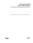
Z80 CMOS Microprocessors Z84C90 KIO Serial/ Parallel Counter/Timer Product Specification PS011804-0612 Copyright ©2012 Zilog, Inc. All rights reserved. www.zilog.com Z84C90 KIO Serial/Parallel Counter/Timer Product Specification ii Warning: DO NOT USE THIS PRODUCT IN LIFE SUPPORT SYSTEMS. LIFE SUPPORT POLICY ZILOG’S PRODUCTS ARE NOT AUTHORIZED FOR USE AS CRITICAL COMPONENTS IN LIFE SUPPORT DEVICES OR SYSTEMS WITHOUT THE EXPRESS PRIOR WRITTEN APPROVAL OF THE PRESIDENT AND GENERAL COUNSEL OF ZILOG CORPORATION. AS USED HEREIN Life support devices or systems are devices which (a) are intended for surgical implant into the body, or (b) support or sustain life and whose failure to perform when properly used in accordance with instructions for use provided in the labeling can be reasonably expected to result in a significant injury to the user. A critical component is any component in a life support device or system whose failure to perform can be reasonably expected to cause the failure of the life support device or system or to affect its safety or effectiveness. DOCUMENT DISCLAIMER ©2012 Zilog, Inc All rights reserved. Information in this publication concerning the devices, applications, or technology described is intended to suggest possible uses and may be superseded. ZILOG, INC. DOES NOT ASSUME LIABILITY FOR OR PROVIDE A REPRESENTATION OF ACCURACY OF THE INFORMATION, DEVICES, OR TECHNOLOGY DESCRIBED IN THIS DOCUMENT. ZILOG ALSO DOES NOT ASSUME LIABILITY FOR INTELLECTUAL PROPERTY INFRINGEMENT RELATED IN ANY MANNER TO USE OF INFORMATION, DEVICES, OR TECHNOLOGY DESCRIBED HEREIN OR OTHERWISE. The information contained within this document has been verified according to the general principles of electrical and mechanical engineering. ZMOTION, Z8 Encore! XP and eZ8 are trademarks or registered trademarks of Zilog, Inc. (An IXYS Company). All other product or service names are the property of their respective owners. PS011804-0612 Life Support Policy Z84C90 KIO Serial/Parallel Counter/Timer Product Specification iii Revision History Each instance in the following revision history table reflects a change to this document from its previous version. For more details, refer to the corresponding pages or appropriate links provided in the table. Revision Level Description Page Number Jun 2013 04 Corrected to remove internal discussion tags. N/A Jun 2012 03 Updated to include missing information covered in the DC8321-00 Databook (2Q94). All Sep 2002 02 Added Z84C90 KIO Peripheral: Serial/Parallel Counter/ Timer Packages table, modified AC Characteristics of the Z84C90 table. 2, 38 Sep 2002 01 Original issue. All Date PS011804-0612 Revision History Z84C90 KIO Serial/Parallel Counter/Timer Product Specification iv Table of Contents Revision History . . . . . . . . . . . . . . . . . . . . . . . . . . . . . . . . . . . . . . . . . . . . . . . . . . . . . . . .iii List of Figures . . . . . . . . . . . . . . . . . . . . . . . . . . . . . . . . . . . . . . . . . . . . . . . . . . . . . . . . . . v List of Tables . . . . . . . . . . . . . . . . . . . . . . . . . . . . . . . . . . . . . . . . . . . . . . . . . . . . . . . . . . vii Introduction . . . . . . . . . . . . . . . . . . . . . . . . . . . . . . . . . . . . . . . . . . . . . . . . . . . . . . . . . . . . 1 Features . . . . . . . . . . . . . . . . . . . . . . . . . . . . . . . . . . . . . . . . . . . . . . . . . . . . . . . . . . . . 1 Block Descriptions . . . . . . . . . . . . . . . . . . . . . . . . . . . . . . . . . . . . . . . . . . . . . . . . . . . . . . 3 Pin Signals . . . . . . . . . . . . . . . . . . . . . . . . . . . . . . . . . . . . . . . . . . . . . . . . . . . . . . . . . . . . . 8 Pin Descriptions . . . . . . . . . . . . . . . . . . . . . . . . . . . . . . . . . . . . . . . . . . . . . . . . . . . . . . . . Register Address Decoding for the KIO . . . . . . . . . . . . . . . . . . . . . . . . . . . . . . . . . . Register Programming . . . . . . . . . . . . . . . . . . . . . . . . . . . . . . . . . . . . . . . . . . . . . . . PIO Registers . . . . . . . . . . . . . . . . . . . . . . . . . . . . . . . . . . . . . . . . . . . . . . . . . . . . . . . . . CTC Registers . . . . . . . . . . . . . . . . . . . . . . . . . . . . . . . . . . . . . . . . . . . . . . . . . . . . . . . . SIO Registers . . . . . . . . . . . . . . . . . . . . . . . . . . . . . . . . . . . . . . . . . . . . . . . . . . . . . . . . . PIA Registers . . . . . . . . . . . . . . . . . . . . . . . . . . . . . . . . . . . . . . . . . . . . . . . . . . . . . . . . . KIO Command Register . . . . . . . . . . . . . . . . . . . . . . . . . . . . . . . . . . . . . . . . . . . . . . . . Z84C90 KIO: Enhanced Version . . . . . . . . . . . . . . . . . . . . . . . . . . . . . . . . . . . . . . . 10 13 16 16 18 20 26 27 27 Electrical Characteristics . . . . . . . . . . . . . . . . . . . . . . . . . . . . . . . . . . . . . . . . . . . . . . . . . Absolute Maximum Ratings . . . . . . . . . . . . . . . . . . . . . . . . . . . . . . . . . . . . . . . . . . . Standard Test Conditions . . . . . . . . . . . . . . . . . . . . . . . . . . . . . . . . . . . . . . . . . . . . . DC Characteristics . . . . . . . . . . . . . . . . . . . . . . . . . . . . . . . . . . . . . . . . . . . . . . . . . . Capacitance . . . . . . . . . . . . . . . . . . . . . . . . . . . . . . . . . . . . . . . . . . . . . . . . . . . . . . . . AC Characteristics . . . . . . . . . . . . . . . . . . . . . . . . . . . . . . . . . . . . . . . . . . . . . . . . . . 29 29 29 30 37 37 Packaging . . . . . . . . . . . . . . . . . . . . . . . . . . . . . . . . . . . . . . . . . . . . . . . . . . . . . . . . . . . . 45 Ordering Information . . . . . . . . . . . . . . . . . . . . . . . . . . . . . . . . . . . . . . . . . . . . . . . . . . . . 46 Part Number Suffix Designations . . . . . . . . . . . . . . . . . . . . . . . . . . . . . . . . . . . . . . . . . 46 Precautions & Limitations . . . . . . . . . . . . . . . . . . . . . . . . . . . . . . . . . . . . . . . . . . . . . . . . 47 Customer Support . . . . . . . . . . . . . . . . . . . . . . . . . . . . . . . . . . . . . . . . . . . . . . . . . . . . . . 49 PS011804-0612 Table of Contents Z84C90 KIO Serial/Parallel Counter/Timer Product Specification v List of Figures Figure 1. A Block Diagram of the Z84C90 KIO Peripheral . . . . . . . . . . . . . . . . . . . . . 2 Figure 2. Z84C20 Parallel Input/Output Block Diagram . . . . . . . . . . . . . . . . . . . . . . . 3 Figure 3. Parallel Interface Adapter Block Diagram . . . . . . . . . . . . . . . . . . . . . . . . . . . 4 Figure 4. Counter/Timer Block Diagram . . . . . . . . . . . . . . . . . . . . . . . . . . . . . . . . . . . 5 Figure 5. SIO Block Diagram . . . . . . . . . . . . . . . . . . . . . . . . . . . . . . . . . . . . . . . . . . . . 6 Figure 6. Crystal Connection . . . . . . . . . . . . . . . . . . . . . . . . . . . . . . . . . . . . . . . . . . . . 7 Figure 7. Z84C90 84-Pin PLCC Configuration . . . . . . . . . . . . . . . . . . . . . . . . . . . . . . 8 Figure 8. 100-Pin LQFP Configuration . . . . . . . . . . . . . . . . . . . . . . . . . . . . . . . . . . . . . 9 Figure 9. KIO Register Addressing . . . . . . . . . . . . . . . . . . . . . . . . . . . . . . . . . . . . . . . 15 Figure 10. PIO Interrupt Vector Word Register . . . . . . . . . . . . . . . . . . . . . . . . . . . . . . 16 Figure 11. PIO Mode Control Word Register . . . . . . . . . . . . . . . . . . . . . . . . . . . . . . . . 16 Figure 12. PIO I/O Register Control Word . . . . . . . . . . . . . . . . . . . . . . . . . . . . . . . . . . 17 Figure 13. PIO Interrupt Control Word . . . . . . . . . . . . . . . . . . . . . . . . . . . . . . . . . . . . . 17 Figure 14. PIO Mask Control Word . . . . . . . . . . . . . . . . . . . . . . . . . . . . . . . . . . . . . . . 18 Figure 15. PIO Interrupt Disable Word . . . . . . . . . . . . . . . . . . . . . . . . . . . . . . . . . . . . . 18 Figure 16. CTC Channel Control Word . . . . . . . . . . . . . . . . . . . . . . . . . . . . . . . . . . . . 19 Figure 17. CTC Time Constant Word . . . . . . . . . . . . . . . . . . . . . . . . . . . . . . . . . . . . . . 20 Figure 18. CTC Interrupt Vector Word . . . . . . . . . . . . . . . . . . . . . . . . . . . . . . . . . . . . . 20 Figure 19. SIO Read Register 0 . . . . . . . . . . . . . . . . . . . . . . . . . . . . . . . . . . . . . . . . . . 21 Figure 20. SIO Read Register 1** . . . . . . . . . . . . . . . . . . . . . . . . . . . . . . . . . . . . . . . . 21 Figure 21. SIO Read Register 2 (Channel B only) . . . . . . . . . . . . . . . . . . . . . . . . . . . . 22 Figure 22. SIO Write Register 0 . . . . . . . . . . . . . . . . . . . . . . . . . . . . . . . . . . . . . . . . . . 23 Figure 23. SIO Write Register 1 . . . . . . . . . . . . . . . . . . . . . . . . . . . . . . . . . . . . . . . . . . 23 Figure 24. SIO Write Register 2 (Channel B only) . . . . . . . . . . . . . . . . . . . . . . . . . . . . 24 Figure 25. SIO Write Register 3 . . . . . . . . . . . . . . . . . . . . . . . . . . . . . . . . . . . . . . . . . . 24 Figure 26. SIO Write Register 4 . . . . . . . . . . . . . . . . . . . . . . . . . . . . . . . . . . . . . . . . . . 25 Figure 27. SIO Write Register 5 . . . . . . . . . . . . . . . . . . . . . . . . . . . . . . . . . . . . . . . . . . 25 Figure 28. SIO Write Register 6 . . . . . . . . . . . . . . . . . . . . . . . . . . . . . . . . . . . . . . . . . . 26 PS011804-0612 List of Figures Z84C90 KIO Serial/Parallel Counter/Timer Product Specification vi Figure 29. SIO Write Register 7 . . . . . . . . . . . . . . . . . . . . . . . . . . . . . . . . . . . . . . . . . . 26 Figure 30. PIA Control Register . . . . . . . . . . . . . . . . . . . . . . . . . . . . . . . . . . . . . . . . . . 27 Figure 31. KIO Command Register A . . . . . . . . . . . . . . . . . . . . . . . . . . . . . . . . . . . . . 27 Figure 32. KIO Register 15: KIO Command Register B . . . . . . . . . . . . . . . . . . . . . . . 28 Figure 33. Test Load Diagram . . . . . . . . . . . . . . . . . . . . . . . . . . . . . . . . . . . . . . . . . . . 30 Figure 34. I/O Read/Write Timing (M1 = 1) . . . . . . . . . . . . . . . . . . . . . . . . . . . . . . . . 31 Figure 35. Interrupt Acknowledge Cycle . . . . . . . . . . . . . . . . . . . . . . . . . . . . . . . . . . . 32 Figure 36. Counter/Timer Timing . . . . . . . . . . . . . . . . . . . . . . . . . . . . . . . . . . . . . . . . . 32 Figure 37. RETI Timing Standard Function . . . . . . . . . . . . . . . . . . . . . . . . . . . . . . . . . 33 Figure 38. RETI Timing Interrupt Pending . . . . . . . . . . . . . . . . . . . . . . . . . . . . . . . . . . 34 Figure 39. Port I/O Read/Write Timing . . . . . . . . . . . . . . . . . . . . . . . . . . . . . . . . . . . . 35 Figure 40. Serial I/O Timing . . . . . . . . . . . . . . . . . . . . . . . . . . . . . . . . . . . . . . . . . . . . . 36 Figure 41. Op Code Fetch Cycle . . . . . . . . . . . . . . . . . . . . . . . . . . . . . . . . . . . . . . . . . . 37 Figure 42. Internal Daisy Chain Configuration . . . . . . . . . . . . . . . . . . . . . . . . . . . . . . . 42 PS011804-0612 List of Figures Z84C90 KIO Serial/Parallel Counter/Timer Product Specification vii List of Tables Table 1. Z84C90 KIO Peripheral: Serial/Parallel Counter/Timer Packages . . . . . . . . 2 Table 2. KIO Registers . . . . . . . . . . . . . . . . . . . . . . . . . . . . . . . . . . . . . . . . . . . . . . . 13 Table 3. DC Characteristics of the Z84C90 . . . . . . . . . . . . . . . . . . . . . . . . . . . . . . . . 30 Table 4. Capacitance . . . . . . . . . . . . . . . . . . . . . . . . . . . . . . . . . . . . . . . . . . . . . . . . . 37 Table 5. AC Characteristics of the Z84C90 . . . . . . . . . . . . . . . . . . . . . . . . . . . . . . . . 38 Table 6. Daisy Chain Parameters . . . . . . . . . . . . . . . . . . . . . . . . . . . . . . . . . . . . . . . . 43 Table 7. Daisy Chain Calculation Data* . . . . . . . . . . . . . . . . . . . . . . . . . . . . . . . . . . 43 Table 8. Z84C90 KIO Ordering Matrix . . . . . . . . . . . . . . . . . . . . . . . . . . . . . . . . . . . 46 PS011804-0612 List of Tables Z84C90 KIO Serial/Parallel Counter/Timer Product Specification 1 Introduction Zilog’s Z84C90 Serial/Parallel Counter/Timer KIO is a multichannel, multipurpose I/O peripheral device designed to provide the end user with a cost-effective and powerful solution to meet an assortment of peripherals requirements. The Z84C90 KIO Peripheral combines the features of one Z84C30 CTC, one Z84C20 PIO and a Z84C4x SIO, plus an 8-bit, bit-programmable I/O port and a crystal oscillator into a single 84-pin PLCC or 100-pin LQFP package. Utilizing fifteen internal registers for data and programming information, the KIO can easily be configured to any given system environment. Although optimum performance is obtained with a Z84C00 CPU, the KIO can just as easily be used with any other CPU. Features The Z84C90 Serial/Parallel Counter/Timer KIO offers the following features: • • • • • • • • • • Two independent synchronous/asynchronous serial channels Three 8-bit parallel ports Four independent counter/timer channels On-chip clock oscillator/driver Software/hardware resets Designed in CMOS for low power operations Supports Z80 Family interrupt daisy chain Programmable interrupt priorities 8, 10 and 12.5 MHz bus clock frequency Single +5 V power supply Table 1 lists the differing frequencies offered for the Z84C90 KIO Peripheral by package and part number. PS011804-0612 Introduction Z84C90 KIO Serial/Parallel Counter/Timer Product Specification 2 Table 1. Z84C90 KIO Peripheral: Serial/Parallel Counter/Timer Packages Part Number Package Frequency (MHz) Z84C9008ASC 100-pin LQFP 8 Z84C9010ASC 100-pin LQFP 10 Z84C9008VEC 84-pin PLCC 8 Z84C9008VSC 84-pin PLCC 8 Z84C9010VSC 84-pin PLCC 10 Z84C9012VSC 84-pin PLCC 12 Figure 1 illustrates a block diagram of the Z84C90 KIO Peripheral. PIO Oscillator MODEM CONTROL Bus Interface and Control INTERRUPT BUS PIA/ MUX CONTROL BUS D0–D7 A0–A3 CS MI RD IORQ RESET CLK PB0–PB7 BRDY BSTB DATA BUS OSC XTAL1 XTAL0 CLKOUT PA0–PA7 ARDY ASTB SIO PC0–PCV RXDA RXCA TXDA TXCA CTSA DCDA RXDB RXCB TXDB TXCB CTSB DCDB ZC/TO0 CLK/TRG0 INT IE1 IE0 Interrupt Control ZC/TO1 CLK/TRG1 CTC ZC/TO2 CLK/TRG2 ZC/TO3 CLK/TRG3 Figure 1. A Block Diagram of the Z84C90 KIO Peripheral PS011804-0612 Features Z84C90 KIO Serial/Parallel Counter/Timer Product Specification 3 Block Descriptions Z84C20 Parallel Input/Output Logic Unit. This logic unit provides both TTL- and CMOS-compatible interfaces between peripheral devices and a CPU through the use of two 8-bit parallel ports. The CPU configures the logic to interface to a wide range of peripheral devices with no external logic. Typical devices that are compatible with this interface are keyboards, printers and EPROM/PAL programmers. The parallel ports (designated Port A and Port B) are byte-wide and completely compatible with the Z84C90 PIO (see Figure 2). These two ports feature several modes of operation: input, output, bidirectional or bit control. Each port features two handshake signals (RDY and STB) which can be used to control data transfers. The RDY (ready) indicates that the port is ready for data transfer while STB (strobe) is an input to the port that indicates when data transfer has occurred. Each of the ports can also be programmed to interrupt the CPU upon the occurrence of specified status conditions and generate unique interrupt vectors when the CPU responds. For more information about the operation of this portion of the logic, please refer to the Z8420/Z84C20 PIO Product Specification (PS0180). Internal Control Logic Data or Control Port A I/O Data CPU Bus I/O Handshake Peripheral Interface Internal Bus Control 8 Port B I/O Data or Control Handshake Interrupt Control 3 Interrupt Control Lines Figure 2. Z84C20 Parallel Input/Output Block Diagram PS011804-0612 Block Descriptions Z84C90 KIO Serial/Parallel Counter/Timer Product Specification 4 Parallel Interface Adapter (PIA) Logic Unit. This logic also offers an additional 8 bits of I/O to the user, referred to as the PIA port (see Figure 3). This port, designated as Port C, is bit-programmable for data transfers; each bit can be individually programmed as either an input or an output. Bit direction control is performed through the programming of the PIA Control Register. When programmed as outputs, the output data latches are programmed with an I/O write cycle; their state can be read with an I/O read cycle. When programmed as inputs, the state of the external pin is read with the I/O read cycle. This port does not have handshake capabilities and offers no interrupt capabilities. This port is multiplexed to provide the additional modem and CPU control signals for the serial I/O logic unit, when appropriate. Port C PC0–PC7 Data Bus Dir. Ctrl. Figure 3. Parallel Interface Adapter Block Diagram When a read from the PIA port occurs, input data will be latched when IORQ, CS and RD all detected as active. The data bus will display this data as a result of the rising edge of the clock input after this occurrence. When a write to the PIA port occurs, data will be written as a result of the rising edge of the clock input after IORQ and CS have been detected as active and RD has been detected as inactive. Counter/Timer Logic (CTC) Unit. This logic unit provides the user with four individual 8-bit counter/timer channels that are compatible with the Z84C30 CTC (see Figure 4). The counter/timers can be programmed by the CPU for a broad range of counting and timing applications. Typical applications include event counting, interrupt and interval timing and serial baud rate clock generation. Each of the counter/timer channels, designated Channels 0 through 3, have an 8-bit prescaler (when used in timer mode) as well as its own 8-bit counter to provide a wide range of count resolution. Each of the channels also have their own clock/trigger input to quantify the counting process and an output to indicate zero crossing/time-out conditions. With only one interrupt vector programmed into this logic unit, each channel can generate a unique interrupt vector in response to the interrupt acknowledge cycle. PS011804-0612 Block Descriptions Z84C90 KIO Serial/Parallel Counter/Timer Product Specification 5 Internal Control Logic Data 8 CPU Bus I/O Control INT IE1 Interrupt Logic Internal Bus IE0 6 Counter/ Timer Logic 4 ZC/TO 4 CLK/TRG Reset Figure 4. Counter/Timer Block Diagram Serial I/O Logic Unit. This logic unit provides the user with two separate serial I/O chan- nels that are completely compatible with the Z84C4x SIO (see Figure 5). Their basic functions as serial-to-parallel and parallel-to-serial converters can be programmed by a CPU for a broad range of serial communications applications. Each channel, designated Channel A and Channel B, is capable of supporting all common asynchronous and synchronous protocols (Monosync, Bisync and SDLC/HDLC), byte- or bit-oriented. PS011804-0612 Block Descriptions Z84C90 KIO Serial/Parallel Counter/Timer Product Specification 6 Data Channel A Control and Status Registers Channel A Serial Data Channel Clocks Sync Wait/Ready Internal Control Logic Channel A Control and Status Modem or Other Control Channel B Control and Status Modem or Other Control Channel B Serial Data Channel Clocks Sync Wait/Ready I n t e r n a l 8 CPU Bus I/O Control 7 B u s Interrupt Control Lines Interrupt Control Logic Channel B Control and Status Registers Figure 5. SIO Block Diagram In the default state of the KIO, each serial channel supports full duplex communication with separate transmit and receive data lines, two modem control signals (CTS and DCD) and separate transmit and receive clock inputs. Optionally, additional modem and CPU/ DMA control signals can be obtained through the PIA port. For more information about the operation of this portion of the logic, please refer to the Z8420/Z84C20 PIO Product Specification (PS0180). PS011804-0612 Block Descriptions Z84C90 KIO Serial/Parallel Counter/Timer Product Specification 7 Clock Oscillator/Driver Logic Unit. A clock oscillator/driver is available that will allow the user to eliminate circuitry with in a new design, or that can be used as another oscillator within the system. This logic will accept either a crystal ceramic resonator or TTLcompatible clock input and generate a MOS-compatible clock output and also an oscillator reference output. Zilog recommends a fundamental parallel resonant crystal; see Figure 6. The preferred value of the two capacitors C1 and C2 is 33 pF each. C1 ZTALI Crystal Inputs C2 XTALO Figure 6. Crystal Connection Command Logic Unit. This logic unit provides for much more than just controlling the interface between the KIO and the CPU. The main function provided by this unit is to allow the user to configure the internal interrupt daisy chain of the KIO into a preferred sequence of peripherals to interrupt. Any one of the three devices (SIO, CTC, PIO) can be the highest priority, while another can be second priority and the remaining device the third. The user can even configure the daisy chain such that no internal peripherals are involved in the chain. Programming of the daisy chain configuration is performed by programming the Command Register with the appropriate 3-bit pattern in addresses D0–D2, with D3 set to 1. A second function of this logic unit is to provide software-controllable hardware resets to each of the individual devices. As a result, an individual peripheral is allowed to be reset without having to reset the entire KIO. Requiring bit D3 to be set to a 1 to program the daisy chain configuration allows the user to reset the individual devices without changing the daisy chain. The software reset commands for the individual devices still remain available to the user. A third function of the Command Register allows the user to obtain use of the additional control signals of the SIO logic instead of the PIA port by programming bit D7 of the Command Register with a 1. PS011804-0612 Block Descriptions Z84C90 KIO Serial/Parallel Counter/Timer Product Specification 8 Pin Signals 11 10 9 8 7 6 5 4 3 2 1 84 83 82 81 80 79 78 77 76 75 PCO (WT/RDY GND CTSA DCDA DCDB CTSB TxDB TxCB RxCB RxDB A0 A1 A2 A3 CS M1 RD VCC IORQ RESET CLK/TRG3 Figure 7 shows the pin-outs for the 84-pin PLCC Z84C90 KIO Peripheral package; Figure 8 shows the 100-pin LQFP pin-outs. 12 13 14 15 16 17 18 19 20 21 22 23 24 25 26 27 28 29 30 31 32 84-Pin PLCC 74 73 72 71 70 69 68 67 66 65 64 63 62 61 60 59 58 57 56 55 54 CLK/TRG2 CLK/TRG1 CLK/TRG0 D7 D6 D5 D4 GND VCC D3 D2 D1 D0 VCC XTAL1 XTAL0 GND CLOCK CLKOUT OSC INT GND GND PB7 PB6 PB5 PB4 PB3 PB2 PB1 PB0 BRDY BSTB ARDY ASTB ZC/TO3 ZC/TO2 ZC/TO1 ZC/TO0 IE1 IE0 VCC 33 34 35 36 37 38 39 40 41 42 43 44 45 46 47 48 49 50 51 52 53 PC1 (SYNCB) PC2 (DTRB) PC3 (RTSB) TxDA TxCA RxCA RxDA PA0 PA1 PA2 VCC PA3 GND PA4 PA5 PA6 PA7 PC4 (RTSA) PC5 (DTRA) PC6 (SYNCA) PC7 (WT/RDYA) Figure 7. Z84C90 84-Pin PLCC Configuration PS011804-0612 Pin Signals Z84C90 KIO Serial/Parallel Counter/Timer Product Specification 75 NC NC 65 60 55 51 50 76 80 45 85 40 100-Pin LQFP 90 35 95 30 26 100 5 10 15 20 NC NC CLK/TRG2 CLK/TRG1 CLK/TRG0 D7 D6 D5 D4 GND VCC D3 D2 D1 D0 VCC XTAL1 XTAL0 GND CLOCK CLKOUT OSC INT 1 NC NC GND GND PB7 PB6 PB5 PB4 PB3 PB2 PB1 PB0 BRDY BSTB ARDY ASTB ZC/TO3 ZC/TO2 ZC/TO1 ZC/TO0 IE1 IE0 VCC NC NC 25 NC NC NC NC PC0 (WT/RDYB) GND CSTA DCDA DCDB CTSB TxDB TxCB RxCB RxDB A0 A1 A2 A3 CS M1 RD VCC IORQ RESET CLK/TRG3 70 NC NC NC NC PC1 (SYNCB) PC2 (DTRB) PC3 (RTSB) TxDA TxCA RxCA RxDA PA0 PA1 PA2 VCC PA3 GND PA4 PA5 PA6 PA7 PC4 (RTSA) PC5 (DTRA) PC6 (SYNCA) PC7 (WT/RDYA) 9 Figure 8. 100-Pin LQFP Configuration PS011804-0612 Pin Signals Z84C90 KIO Serial/Parallel Counter/Timer Product Specification 10 Pin Descriptions A0–A3. Address bus (inputs). Used to select the port/register for each bus cycle. ARDY, BRDY. Port Ready (outputs, active High). These signals indicate that the port is ready for a data transfer. In Mode 0, the signal indicates that the port has data available to the peripheral device. In Mode 1, the signal indicates that the port is ready to accept data from the peripheral device. In Mode 2, ARDY indicates that Port A has data available for the peripheral device, but that the data is not be placed onto PA0–PA7 until the ASTB signal is Active. BRDY indicates that Port A is able to accept data from a peripheral device. Note: Port B does not support Mode 2 operation and can only be used in Mode 3 when Port A is programmed for Mode 2. BRDY is not associated with Port B when it is operating in Mode 3. ASTB, BSTB. Port Strobe (inputs, active Low). These signals indicate that the peripheral device has performed a transfer. In Mode 0, the signal indicates that the peripheral device has accepted the data present on the port pins. In Mode 1, the signal causes the data on the port pins to be latched onto Port A. In Mode 2, ASTB Low causes the data in the output data latch of Port A to be placed onto the Port A pins. BSTB Low causes the data present on the Port A pins to be latched into the Port A input data latch. The end of the current transaction is noted by the rising edge of these signals. Note: Port B does not support Mode 2 operation, and can only be used in Mode 3 when Port A is programmed for Mode 2. BSTB is not associated with Port B when it is operating in Mode 3. CLK/TRG0–CLK/TRG3. External Clock/Timer Trigger (inputs, user-selectable active High or Low). These four pins correspond to the four counter/timer channels of the KIO. In Counter mode, each active edge causes the downcounter to decrement. In Timer mode, an active edge starts the timer. CLKOUT. Clock Out (output). This output is a divide-by-two of the oscillator (XTAL) input. CLOCK. System Clock (input). This clock must be the same as (or a derivative of) the CPU clock. If the CLKOUT is to be used as the system clock, then these two pins must be connected together. PS011804-0612 Pin Descriptions Z84C90 KIO Serial/Parallel Counter/Timer Product Specification 11 CS. Chip Select (input, active Low). Used to activate the internal register decoding mechanism and allow the KIO to perform a data transfer to/from the CPU. CTSA, CTSB. Clear to Send (inputs, active Low). These signals are modem control sig- nals for the serial channels. When programmed for Auto Enable, a Low on these pins enables their respective transmitters. If not programmed as Auto Enable, these pins may be used as general-purpose input signals. D0–D7. Data Bus (bidirectional, active High, tristated). Used for data exchanges between the CPU and the KIO for programming and data transfer. The KIO also monitors the data bus for Return from Interrupt (RETI) instructions to maintain its Interrupt Under Service (IUS) status. DCDA, DCDB. Data Carrier Detect (inputs, active Low). These signals are modem control signals for the serial channels. When programmed for Auto Enable, a Low on these pins enables their respective receivers. If not programmed as Auto Enable, these pins may be used as general-purpose input signals. DTRA, DTRB. Data Terminal Ready (outputs, active Low). These signals are modem control signals for the serial channels. They follow the state programmed into their respective serial channels, and are multiplexed with Port C, bits 5 and 2, respectively. IEI. Interrupt Enable In (input, active High). This signal is used with Interrupt Enable Out (IEO) to form a priority daisy chain when there is more than one interrupt-driven device. A High on this line indicates that no higher-priority device is requesting an interrupt. IEO. Interrupt Enable Out (output, active High). This signal is used with Interrupt Enable In (IEI) to form a priority daisy chain when there is more than one interrupt-driven device. A High on this line indicates that this device is requesting an interrupt, and that no higherpriority device, is not requesting an interrupt. A Low blocks any lower-priority devices from requesting an interrupt. IORQ. Input/Output Request (input, active Low). IORQ is used with RD, A0–A3, and CS to transfer data between the KIO and the CPU. When IORQ, RD, and CS are active Low, the device selected by A0–A3 transfers data to the CPU. When IORQ and CS are active Low, but RD is active High, the device selected by A0–A3 is written into by the CPU. When IORQ and M1 are both active Low, the KIO may respond with an interrupt vector from its highest-priority interrupting device. M1. Machine Cycle 1 (input, active Low). When M1 and RD are Low, the Z80 CPU fetches an instruction from memory; the KIO decodes this cycle to determine if the RETI instruction sequence is being executed. When M1 and IORQ are both active, the KIO decodes the cycle to be an interrupt acknowledge, and may respond with a vector from its highest-priority interrupting device. PS011804-0612 Pin Descriptions Z84C90 KIO Serial/Parallel Counter/Timer Product Specification 12 OSC. Oscillator (output). This output is a reference clock for the oscillator. PA0–PA7. Port A Bus (bidirectional, tristated). One of the 8-bit ports of the PIO. PA0 is the least-significant bit of the bus. PB0–PB7. Port B Bus (bidirectional, tristated). One of the 8-bit ports of the PIO. PB0 is the least-significant bit of the bus. This port can also supply 1.5mA at 1.5V to drive Darlington transistors. PC0–PC7. Port C Bus (bidirectional, tristated). PC0 is the least-significant bit of the bus. These pins are multiplexed between the 8-bit PIA and additional modem control signals for the serial channels. RD. Read (input, active Low). When RD is active, a memory or I/O read operation is in progress. RD is used with A0–A3, CS and IORQ to transfer data between the KIO and CPU. RESET. Reset (input, active Low). A Low on this pin forces the KIO into a Reset condi- tion. This signal must be active for a minimum of three clock cycles. When the KIO is reset, the following events occur: • • • • • • The PIO ports are in Mode 1 operation Handshakes are inactive and interrupts are disabled The PIA port is in Input mode and active CTC channel counting is terminated and interrupts are disabled SIO channels are disabled Marking with interrupts is disabled All control registers must be rewritten after a hardware reset. RTSA, RTSB. Request to Send (outputs, active Low). These signals are modem control signals for their serial channels. They follow the inverse state programmed into their respective serial channels, and are multiplexed with Port C, bits 4 and 3, respectively. RxCA, RxCB. Receive Clock (inputs, active Low). These clocks are used to assemble the data in the receiver shift register for their serial channels. Data is sampled on the rising edge of the clock. RxDA, RxDB. Receive Data (inputs, active High). These pins are the input data pins to the receive shift register for their serial channels. SYNCA, SYNCB. Synchronization (bidirectional, active Low). In the Asynchronous mode of operation, these pins act much like the CTS and DCD pins. Transitions affect the Sync/ PS011804-0612 Pin Descriptions Z84C90 KIO Serial/Parallel Counter/Timer Product Specification 13 Hunt status bit for their respective serial channels, but serve no other purpose. These pins are multiplexed with Port C, bits 6 and 1, respectively. TxCA, TxCB. Transmit Clock (inputs, active Low). These clocks are used to transmit data from the transmit shift register for their serial channels. Data is transmitted on the falling edge of the clock. TxDA, TxDB. Transmit Data (outputs, active High). These pins are the output data pins from the transmitter for their serial channels. WT/RDYA, WT/RDYB. Wait/Ready (outputs, open-drain when programmed as Wait; tristated when programmed as Ready). These pins may be programmed as Ready lines for a DMA controller or Wait lines for interfacing to a CPU. As a Ready line, these pins indicate (when active Low) that the transmitter or the receiver requests a transfer between the serial channel and the DMA. As a Wait line, these pins dictate (when Low) that the CPU must wait until the transmitter or receiver can complete the requested transaction. These pins are multiplexed with Port C, bit 7 and 0, respectively. XTALI. Crystal/Clock Connection. (input). XTALO. Crystal Connection. (output). ZC/TO0–ZC/TO3. Zero count/Time-Out (outputs, active High). These four pins are out- puts from the four counter/timer channels of the KIO. Each pin pulses High when its corresponding downcounter reaches 0. Register Address Decoding for the KIO Address lines A0–A3 determine which one of the 16 control registers is being accessed. Table 2 shows the address decoding of each of the KIO control registers; also see Figure 9 on page 15. Table 2. KIO Registers Address A3 A2 A1 A0 Register 0: PIO Port A Data 0 0 0 0 Register 1: PIO Port A Command 0 0 0 1 Register 2: PIO Port B Data 0 0 1 0 Register 3: PIO Port B Command 0 0 1 1 Register 4: CTC Channel 0 0 1 0 0 Note: Additionally, IORQ and CS must be Low. Registers are written to or read from by the CPU, applying a 1 or a 0 respectively on the RD pin. PS011804-0612 Register Address Decoding for the KIO Z84C90 KIO Serial/Parallel Counter/Timer Product Specification 14 Table 2. KIO Registers (Continued) Address A3 A2 A1 A0 Register 5: CTC Channel 1 0 1 0 1 Register 6: CTC Channel 2 0 1 1 0 Register 7: CTC Channel 3 0 1 1 1 Register 8: SIO Port A Data 1 0 0 0 Register 9: SIO Port A Command/Status 1 0 0 1 Register 10: SIO Channel B Data 1 0 1 0 Register 11: SIO Channel B Command/Status 1 0 1 1 Register 12: PIA Port C Data 1 1 0 0 Register 13: PIA Port C Command 1 1 0 1 Register 14: KIO Command 1 1 1 0 Register 15: KIO Command B 1 1 1 1 Note: Additionally, IORQ and CS must be Low. Registers are written to or read from by the CPU, applying a 1 or a 0 respectively on the RD pin. PS011804-0612 Register Address Decoding for the KIO Z84C90 KIO Serial/Parallel Counter/Timer Product Specification 15 Figure 9. KIO Register Addressing PS011804-0612 Register Address Decoding for the KIO Z84C90 KIO Serial/Parallel Counter/Timer Product Specification 16 Register Programming This section describes how the bits within each of the Z84C90 KIO’s command registers change their respective command register functions, as well as the effects of such changes. PIO Registers The PIO registers described in this section apply to channels A and B (additionally, see the Register Address Decoding for the KIO section on page 13). For more information about these PIO registers, please consult the Z80 CPU Peripherals User Manual (UM0081). Interrupt Vector Word. When Bit 0 of the command register is cleared to 0, the command register functions as the Interrupt Vector Word Register. The PIO logic unit is designed to work with the Z80 CPU in Interrupt Mode 2. This word must be programmed if interrupts are to be used; bit D0 must be 0. See Figure 10. V7 V6 V5 V4 V3 V2 V1 V0 Identifies interrupt vector User-supplied interrupt vector Figure 10. PIO Interrupt Vector Word Register Mode Control Word. When bits B2 to B0 are set to 1, the command register functions as the Mode Control Word Register. Selects the port operating mode. This word is required and can be written at any time. See Figure 11. D7 D6 D5 D4 1 1 1 1 Identifies mode control word Don’t care Mode Select 0 0 Mode 0 0 1 Mode 1 1 0 Mode 2 1 1 Mode 3 Figure 11. PIO Mode Control Word Register PS011804-0612 Register Programming Z84C90 KIO Serial/Parallel Counter/Timer Product Specification 17 I/O Register Control Word. When Mode 3 is selected, the Mode Control Word data must be followed by the loading of the I/O Register Control Word data. This word configures the I/O Register, which defines which port lines are inputs or outputs. A 1 indicates input, while a 0 indicates output. this word is required with in Mode 3. See Figure 12. I/O7 I/O6 I/O5 I/O4 I/O3 I/O2 I/O1 I/O0 0: Sets bit to output 1: Sets bit to input Figure 12. PIO I/O Register Control Word PIO Interrupt Control Word. When bits D3 to D0 are loaded with 0111, the command register functions as the PIO Interrupt Control Word Register. In Mode 3 operation, handshake signals are not used. Interrupts are generated as a logic function of the input signal levels. The Interrupt Control Word sets the logic conditions and the logic levels required for generating an interrupt. Two logic conditions or functions are available: AND (if all input bits change to the active level, an interrupt is triggered) and OR (if any one of the input bits change to the active logic level, an interrupt is triggered). The user can also program which input bits are to be considered as part of this logic function. bit D6 sets the logic function, bit D5 sets the logic level and bit D4 specifies the mask control word data to follow. See Figure 13. D7 1 D0 H/L 0 1 1 1 Identifies interrupt control word 1 = Mask follows1 1 = Active High 1 = AND function 1 = Interrupt Function Enable2 Notes: 1. Regardless of the operating mode, setting bit D4 = 1 causes any pending interrupts to be cleared. 2. The port interrupt is not enabled until the interrupt function enable is followed by an active M1. Figure 13. PIO Interrupt Control Word Mask Control Word. This words sets the Mask Control Register, thus allowing any unused bits to be masked off. If any bits are to be masked, bit D4 of the Interrupt Control PS011804-0612 Register Programming Z84C90 KIO Serial/Parallel Counter/Timer Product Specification 18 Word must be set. When bit D4 of the Interrupt Control Word is set, the next word loaded into the command register must be the Mask Control Word. To mask an input bit, the corresponding Mask Control Word bit must be a 1. See Figure 14. D7 D6 D5 D4 D3 D2 D1 D0 MB0-MB7 Mask Bits A bit is monitored for an interrupt if it is defined as an input and the mask bit is set to 0. Figure 14. PIO Mask Control Word Interrupt Disable Word. When bits B3 to B0 are loaded with 0011, the command register functions as the Interrupt Disable Word Register. This word can be used to enable or disable a port’s interrupts without change the remainder of the port’s interrupt conditions. See Figure 15. D7 D6 D5 D4 0 0 1 1 Identifies interrupt disable word 1 = Don’t care 0 = Interrupt disable 1 = Interrupt enable Figure 15. PIO Interrupt Disable Word CTC Registers The CTC registers apply to channels 0, 1, 2 and 3 (additionally, see the Register Address Decoding for the KIO section on page 13). For more information about these CTC registers, please consult the Z80 CPU Peripherals User Manual (UM0081). Channel Control Word. This word sets the operating modes and parameters as described in the following paragraphs. Bit D0 of the CTC Register must be a 1 to indicate a Control Word; otherwise, it is an Interrupt Vector Word. See Figure 16. PS011804-0612 Register Programming Z84C90 KIO Serial/Parallel Counter/Timer Product Specification 19 D7 D6 D5 D4 0 0 1 1 Interrupt 1 = Enable interrupt 0 = Disables interrupt Control or vector 0 = Vector 1 = Control word Mode 0 = Selects timer mode 1 = Selects counter mode Reset 0 = Continued operation 1 = Software reset Prescaler Value* 0 = Value of 16 1 = Value of 256 Time Constant 0 = No time constant follows 1 = Time constant follows CLK/TRG Edge Selection 0 = Selects Falling Edge 1 = Selects Rising Edge Timer Trigger* 0 = Automatic trigger when time constant is loaded 1 = CLK/TRG pulse starts timer Figure 16. CTC Channel Control Word Interrupt Enable. Bit D7 enables the interrupt logic so that an interrupt output (INT) can be generated at zero count. Interrupts can be programmed in either mode and can be enabled or disabled at any time. Mode. Bit D6 selects either Timer Mode or Counter Mode. Prescale Factor. Bit D5 selected the prescale factor for use in Timer Mode. Either divideby-16 or divide-by-256 is available. Clock/Trigger Edge Selector. Bit D4 selects the active edge of the CLK/TRG input pulses. Timer Trigger. Bit D3 selects the trigger mode for timer operation. Either an automatic or an external trigger can be selected. Time Constant. Bit D2 indicates that the next word loaded into this register is the time constant data for the downcounter. Software Reset. Setting bit D1 indicates a software reset operation. Time Constant Word. Before a channel can start counting, it must receive a time constant word. The time constant value can be anywhere between 1 and 256, with 0 being accepted as a count of 256. See Figure 17. PS011804-0612 Register Programming Z84C90 KIO Serial/Parallel Counter/Timer Product Specification 20 D7 D6 D5 D4 D3 D2 D1 D0 TC7 TC0 TC6 TC5 TC4 TC1 TC2 TC3 Figure 17. CTC Time Constant Word Interrupt Vector Word. If one or more of the CTC channels have interrupts enabled, the Interrupt Vector Word must be programmed into the CTC Register. Only the five most significant bits of this word are programmed, and bit D0 must be 0. Bits D2–D1 are automatically modified by the CTC channel when it responds with an interrupt vector. See Figure 18. D7 Supplied by user D6 D5 D4 D3 D2 D1 D0 0 = Interrupt vector word 1 = Control word Channel identifier (automatically inserted by CTC) 0 0 = Channel 0 0 1 = Channel 1 1 0 = Channel 2 1 1 = Channel 3 Figure 18. CTC Interrupt Vector Word SIO Registers These registers apply to channels A and B (additionally, see the Register Address Decoding for the KIO section on page 13). The Command/Status Register initially functions as Write Register 0 (WR0) and operates as a pointer to the read registers or to the write registers. The read register for Write Register 0 is RR0. The read registers for Write Register 1 and Write Register 2 are RR1 and RR2, respectively. For more information about these SIO registers, please consult the Z80 CPU Peripherals User Manual (UM0081). PS011804-0612 Register Programming Z84C90 KIO Serial/Parallel Counter/Timer Product Specification 21 Read Registers. SIO Channel B contains three read registers while Channel A contains only two that can be read to obtain status information. To read the contents of a register (other than RR0), the program must first write a pointer to WR0 in exactly the same manner as a write register operation. The next I/O read cycle will place the contents of the selected read register onto the data bus. See Figures 19 through 21. D7 D6 D5 D4 D3 D2 D1 D0 Rx character available Interrupt pending (Ch. A only) Tx buffer empty DCD Sync/Hunt CTS * Tx Underrun/EOM Break/Abort Note: *Used with External/Status Interrupt modes. Figure 19. SIO Read Register 0 D7 D6 D5 D4 D3 D2 D1 D0 All sent 1 0 1 0 1 0 1 0 0 1 1 0 0 1 1 0 0 0 0 1 1 1 1 0 Field bits in previous byte Field bits in second previous byte 0 0 0 0 0 0 1 2 3 4 5 6 7 8 8 8 * Parity error Rx overrun error CRC/Framing error End of frame (SDLC) Notes: *Residue data for eight Rx bits/character programmed. **Used with a special receive condition mode. Figure 20. SIO Read Register 1** PS011804-0612 Register Programming Z84C90 KIO Serial/Parallel Counter/Timer Product Specification 22 D7 D6 D5 D4 D3 D2 D1 D0 V0 V1* V2* V3* V4 V5 V6 V7 Interrupt vector Note: *Variable if Status Affects Vector is also programmed. Figure 21. SIO Read Register 2 (Channel B only) Write Registers. SIO Channel B contains eight write registers while Channel A contains only seven that are programmed to configure the operating modes and characteristics of each channel. With the exception of WR0, programming the write registers is a two-step operation. The first operation is a pointer written to WR0 that points to the selected register. The second operation is the actual control word data that is written into the register to configure the SIO channel. See Figures 22 through 29 to examine the details of these write registers. PS011804-0612 Register Programming Z84C90 KIO Serial/Parallel Counter/Timer Product Specification 23 D7 D6 D5 D4 D3 D2 D1 0 1 1 0 0 1 1 0 1 0 1 0 1 0 1 0 0 0 1 1 0 1 0 1 1 0 1 0 1 0 1 0 1 0 1 0 1 0 1 0 0 0 0 1 1 1 1 0 D0 0 0 0 1 1 1 1 0 Register 0 Register 1 Register 2 Register 3 Register 4 Register 5 Register 6 Register 7 Null code Send abort (SDLC) Reset Ext/Status interrupts Channel reset Enable interrupt on next Rx character Reset TxINT pending Error reset Return from interrupt (Channel A only) Null code Reset Rx CRC checker Reset Tx CRC generator Reset Tx Underrun/EOM latch Figure 22. SIO Write Register 0 D7 D6 D5 D4 D3 D2 D1 D0 External interrupt enable Tx interrupt enable Status affects vector (Channel B only) 0 0 1 1 0 1 0 1 Rx interrupt disable Rx interrupt on first character Interrupt on all Rx characters (parity affects vector) Interrupt on all Rx characters (parity does not affect vector) * WAIT/READY on R/T WAIT/READY function WAIT/READY enable Note: *Or on special condition. Figure 23. SIO Write Register 1 PS011804-0612 Register Programming Z84C90 KIO Serial/Parallel Counter/Timer Product Specification 24 D7 D6 D5 D4 D3 D2 D1 D0 V0 V1 V2 V3 V4 V5 V6 V7 Interrupt vector Figure 24. SIO Write Register 2 (Channel B only) D7 D6 D5 D4 D3 D2 D1 D0 Rx enable Sync character load inhibit Address search mode (SDLC) Rx CRC enable Enter hunt phase Auto enables 0 0 1 1 0 1 0 1 Rx 5 bits/character Rx 7 bits/character Rx 6 bits/character Rx 8 bits/character Figure 25. SIO Write Register 3 PS011804-0612 Register Programming Z84C90 KIO Serial/Parallel Counter/Timer Product Specification 25 D7 D6 D5 D4 D3 D2 D1 D0 Parity enable Parity even/odd 0 0 1 1 0 0 1 1 0 0 1 1 0 1 0 1 0 1 0 1 0 1 0 1 Sync modes enable 1 stop bit/character 1½ stop bits/character 2 stop bits/character 8-bit sync character 16-bit sync character SDLC mode (01111110 flag) External sync mode X1 clock mode X16 clock mode X32 clock mode X64 clock mode Figure 26. SIO Write Register 4 D7 D6 D5 D4 D3 D2 D1 D0 Tx CRC enable RTS SDLC/CRC-18 Tx enable Send break 0 0 1 1 0 1 0 1 Tx 5 bits or less per character Tx 7 bits per character Tx 6 bits per character Tx 8 bits per character DTR Figure 27. SIO Write Register 5 PS011804-0612 Register Programming Z84C90 KIO Serial/Parallel Counter/Timer Product Specification 26 D7 D6 D5 D4 D3 D2 D1 D0 Sync bit 0 Sync bit 1 Sync bit 2 Sync bit 3 Sync bit 4 Sync bit 5 Sync bit 6 Sync bit 7 * Note: *Also SDLC address field. Figure 28. SIO Write Register 6 D7 D6 D5 D4 D3 D2 D1 D0 Sync bit 8 Sync bit 9 Sync bit 10 Sync bit 11 * Sync bit 12 Sync bit 13 Sync bit 14 Sync bit 15 Note: For SDLC, these bits must be programmed to 01111110 for flag recognition. Figure 29. SIO Write Register 7 PIA Registers The PIA port can be configured for any combination of input and output bits. The direction is controlled by writing to the PIA Control Register. A 1 written to a bit position indicates that the respective bit should be an input (see Figure 30). All bits are inputs upon reset. PS011804-0612 Register Programming Z84C90 KIO Serial/Parallel Counter/Timer Product Specification 27 I/O7 I/O6 I/O5 I/O4 I/O3 I/O2 I/O1 I/O0 0 = Sets bit to output 1 = Sets bit to input Figure 30. PIA Control Register KIO Command Register Command Register A is used to program software resets and to configure the internal interrupt daisy chain priority (see Figure 31). This register should be programmed before all others. The reset control bits are momentary; writing a 1 pulses an internal reset signal to the appropriate device. D7 D6 D5 D4 D3 D2 D1 D0 Daisy Chain Configuration 000 None 001 SIO, CTC, PIO 010 SIO, PIO, CTC 011 CTC, SIO, PIO 100 CTC, PIO, SIO 101 PIO, SIO, CTC 110 PIO, SIO, CTC 111 None Daisy chain write enable Reset PIO Reset CTC Reset SIO SIO/PIA mux 0 = PIA 1 = SIO Figure 31. KIO Command Register A Z84C90 KIO: Enhanced Version A subsequent revision of the Z84C90 MCU features an enhancement which allows users to simulate the Return From Interrupt sequence with software. This feature allows the interfacing of the CPU to other devices in addition to the Z80 CPU (or the Z180/Z280). PS011804-0612 Z84C90 KIO: Enhanced Version Z84C90 KIO Serial/Parallel Counter/Timer Product Specification 28 Command Register B. Writing a 1 to a particular command bit location of the KIO generates a RETI sequence internally. Every time a RETI is required, a 1 is written to this bit to allow software control of the RETI. Programming of this Feature. This revision has one newly assigned register at Register Address 15 (this location is reserved on the original version). The bit assignments for this register are shown in Figure 32. D7 D6 D5 D4 D3 D2 D1 D0 Software RETI (write only) Reserved Figure 32. KIO Register 15: KIO Command Register B Writing a 1 to the bit D0 location of this register enables the KIO to simulate a RETI sequence. Writing a 0 to this bit yields no effect. The upper 7 bits of this register (D7–D1) are reserved and should be programmed to 0. If this register is read, unpredictable data is returned. Notes: After writing a 1 to this bit, 8 clock cycles of access recovery time is required before additional access to the KIO can occur. If accessing the KIO within this recovery period, the KIO ignores the transaction on the bus. When simulating RETI, the status of the IEI pin is ignored with an internally forced H. If there are other peripherals on the upper interrupt daisy chain, caution must be exercised. PS011804-0612 Z84C90 KIO: Enhanced Version Z84C90 KIO Serial/Parallel Counter/Timer Product Specification 29 Electrical Characteristics The data in this chapter represents all known data prior to qualification and characterization of the Z84C90 KIO device and is therefore subject to change. Additional electrical characteristics can be found in the individual chapters of this document. Absolute Maximum Ratings Stresses greater than those listed under Absolute Maximum Ratings may cause permanent damage to the device. This rating is a stress rating only. Operation of the device at any condition above those indicated in the operational sections of these specifications is not implied. Exposure to absolute maximum rating conditions for extended periods may affect device reliability. Voltage on VCC with respect to VSS –0.3V to +7.0V Voltages on all inputs with respect to VSS –0.3V to VCC +0.3V Operating Ambient Temperature See Ordering Information Storage Temperature –65°C to +150°C Standard Test Conditions The DC Characteristics and Capacitance sections that follow apply to the following standard test conditions, unless otherwise noted. All voltages are referenced to GND (0V). Positive current flows into the referenced pin. Available operating temperature ranges are: • • S = 0°C to +70°C E = –40°C to +100°C Voltage Supply Range: +5.0V ± 10% All AC parameters assume a load capacitance of 100 pF, as shown in Figure 33. Add a 10 ns delay for each 50 pF increase in load up to a maximum of 200 pF for the data bus and 100 pF for the address and control lines. AC timing measurements are referenced to 1.5 volts (except for CLOCK, which is referenced to the 10% and 90% points. PS011804-0612 Electrical Characteristics Z84C90 KIO Serial/Parallel Counter/Timer Product Specification 30 +5V 2.1K From Output Under Test 100 pF 250 A Figure 33. Test Load Diagram DC Characteristics Table 3 lists the direct current characteristics for the Z84C90 KIO Peripheral. In this table, VCC = 5.0 V ± 10% unless otherwise specified. Table 3. DC Characteristics of the Z84C90 Symbol Item Min Max Unit VILC Clock Input Low Voltage –0.3 +0.45 V VIHC Clock Input High Voltage VCC – 0.6 VCC + 0.3 V VIL Input Low Voltage –0.3 +0.8 V VIH Input High Voltage 2.2 VCC V VOL Output Low Voltage +0.4 V IOL = 2.0mA VOH1 Output High Voltage 1 2.4 V IOH = –1.6mA VOH2 Output High Voltage 2 VCC – 0.8 V IOH = –250mA ILI Input Leakage Current ±10.0 µA VIN = 0.4~VCC IOL 3-State Leakage Current ±10.0 µA VIN = 0.4~VCC IL(SY) SYNC Pin Leakage Current +10 µA VIN = 0.4~VCC –40 Condition Note: *Measurement made with output floating over specified temperature and voltage ranges with VCC = 5 V, VIH = VCC – 0.2 V and VIL = 0.2 V. PS011804-0612 DC Characteristics Z84C90 KIO Serial/Parallel Counter/Timer Product Specification 31 Table 3. DC Characteristics of the Z84C90 (Continued) Symbol Item Min IOHD Darlington Drive Current (Port B and ZC/T00~3) –1.5 ICC Power Supply Current* Max Unit Condition mA VOH = 1.5 V REXT = 390 Ω 8 MHz 15 mA 10 MHz 15 mA 12.5 MHz 15 mA Note: *Measurement made with output floating over specified temperature and voltage ranges with VCC = 5 V, VIH = VCC – 0.2 V and VIL = 0.2 V. Figure 34 shows the timing of reads and writes for the Z84C90 KIO Peripheral’s I/O block. 1 Clock 2 3 5 4 A0–A3 CS 6 7 8 15 IORQ 6 7 8 10 RD 10 Read Cycle 9 D0–D7 RD 12 11 Write Cycle D0–D7 WT/RDY Wait Mode WT/RDY Ready Mode 47 48 49 48 Figure 34. I/O Read/Write Timing (M1 = 1) PS011804-0612 DC Characteristics Z84C90 KIO Serial/Parallel Counter/Timer Product Specification 32 Figure 35 shows the timing of the Z84C90 KIO Peripheral’s interrupts. Twa* Twa* T2 T1 T4 T3 Clock 36 INT 17 16 M1 11 7 IORQ 14 13 D0–D7 19 IE1 18 IE0 *Wait state. Figure 35. Interrupt Acknowledge Cycle Figure 36 shows the timing of the Z84C90 KIO Peripheral’s counter/timer. Clock 40 41 42 CLK/TRG Counter 37 43 44 CLK/TRG Timer 38 46 45 ZC/TO 39 36 INT Figure 36. Counter/Timer Timing PS011804-0612 DC Characteristics Z84C90 KIO Serial/Parallel Counter/Timer Product Specification 33 Figure 37 shows the timing for the RETI sequence. ED Op Code Fetch 1 T4 T1 T2 T3 4D Op Code Fetch 2 T4 T1 T2 T3 T4 T1 Clock 74 M1 74 RD 12 DATA 73 IEI 22 71 IEO Figure 37. RETI Timing Standard Function Figure 38 shows the interrupt timing that occurs when a RETI sequence is pending. PS011804-0612 DC Characteristics Z84C90 KIO Serial/Parallel Counter/Timer Product Specification 34 ED Op Code Fetch 1 T4 T1 T2 4D Op Code Fetch 2 T3 T4 T1 T2 T3 T4 T1 Clock 74 M1 74 RD 12 DATA 73 IEI 22 71 IEO 72 Figure 38. RETI Timing Interrupt Pending Figure 39 shows the read and write timing of the Z84C90 KIO Peripheral’s GPIO ports. PS011804-0612 DC Characteristics Z84C90 KIO Serial/Parallel Counter/Timer Product Specification 35 Clock IORQ RD 34 Port C Input 35 Port C Output 24 23 25 RDY 27 26 STB 28 Mode 0 29 8 Mode 1 31 30 Mode 2 Mode 3 32 33 INT Figure 39. Port I/O Read/Write Timing Figure 40 shows the serial timing of the Z84C90 KIO Peripheral’s I/O block. PS011804-0612 DC Characteristics Z84C90 KIO Serial/Parallel Counter/Timer Product Specification 36 CTS DCD SYNC 52 50 51 TxC 57 53 54 55 56 TxD 58 WT/RDY 59 INT 60 RxC 62 61 65 66 63 64 RxD 67 WT/RDY 68 INT 70 SYNC Figure 40. Serial I/O Timing Figure 41 shows the Z84C90 KIO Peripheral operation code fetch timing. PS011804-0612 DC Characteristics Z84C90 KIO Serial/Parallel Counter/Timer Product Specification 37 Clock 17 16 74 M1 73 74 RD 73 12 D0–D7 22 IE1 20 71 21 72 IE0 Figure 41. Op Code Fetch Cycle Capacitance Table 4 lists the clock and input/output capacitance values for the Z84C90 KIO Peripheral. Table 4. Capacitance Symbol Parameter CCLOCK Minimum Maximum Unit Clock Capacitance 10 cF CIN Input Capacitance 10 cF COUT Output Capacitance 15 cF Note: TA = 25°C, f = 1 MHz. AC Characteristics Table 5 lists the alternating current characteristics for the Z84C90 KIO Peripheral. PS011804-0612 Capacitance Z84C90 KIO Serial/Parallel Counter/Timer Product Specification 38 Table 5. AC Characteristics of the Z84C90 8 MHz No. Symbol Parameter 10 MHz1,6 12.5 MHz1,6 Min Max Min Max Min Max U/M Bus Interface Timing 1 TcC Clock Cycle Time 125 DC 100 DC 80 DC ns 2 TwCh Clock Pulse Width (High) 55 DC 42 DC 32 DC ns 3 TwCl Clock Pulse Width (Low) 55 DC 42 DC 32 DC ns 4 TfC Clock Fall Time 10 10 10 ns 5 TrC Clock Rise Time 10 10 10 ns 6 TsA(Rlf) Address, CS Setup to RD, IORQ Fall 50 40 30 ns 7 TsRl(Cr) RD, IORQ to ClockRise Setup 50 50 40 ns 8 Th Hold Time for Specified Setup 15 15 15 ns 9 TdCr(DO) CLOCK Rise to Data Out Delay 100 80 65 ns 10 TdRlr(DOz) RD, IORQ Rise to Data Out Float Delay 75 60 55 ns 11 M1,RD,IORQ Rise to Data Float 15 15 15 ns 12 TsD(Cr) Data in to Clock Rise Setup 30 25 22 ns 13 TdIOI(DOI) IORQ Fall to Data Out Delay (INTACK Cycle)2 14 ThIOr(D) IORQ Rise to Data Float (INTACK) 15 15 15 ns 15 THIOr(A) IORQ Rise to Address Hold 15 15 15 ns 16 TsM1f(Cr) M1 Fall to Clock Rise Setup 40 40 40 ns 17 TsM1r(Cf) M1 Rise to Clock Fall Setup (M1 Cycle) –15 –15 –15 ns 18 TdM1f(IEOf) M1 Fall to IEO Fall Delay (Interrupt Immediately preceding M1 Fall)3 – – – ns 19 TsIEI(IOf) IEI to IORQ Fall Setup3 ThRDr(D) 95 95 95 ns ns Notes: 1. Maximum SIO data rate is fCLOCK ÷ by 5, in which fCLOCK = 1 ÷ TCC. 2. For a Z80 CPU operating above 8 MHz, one wait state is required to meet this parameter. 3. These daisy chain parameters include contributions from the PIO, SIO and CTC cells, and vary slightly depending on how they are ordered by the KIO Command Register. 4. Counter mode only; when using a cycle time less than 3 TcC, parameter #37 must be met. 5. Units are TcC. 6. If the CPU is a Z80 CPU and if it is required to have multiple Z80 peripherals in the system, then the time period between M1 to IORQ must be extended. 7. Any open-drain output must add a Register-Capacitor (RC) time constant to the specification value. PS011804-0612 AC Characteristics Z84C90 KIO Serial/Parallel Counter/Timer Product Specification 39 Table 5. AC Characteristics of the Z84C90 (Continued) 8 MHz No. Symbol Parameter Min Max 10 MHz1,6 12.5 MHz1,6 Min Min Max Max U/M Bus Interface Timing (continued) 20 TdIEIf(IEOf) IEI Fall to IEO Fall Delay3 160 150 125 ns 21 TdIEIf(IEOr) IEI Rise to IEO Rise Delay (after ED Decode)3 160 150 125 ns 22 TsIEI(Cf) IEI to Clock Fall Setup (for 4D Decode) 50 40 30 ns 23 TsIOr(Cf) IORQ Rise to Clock Fall Setup (to activate RDY on next clock) 100 100 100 ns PIO Timing 24 TdCf(RDYr) Clock Fall to RDY Rise Delay 100 100 25 TdCf(RDYf) ClockFall to RDYFall Delay 100 100 26 TwSTB STB Pulse Width 100 80 27 TsSTBr(Cf) STBRise to ClockFall Setup (to activate RDY on next clock cycle) 100 100 28 TdIOf(PD) IORQFall to Port Data Valid (Mode 0) 29 TsPD(STBr) Port A,B Data to STB Rise Setup Time (Mode 1) 30 TdSTBI(PD) STB Fall to Port A,B Data Valid Delay (Mode 2) 150 120 110 ns 31 TdSTBr(PDz) STB Rise to Port Data Float Delay (Mode 2) 140 120 110 ns 32 TdPD(INTf) Port Data Match to INT Fall Delay (Mode 3) 250 200 160 ns 33 TdSTBr(INTf) STB Rise to INT Fall Delay 290 220 190 ns 34 TsPD(RIf) PIA Port Data to RD, IORQ Fall Setup TBD – 140 140 TBD 100 ns 60 ns ns 120 75 TBD ns 110 75 ns ns Notes: 1. Maximum SIO data rate is fCLOCK ÷ by 5, in which fCLOCK = 1 ÷ TCC. 2. For a Z80 CPU operating above 8 MHz, one wait state is required to meet this parameter. 3. These daisy chain parameters include contributions from the PIO, SIO and CTC cells, and vary slightly depending on how they are ordered by the KIO Command Register. 4. Counter mode only; when using a cycle time less than 3 TcC, parameter #37 must be met. 5. Units are TcC. 6. If the CPU is a Z80 CPU and if it is required to have multiple Z80 peripherals in the system, then the time period between M1 to IORQ must be extended. 7. Any open-drain output must add a Register-Capacitor (RC) time constant to the specification value. PS011804-0612 AC Characteristics Z84C90 KIO Serial/Parallel Counter/Timer Product Specification 40 Table 5. AC Characteristics of the Z84C90 (Continued) 8 MHz No. Symbol Parameter Min Max 10 MHz1,6 12.5 MHz1,6 Min Min Max Max U/M 80 ns PIO Timing (continued) 35 TdCr(PD) Clock Rise to Port Data Valid Delay 80 80 36 TdCr(INTf) Clock Rise to INT Rise Delay TcC+100 37 TsCTRr(Cr)c CLK/TRG Rise to Clock Rise Setup (for immediate count, Counter mode) 90 90 75 ns 38 TsCTRr(Cr)t CLK/TRG Rise to Clock Rise Setup (for enabling prescaler on following ClockRise, Timer mode) 90 90 75 ns 39 TdCTRr(INTf) CLK/TRG Rise to INT Fall Delay TsCTRr(Cr) satisfied TsCTRr(Cr) not satisfied (36)+(38) (36)+(38) (36)+(38) (1)+(36)+(38) (1)+(36)+(38) (1)+(36)+(38) 40 TcCTR CLK/TRG Cycle Time4 (2TcC) DC (2TcC) DC (2TcC) DC ns 41 TwCTRh CLK/TRG Width High 90 DC 90 DC 75 DC ns 42 TwCTRI CLK/TRG Width Low 90 DC 90 DC 75 DC ns 43 TrCTR CLK/TRG Rise Time 30 30 30 ns 44 TfCTR CLK/TRG Fall Time 30 30 30 ns 45 TdCr(ZCr) Clock Rise to ZC/TO Rise Delay 80 80 80 ns 46 TdCf(ZCf) Clock Fall to ZC/TO Fall Delay 80 80 80 ns 47 TdIOf(W/Rf) IORQ Fall to WT/RDY Fall Delay (Wait Mode) 130 110 110 ns 48 TdCr(W/Rf) Clock Rise to WT/RDY Delay (Ready Mode) 85 85 85 ns 49 TdCf(W/Rz) Clock Fall to WT/RDY Float Delay (Wait Mode)7 90+RC 80+RC 75+RC ns CTC Timing TcC+80 TcC+75 ns ns SIO Timing Notes: 1. Maximum SIO data rate is fCLOCK ÷ by 5, in which fCLOCK = 1 ÷ TCC. 2. For a Z80 CPU operating above 8 MHz, one wait state is required to meet this parameter. 3. These daisy chain parameters include contributions from the PIO, SIO and CTC cells, and vary slightly depending on how they are ordered by the KIO Command Register. 4. Counter mode only; when using a cycle time less than 3 TcC, parameter #37 must be met. 5. Units are TcC. 6. If the CPU is a Z80 CPU and if it is required to have multiple Z80 peripherals in the system, then the time period between M1 to IORQ must be extended. 7. Any open-drain output must add a Register-Capacitor (RC) time constant to the specification value. PS011804-0612 AC Characteristics Z84C90 KIO Serial/Parallel Counter/Timer Product Specification 41 Table 5. AC Characteristics of the Z84C90 (Continued) 8 MHz No. Symbol Parameter Min Max 10 MHz1,6 12.5 MHz1,6 Min Min Max Max U/M SIO Timing (continued) 50 TwPh Pulse Width High 150 120 100 ns 51 TwPI Pulse Width Low 150 120 100 ns 52 TcTxC TxC Cycle Time 250 DC 200 DC 160 DC ns 53 TwTxCh TxC Width High 85 DC 80 DC 70 DC ns 54 TwTxCl TxC Width Low 85 DC 80 DC 70 DC ns 55 TrTxC TxC Rise Time 60 60 60 ns 56 TfTxC TxC Fall Time 60 60 60 ns 57 TdTxCf(TxD) TxC Fall to TxD Delay (x1 mode) 160 120 115 ns 58 TdTxCf(W/Rf) TxC Fall to WT/RDY Fall Delay (Ready Mode)5 5 9 5 9 59 ns 59 TdTxCf(INTf) TxC Fall to INT Fall Delay5 5 9 5 9 59 ns 60 TcRxC RxC Cycle Time 250 DC 200 DC 160 DC ns 61 TwRxCh RxC Width High 85 DC 80 DC 70 DC ns 62 TwRxCl RxC Width Low 85 DC 80 DC 70 DC ns 63 TrRxC RxC Rise Time 60 60 60 ns 64 TfRxC RxC Fall Time 60 60 60 ns 65 TsRxD(RxCr) RxD to RxC Rise Setup 0 0 0 ns 66 ThRxCr(RxD) RxC Rise to RxD Hold Time 80 60 50 ns 67 TdRxCr(W/Rf) RxC Rise to W/RDY Fall Delay (Ready Mode)5 10 13 10 13 10 13 ns 68 TdRxCf(INTf) RxC to INT Fall Delay5 10 13 10 13 10 13 ns 69 TdRxCr (SYNCf) RxC Rise to SYNC Fall Delay (Output Mode) 4 7 4 7 4 7 ns Notes: 1. Maximum SIO data rate is fCLOCK ÷ by 5, in which fCLOCK = 1 ÷ TCC. 2. For a Z80 CPU operating above 8 MHz, one wait state is required to meet this parameter. 3. These daisy chain parameters include contributions from the PIO, SIO and CTC cells, and vary slightly depending on how they are ordered by the KIO Command Register. 4. Counter mode only; when using a cycle time less than 3 TcC, parameter #37 must be met. 5. Units are TcC. 6. If the CPU is a Z80 CPU and if it is required to have multiple Z80 peripherals in the system, then the time period between M1 to IORQ must be extended. 7. Any open-drain output must add a Register-Capacitor (RC) time constant to the specification value. PS011804-0612 AC Characteristics Z84C90 KIO Serial/Parallel Counter/Timer Product Specification 42 Table 5. AC Characteristics of the Z84C90 (Continued) 8 MHz No. Symbol Parameter Min Max 10 MHz1,6 12.5 MHz1,6 Min Min Max Max U/M SIO Timing (continued) 70 TsSYNCf (RxCr) SYNC Fall to RxC Rise Setup (External Sync Mode) 71 TdCf(IEOr) Clock Fall to IEO Rise Delay 90 75 60 ns 72 TdCf(IEOf) Clock Fall to IEO Fall Delay 110 90 75 ns –100 –100 –100 ns 73 ThDI(M1r,Rdr) Data Hold Time to M1 Rise or RD Rise 0 0 0 ns 74 TsM1/RD(C) 20 20 20 ns Setup time for M1 and RD to clock Rising (with Data Valid) Notes: 1. Maximum SIO data rate is fCLOCK ÷ by 5, in which fCLOCK = 1 ÷ TCC. 2. For a Z80 CPU operating above 8 MHz, one wait state is required to meet this parameter. 3. These daisy chain parameters include contributions from the PIO, SIO and CTC cells, and vary slightly depending on how they are ordered by the KIO Command Register. 4. Counter mode only; when using a cycle time less than 3 TcC, parameter #37 must be met. 5. Units are TcC. 6. If the CPU is a Z80 CPU and if it is required to have multiple Z80 peripherals in the system, then the time period between M1 to IORQ must be extended. 7. Any open-drain output must add a Register-Capacitor (RC) time constant to the specification value. Figure 42 offers a visual representation of the daisy chain sequence; Table 6 lists 8 MHz, 10 MHz and 12 MHz daisy chain parameters. IEI Input Buffer Device #1 Device #2 Device #3 Output Buffer IEO Figure 42. Internal Daisy Chain Configuration PS011804-0612 AC Characteristics Z84C90 KIO Serial/Parallel Counter/Timer Product Specification 43 Table 6. Daisy Chain Parameters 8 MHz No. Symbol Parameter 181 (PIO at #1) 160 (CTC at #1) (SIO at #1) 192 TdM1(IEO) TsIEI (IO) Min 10 MHz Max Min 12.5 MHz Max Min Max Unit 150 125 ns 180 150 125 ns 230 200 160 ns (PIO at #3) 170 140 115 ns (CTC at #3) 170 160 135 ns (SIO at #3) 180 160 130 ns 203 TdIEI(IEOf) 160 150 125 ns 4 TdIEI(IEOr) 160 150 125 ns 21 Notes: To calculate Z80 KIO daisy-chain timing, use the Z80 PIO, CTC, and SIO with I/O buffers on the chain. Consider the following calculation formulas: 1. Parameter 18: M1 falling to IEO delay TdM1(IEO) = TdM1(IEO)#1 + TdIEI(IEO)#2 + TdIEI(IEO)#3 + Output Buffer Delay), in which TdIEI(IEO) refers to the worst-case number value between TdIEI(IEOr) and TdIEI(IEOf). 2. Parameter 19: IEI to IORQ falling setup time TsIEI(IO) = TdIEI(IEO)#1 + TdIEI(IEO)#2 + TdIEI(IEO)#3 + Input Buffer Delay), in which TdIEI(IEO) refers to the worst-case number value between TdIEI(IEOr) and TdIEI(IEOf). 3. Parameter 20: IEI falling delay = TdIEI(IEOf) = TdIEI(IEOf)PIO + TdIEI(IEOf)CTC + TdIEI(IEOf)SIO + (Input buffer Delay) + (Output Buffer Delay). 4. Parameter 21: IEI rising to IEO rising delay (after ED decode) – TdIEI(IEOr) = TdIEI(IEOr)PIO + TdIEI(IEOr)CTC + TdIEI(IEOr)SIO + ((Input buffer Delay) + (Output Buffer Delay). 5. In notes 1–4, TdIEI(IEO) refers to the worst-case number value between the parameters TdIEI(IEOr) and TdIEI(IEOf). The data that support the calculations in Table 6 are tabulated in Table 7. Table 7. Daisy Chain Calculation Data* 8 MHz Min 10 MHz Max Min 12.5 MHz Max Min Max Unit Input Buffer Delay 10 10 10 ns Output Buffer Delay 10 10 10 ns 8 MHz PIO Part CTC Part ns SIO Part TdM1(IEO) 60 80 120 ns TsIEI(IO) 70 70 70 ns TdIEI(IEOf) 50 50 40 ns TdIEI(IEOr) 50 50 40 ns Note: *When using an interrupt from only a portion of the Z84C90 KIO, the numbers in this table are smaller than the actual values. For example, in Figure 42 on page 42, if Device #1 is PIO, Device #2 is CTC, and Device #3 is SIO, then at 12.5 MHz, Parameter #18 in Table 6, TdM1(IEO), is PIO TdM1(IEO) + CTC TdIEI(IEO) + SIO (TdIEI(IEO) + Output Buffer. = 50 ns + 40 ns + 25 ns + 10 ns = 125 ns. PS011804-0612 AC Characteristics Z84C90 KIO Serial/Parallel Counter/Timer Product Specification 44 Table 7. Daisy Chain Calculation Data* (Continued) 8 MHz Min 10 MHz 10 MHz Max Min PIO Part 12.5 MHz Max Min CTC Part Max Unit ns SIO Part TdM1(IEO) 60 60 90 ns TsIEI(IO) 50 70 50 ns TdIEI(IEOf) 50 50 30 ns TdIEI(IEOr) 50 50 30 ns 12.5 MHz PIO Part CTC Part ns SIO Part TdM1(IEO) 50 50 70 TsIEI(IO) 40 60 40 ns TdIEI(IEOf) 40 40 25 TdIEI(IEOr) 40 40 25 Note: *When using an interrupt from only a portion of the Z84C90 KIO, the numbers in this table are smaller than the actual values. For example, in Figure 42 on page 42, if Device #1 is PIO, Device #2 is CTC, and Device #3 is SIO, then at 12.5 MHz, Parameter #18 in Table 6, TdM1(IEO), is PIO TdM1(IEO) + CTC TdIEI(IEO) + SIO (TdIEI(IEO) + Output Buffer. = 50 ns + 40 ns + 25 ns + 10 ns = 125 ns. PS011804-0612 AC Characteristics Z84C90 KIO Serial/Parallel Counter/Timer Product Specification 45 Packaging Zilog’s Z84C90 KIO is available in the following packages: • • 84-pin Plastic Chip Carrier (PLCC) 100-Pin Quad Flat Pack (LQFP) Current diagrams for each of these packages are published in Zilog’s Packaging Product Specification (PS0072), which is available free for download from the Zilog website. PS011804-0612 Packaging Z84C90 KIO Serial/Parallel Counter/Timer Product Specification 46 Ordering Information Order your Z84C90 KIO Serial/Parallel Counter/Timer products from Zilog using the part numbers shown in Table 8. For more information about ordering, please consult your local Zilog sales office. The Sales Location page on the Zilog website lists all regional offices. Table 8. Z84C90 KIO Ordering Matrix Frequency Package Temperature Range Z84C9008ASG 8 MHz 100-Pin LQFP 0°C to 70°C Z84C9008VEG 8 MHz 84-Pin PLCC –40°C to +105°C Part Number Z84C9008VSG 8 MHz 84-Pin PLCC 0°C to 70°C Z84C9010ASG 10 MHz 100-Pin LQFP 0°C to 70°C Z84C9010VEG 10 MHz 84-Pin PLCC –40°C to +105°C Z84C9010VSG 10 MHz 84-Pin PLCC 0°C to 70°C Z84C9012VSG 12.5 MHz 84-Pin PLCC 0°C to 70°C Part Number Suffix Designations Zilog part numbers consist of a number of components, as indicated in the following example. Example. Part number Z84C9008ASG is an 8-bit Z80-powered MCU operating at an 8 MHz frequency in a 100-pin LQFP package, operating within a 0ºC to +70ºC temperature range and built using lead-free solder. Z84 C 90 08 A S G Environmental Flow G = Green Plastic Packaging Compound Temperature Range S = Standard, 0°C to 70°C Package A = 100-pin LQFP Speed 08 = 8 MHz frequency Device Type Memory Type C = CMOS Device Family Z80 = Zilog’s 8-Bit CPU PS011804-0612 Ordering Information Z84C90 KIO Serial/Parallel Counter/Timer Product Specification 47 Precautions & Limitations The following issues describe the possible limitations and resulting workarounds when working with Revision A of the Z84C90 KIO Peripheral. Daisy-Chain If the KIO has an interrupt pending during an Interrupt Acknowledge cycle, the KIO misses the status of the IE1 pin. As a result, vector contention is produced if there is a higher interrupting device. However, operation is as expected if only one device is in the system. Workaround: There is no problem if the application has only one peripheral in the daisy chain. For two or more peripherals in the system, a hardware workaround circuit is required. Please contact your local Zilog representative to obtain more information. Reset KIO requires the M1 signal to exit from a Reset state. If the M1 signal is not received, the KIO cannot be programmed. This problem does not exist for users of the Z80 CPU. Workaround: If the CPU is other than a Z80 CPU, an M1 signal is required to exit RESET status. Otherwise, the KIO cannot be programmed. Port C When Port C is used as a parallel I/O (and not as modem signals for an SIO ) and there is a status change on PC1 or PC6, the status of SYNCA or SYNCB (SIO cell) also changes. Workaround: Before using Port C as a parallel port, set the SIO modem signal mode back to Port C. This procedure avoids the problem. Interrupt Acknowledge Cycle The KIO modifies the contents of the KIO Control Register (specifically, the KIO modifies the daisy-chain configuration) if the CE pin is active during the Interrupt Acknowledge cycle (assuming other conditions are satisfied). This problem can occur under the following narrowly-defined conditions: • • • PS011804-0612 The CE signal is active throughout the Interrupt Acknowledge cycle The address on the bus, A3–A0, is 110b Bit D3 is 1 Precautions & Limitations Z84C90 KIO Serial/Parallel Counter/Timer Product Specification 48 • At the end of the Interrupt Acknowledge cycle, M1 goes inactive prior to the IORQ signal • During the time period in which CE is active, IORQ is active, and M1 returns to the inactive state, all of which occur during the rising edge of the clock. This problem does not exist with the Z80 CPU; however, other CPUs could be affected. One of the possible workarounds is to add the M1 not active condition to generate a CE signal. PS011804-0612 Precautions & Limitations Z84C90 KIO Serial/Parallel Counter/Timer Product Specification 49 Customer Support To share comments, get your technical questions answered, or report issues you may be experiencing with our products, please visit Zilog’s Technical Support page at http://support.zilog.com. To learn more about this product, find additional documentation, or to discover other facets about Zilog product offerings, please visit the Zilog Knowledge Base at http:// zilog.com/kb or consider participating in the Zilog Forum at http://zilog.com/forum. This publication is subject to replacement by a later edition. To determine whether a later edition exists, please visit the Zilog website at http://www.zilog.com. PS011804-0612 Customer Support