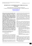
1
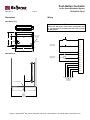
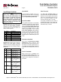
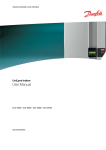
Push Button Controller
for the Smart Distributed System
PBC-5030-1
TECHNICAL DATA
0104
Description
The Holjeron Push Button Controller
for SDS provides a convenient method
to connect push button stations in a
Smart Distributed System installation.
The Push Button Controller provides
six (6) inputs and four (4) outputs. Inputs and outputs use bus power for
their voltage source.
The Push Button Controller can be
purchased as a stand-alone card, or
with different brackets, depending on
the application. Holjeron can also design brackets to meet specific packaging requirements.
Warranty/Remedy
Seller warrants its products to be
free from defects in design, material
and workmanship under normal use
and service. Seller will repair or replace without charge any such products it finds to be so defective on its
return to Seller within 18 months after date of shipment by Seller. The
foregoing is in lieu of all other expressed or implied warranties (except title), including those of merchantability and fitness for a particular purpose. The foregoing is
also purchaser’s sole remedy and is
in lieu of all other guarantees, obligations, or liabilities or any consequences incidental, or punitive damages attributable to negligence or
strict liability, all by way of example.
While Holjeron provides application
assistance, personally and through
our literature, it is up to the customer
to determine the suitability of the
product in the application.
All information contained herein, including illustrations, specifications
and dimensions, is believed to be reliable as of the date of publication,
but is subject to change without notice.
Specifications
Part Number
DeviceNet
Inputs
Outputs
Environmental
Physical
Push Button Controller Only
PBC with Mini Bulkhead Bracket
PBC with 22.5 mm Bracket
PBC with 30.5 mm Bracket
Voltage Range
Current Consumption
Data Rates
Type
Number
Voltage Range
Maximum Current
Type
Number
Voltage Range
Maximum Current
Temperature
Storage
Operating
Humidity
Vibration
Shock
Dimensions (card only)
Weight
Mounting
SDS300-05
SDS300-22
SDS300-30
Terminations
Indication
Status
Activity
PBC-SDS300
PBC-SDS300-05
PBC-SDS300-22
PBC-SDS300-30
11-25 VDC
60 mA plus inputs and outputs
125, 250, 500 and 1000 kbps
Open collector
Six (6)
11-25 VDC (bus voltage)
20 mA per input
Current Sourcing
Four (4)
11-25 VDC (bus voltage)
200 mA
-30° to 70° C (-22° to 158° F)
0° to 60° C (32° to 140° F)
5-95% RH, non-condensing
2G at 10 to 500 Hz
10G
2.79" H x 2.00" W x 0.38" W
6 oz
Mini bulkhead bracket
22 mm button mount bracket
30 mm button mount bracket
Pluggable terminal block, 17 pos.
Red/Green
Green
Holjeron • 25599 SW 95th Ave. Suite E • Wilsonville, OR 97070 • 503.582.0820 • Fax 503.582.9166 • www.holjeron.com
Push Button Controller
for the Smart Distributed System
PBC-5030-1
TECHNICAL DATA
Page 2
Dimensions
Wiring
PBC-SDS300 Only
17
Note
1
17 Pos Pluggable Terminal
Wire Entry Opposite Side
Outputs use SDS power. Lamp current consumption must
be considered when calculating the total power used by
an SDS network.
0.50
2.00
No Components Reserved for
Mounting
Component
Side
LEDs
1.34
In 0
0.38
Ø 0.156
In 1
0.38
In 2
Input Wiring
(Typical of 6)
0.156
2.44
In 3
In 4
0.156
0.156
In 5
2.75
V+
Out 0
PBC-SDS300-05
Out 1
Output Wiring
(Typical of 4)
Out 2
Out 3
V+
BUS V+
BUS +
SHIELD
BUS BUS V-
1.00
DeviceNet
Connector
Hole for Bulkhead
3.50 in.
Minimum
Enclosure
Width
Holjeron • 25599 SW 95th Ave. Suite E • Wilsonville, OR 97070 • 503.582.0820 • Fax 503.582.9166 • www.holjeron.com
Push Button Controller
for the Smart Distributed System
PBC-5030-1
Page 3
Configuration Tools
Quick Start
A Push Button Controller can be configured using several tools. The information
below summarizes the configuration tools
available and hardware requirements for
each tool.
The following steps are the minimum
steps to configure Push Button Controller. Default values are shown in
bold typeface.
Holjeron Device Manager for SDS
Requires an HSIM Portable (RS-232 to
CAN converter) that connects to the serial
port of a personal computer. The bus or
the HSIM Portable must have power.
TECHNICAL DATA
Set Device Address
Using one of the tools described above,
change the device address from the default. All units are shipped from the factory as address 126.
Note
Set the address before attaching any
component to a complete bus. This
will help prevent duplicate addresses
on a bus.
Honeywell hand-held activator
The Honeywell activator may not supply
enough power by itself. The SDS bus
might require external power to be applied.
Think & Do Software
Requires a Honeywell PC Interface Card
with separate bus power. Follow the instructions for installing the SDS Driver in
I/O View.
Tag Name
Tag Name (attribute 56) is a 32character string that the user can enter to
describe the functionality and/or location
of each channel of the Push Button Controller.
Holjeron • 25599 SW 95th Ave. Suite E • Wilsonville, OR 97070 • 503.582.0820 • Fax 503.582.9166 • www.holjeron.com
Push Button Controller
for the Smart Distributed System
TECHNICAL DATA
PBC-5030-1
Page 4
Input/Output Variables
Input NO/NC
Flash Time (0-3)
The Push Button Controller can be configured to invert the state of an incoming
input point by turning on the corresponding bit in Input NO/NC (attribute 60).
The Flash Time (attributes 64-67) set
the rate at which the output will alternate
between on and off states when both the
output and corresponding flash bits are
set to 1. The time is entered in 10 millisecond increments (100 = 1 second).
Input Event Mode
For example, if attribute 64 has a value of
50 when bits 0 and 4 in the output variable are both enabled, output 0 will alternate states every ½ second.
Note
When using a packaged control system, such as Think & Do Software, it is
not necessary to explicitly read input
and output variables. The SDS I/O
Driver and Interface Card perform this
function. All that is required is to map
inputs and outputs as described in the
software user manual.
Attribute 18 functions as the input attribute for the Push Button Controller.
Whenever an event is generated that reports the state of inputs, the data in attribute 18 will be passed.
Bit
0
1
2
3
4
5
6
7
Name
Input 0
Input 1
Input 2
Input 3
Input 4
Input 5
Reserved
Reserved
Description
State of physical input 0
State of physical input 1
State of physical input 2
State of physical input 3
State of physical input 4
State of physical input 5
Alternate Action Mask
Attribute 34 functions as the output attribute for the Push Button Controller.
Whenever the host controller changes the
state of an output it is inherently writing to
attribute 34.
Bit
0
Name
Output 0
1
Output 1
2
Output 2
3
Output 3
4
Flash 0
5
Flash 1
6
Flash 2
7
Flash 3
Most systems will require a Push Button
Controller to generate an event whenever
one or more inputs change state. This requires the Unsolicit Mode (attribute 6)
be enabled by setting its value to 1. Other
options are to disable change of value
events (Unsolicit Mode = 0) or use the
Cyclic Timer (Attribute 10) by setting it
to some non-zero value. The Cyclic Timer
will transmit the input variable on an interval equal to the value in the Cyclic Timer
attribute times 10 milliseconds (0.01 seconds).
Description
Controls the state of
physical output 0
Controls the state of
physical output 1
Controls the state of
physical output 2
Controls the state of
physical output 3
When enabled concurrently with Output 0
causes Output 0 to
flash.
When enabled concurrently with Output 1
causes Output 1 to
flash.
When enabled concurrently with Output 2
causes Output 2 to
flash.
When enabled concurrently with Output 3
causes Output 3 to
flash.
When a bit in the Alternate Action Mask
(attribute 63) is set to a value of 1 and
the physical input with the same bit number turns on, the value reported in the input variable will change state and remain
in that state until the physical input is cycled.
Push-To-Test Mask
When a bit is set to 1 (enabled) in the
Push-To-Test Mask (attribute 70), and
the input with same bit number is on, all
outputs will be energized to test lamps in
the system.
Holjeron • 25599 SW 95th Ave. Suite E • Wilsonville, OR 97070 • 503.582.0820 • Fax 503.582.9166 • www.holjeron.com
Push Button Controller
for the Smart Distributed System
TECHNICAL DATA
PBC-5030-1
Page 5
Diagnostics
CHKSUM
FBULB
A ROM checksum error is generated on
power up if there is a memory error test.
The Push Button Controller contains circuitry that determines whether a lamp is
missing or burnt out. Setting each bit in
the Lamp Test Mask (attribute 68) that
corresponds with outputs that are driving
lamps enables the lamp test for that output.
The Diagnostic Register (attribute 9) is
two bytes and contains the minimum diagnostics required for the Smart Distributed System, plus additional diagnostics
specific to the Push Button Controller.
Diagnostic Register Bit Definitions Byte 0
Bit
0
1
Name
CHKSUM
WDOG
2
BUSOFF
3
4
5
6
7
DEVERR
NODE
RSVD
RSVD
EPRM
Description
ROM checksum error
Output watchdog timer
expired
Off us communications
error
Fatal component error
Missing node detected
Reserved
Reserved
EEPROM error detected
Diagnostic Register Bit Definitions Byte 1
Bit
0
1
Name
RSVD
FBULB
2
3
4
5
6
7
RSVD
RSVD
RSVD
RSVD
RSVD
RSVD
Description
Reserved
Failed Bulb Test. The
specific bulb is identified in attribute 69.
Reserved
Reserved
Reserved
Reserved
Reserved
Reserved
SDS host controllers are equipped to receive a diagnostic event, then automatically obtain the information from the Diagnostic Register (attribute 9). Consult
the documentation for the host controller
being used to determine how errors are
handled.
WDOG
The WDOG diagnostic occurs whenever
the Output Watchdog Timer (attribute
50) times out.
The Output Watchdog Timer is reset
whenever the Push Button Controller receives a message over SDS. If a message is not received in the time entered
any point configured as an output will be
set to the state for that bit in the Default
Output (attribute 51).
When the lamp test is enabled for an output and the lamp is missing or burnt out
the Failed Lamp Register (attribute 69)
will contain a value of 1 in the bit location
that corresponds with that output.
The Output Watchdog Timer is entered in
increments of 10 milliseconds (0.01 seconds). For example, a value of 100
equals 1 second.
Device Monitoring
In addition to diagnostic events, there are
two attributes that can be used to monitor
a node for maintenance purposes.
BUSOFF
The CAN controller on the Push Button
Controller counts error messages. Every
error message increments a counter by 8,
every good message decrements the
counter by 1. If the counter reaches 128
then the module will go BUSOFF. The
microcontroller on the PBC will attempt to
reset if a BUSOFF occurs. If the PBC is
unable to reset itself, it will need to be reset by the host controller.
Reset Count
The Reset Count (attribute 53) is the
number of times the microprocessor on
the Push Button Controller has been reset, including power cycles and resets
from fault conditions. A unit on a bus that
has a higher reset count than other nodes
on the same bus may be experiencing
communications difficulties.
DEVERR
The DEVERR diagnostic bit will be set if a
fatal error is detected within the component.
NODE
Service Time
Service Time (attribute 54) is the number of hours the Push Button Controller
has been in operation.
The host controller will report the node is
missing using the NODE bit.
EPRM
The EPRM error will occur when the microprocessor on the Push Button Controller is unable to read or write EEPROM.
Holjeron • 25599 SW 95th Ave. Suite E • Wilsonville, OR 97070 • 503.582.0820 • Fax 503.582.9166 • www.holjeron.com
Push Button Controller
for the Smart Distributed System
PBC-5030-1
Attributes
Actions
Events
TECHNICAL DATA
Page 6
R/W
Data Type
Size
R
R
R
R
R
W
R
R
W
W
R
R
R
R
W
R
W
W
W
R
R
R
W
W
W
W
W
W
W
W
R
W
Unsigned
Unsigned
Unsigned
Unsigned
Unsigned
Boolean
Character
Unsigned
Unsigned
Unsigned
Unsigned
Character
Character
Character
Character
Boolean
Boolean
Unsigned
Boolean
Unsigned
Unsigned
Unsigned
Character
Boolean
Boolean
Unsigned
Unsigned
Unsigned
Unsigned
Boolean
Boolean
Boolean
Byte
Byte
Byte
Word
Byte
Undef
Undef
Byte
Byte
Word
Long
Undef
Undef
Undef
Undef
Undef
Undef
Word
Undef
Word
Word
Byte
Undef
Undef
Undef
Byte
Byte
Byte
Byte
Undef
Undef
Undef
Count
ID
Description
0
1
2
3
4
6
7
8
9
10
11
12
13
14
15
18
34
50
51
53
54
55
56
60
63
64
65
66
67
68
69
70
Network Data Descriptor
Baud Rate
Object Model
Vendor Id
Logical Address
Unsolicit Mode
Software Version
Diagnostic Counter
Diagnostic Register
Cyclic Timer
Serial Number
Date Code
Catalog Listing
Vendor
Description
Input Variable
Output Variable
Output Watchdog Timer
Default Output
Reset Count
Service Time (hours)
Manufacturing Codes
Tag Name
Input NO/NC
Alternate Action Mask
Flash Time – Output 0
Flash Time – Output 1
Flash Time – Output 2
Flash Time – Output 3
Lamp Test Mask
Failed Lamp Register
Push-To-Test Mask
ID
Description
Request Data
Response Data
0
1
2
6
8
10
51
52
53
57
60
NOOP
Change Address
Self Test
Clear All Errors
Enroll Logical Device
Change Baud Rate
Force State
Unforce States
Read Attribute Descriptor
Password
Reset Factory Defaults
--New logical address
------New baud rate (0…4)
Input variable value
---
Attribute Id
Password
Attribute ID, Attribute Descriptor
ID
Description
Event Data
Diagnostic Event
End-Of-Timer
Change of Value
NOOP
Number of enabled diagnostic bits in attribute 9
Attribute, Input variable
Attribute, Input variable
---
0
3
6
7
6
1
5
1
1
1
12
1
2
1
1
4
32
32
32
6
8
1
8
1
1
1
32
6
6
1
1
1
1
4
4
6
Default
0 [autobaud]
9 [Holjeron]
125
1 [enabled]
0 [disabled]
PBC-SDS300
Holjeron
Push Button Controller
0 [disabled]
0
0 (N.O.)
0
50
50
50
50
0
0
----Vendor Id, Serial Number
Holjeron • 25599 SW 95th Ave. Suite E • Wilsonville, OR 97070 • 503.582.0820 • Fax 503.582.9166 • www.holjeron.com