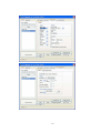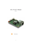
1
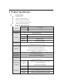
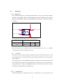
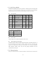
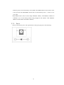
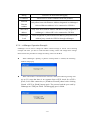
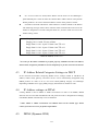
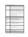
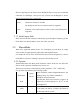
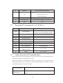
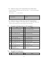
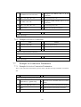
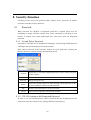
CIE-H10 User’s Manual
Version 1.5
Sollae Systems Inc.
To all residents of the European Union
Important environmental information about this product
This symbol on this unit or the package indicates that disposal of this unit after its
lifecycle could harm the environment. Do not dispose of the unit as unsorted municipal
waste; it should be brought to a specialized company for recycling. It is your responsibility to
return this unit to your local recycling service. Respect your local environmental regulation. If in
doubt, contact your local waste disposal authorities.
-2-
- Table of Contents –
1.
INTRODUCTION ........................................................................................................... - 6 -
1.1.
2.
INTRODUCTION ...............................................................................................................- 6 PRODUCT SPECIFICATION ....................................................................................... - 7 -
2.1.
COMPONENTS..................................................................................................................- 7 -
2.2.
PRODUCT SPECIFICATION ................................................................................................- 7 -
2.3.
INTERFACE ......................................................................................................................- 8 -
2.3.1.
Input Port ...................................................................................................................... - 8 -
2.3.2.
Output Port ................................................................................................................... - 8 -
2.3.3.
RS232 Port (DB9M).................................................................................................... - 10 -
2.3.4.
Ethernet Interface........................................................................................................ - 10 -
2.3.5.
Power .......................................................................................................................... - 11 -
2.3.6.
System LED ................................................................................................................. - 12 -
2.3.7.
ISP Switch ................................................................................................................... - 12 -
3.
TEST OPERATION ...................................................................................................... - 13 -
3.1.
INSTALLATION PROCEDURE ...........................................................................................- 13 -
3.1.1.
Communication Environment Confirm........................................................................ - 13 -
3.1.2.
Network Connection.................................................................................................... - 13 -
3.1.3.
Environmental Factor Setup........................................................................................ - 13 -
3.1.4.
Test Operation............................................................................................................. - 13 -
3.2.
TEST OPERATION ...........................................................................................................- 14 -
3.2.1.
PC IP Address change................................................................................................. - 14 -
3.2.2.
CIE-H10 Installation................................................................................................... - 14 -
3.2.3.
CIE-H10 Setup ............................................................................................................ - 14 -
3.2.4.
Modbus/TCP Test ........................................................................................................ - 17 -
3.2.5.
Test using Web Browser (HTTP) ................................................................................. - 18 -
4.
IP ADDRESS AND SETTING VALUES...................................................................... - 20 -
4.1.
IP ADDRESS AND SETTING VALUES .................................................................................- 20 -
4.2.
SETTINGS BY EZMANAGER ............................................................................................- 20 -
4.2.1.
ezManager................................................................................................................... - 20 -
4.2.2.
ezManager Buttons...................................................................................................... - 21 -
4.2.3.
ezManager Settings ..................................................................................................... - 22 -
4.2.4.
ezManager Operation Example................................................................................... - 23 -
4.3.
IP ADDRESS RELATED CATEGORIES SETTINGS VIA DHCP ...........................................- 24 -
-3-
4.4.
IP ADDRESS SETTINGS VIA PPPOE................................................................................- 24 -
4.5.
DDNS (DYNAMIC DNS)...............................................................................................- 24 -
5.
I/O INTERFACE........................................................................................................... - 26 -
5.1.
MODBUS/TCP ...............................................................................................................- 26 -
5.1.1.
Modbus/TCP Setting Values ........................................................................................ - 27 -
5.1.2.
Standard Modbus/TCP ................................................................................................ - 28 -
5.1.3.
Modbus/TCP Master Mode ......................................................................................... - 28 -
5.1.4.
TCP Connection Mode ................................................................................................ - 28 -
5.1.5.
Initial Output Value ..................................................................................................... - 29 -
5.2.
MACRO MODE ..............................................................................................................- 29 -
5.2.1.
Operator...................................................................................................................... - 29 -
5.2.2.
Operand ...................................................................................................................... - 30 -
5.2.3.
Example of Equation ................................................................................................... - 30 -
5.3.
MONITOR AND CONTROL USING WEB (HTTP)...............................................................- 31 -
5.3.1.
Connect to Web............................................................................................................ - 31 -
5.3.2.
Read/Write Using Web................................................................................................. - 32 -
6.
SERIAL INTERFACE .................................................................................................. - 33 -
6.1.
SERIAL COMMUNICATION MODE ....................................................................................- 33 -
6.2.
T2S MODE ....................................................................................................................- 34 -
6.2.1.
Connection .................................................................................................................. - 34 -
6.2.2.
Serial Data before TCP Connection............................................................................ - 34 -
6.2.3.
Data Communication .................................................................................................. - 34 -
6.2.4.
Connection Termination.............................................................................................. - 35 -
6.3.
COD .............................................................................................................................- 36 -
6.3.1.
Serial Data before Connection.................................................................................... - 36 -
6.3.2.
Data Communication .................................................................................................. - 36 -
6.3.3.
Connection Termination.............................................................................................. - 37 -
6.4.
ATC ..............................................................................................................................- 38 -
6.5.
U2S...............................................................................................................................- 39 -
7.
ATC MODE ................................................................................................................... - 40 -
7.1.
OUTLINE .......................................................................................................................- 40 -
7.1.1.
AT Command Form ..................................................................................................... - 40 -
7.2.
BASIC AT COMMAND (EX: ATA, ATD ETC)...................................................................- 40 -
7.3.
EXPANDED AT COMMANDS (EX: AT+PLIP ETC.) ..........................................................- 41 -
-4-
7.4.
ONLINE STATUS AND AT COMMAND STATUS .................................................................- 41 -
7.4.1.
Method to change to AT Command Status from Online Status .................................... - 42 -
7.4.2.
Method to change to Online Status from AT Command Status .................................... - 42 -
7.5.
EXAMPLE FOR SETTINGS DONE BY AT COMMANDS .......................................................- 42 -
7.6.
EXAMPLE FOR CONNECTION .........................................................................................- 42 -
7.6.1.
Example for Active Connection................................................................................... - 42 -
7.6.2.
Example for Passive Connection................................................................................. - 43 -
7.7.
EXAMPLE FOR CONNECTION TERMINATION ..................................................................- 43 -
7.7.1.
Example for Active Connection Termination............................................................... - 43 -
7.7.2.
Example for Passive Connection Termination ............................................................ - 44 -
8.
SECURITY FUNCTION .............................................................................................. - 45 -
8.1.
PASSWORD ....................................................................................................................- 45 -
8.1.1.
Set and Delete Password............................................................................................. - 45 -
8.1.2.
CIE-H10 settings with Designated Password ............................................................. - 45 -
8.1.3.
Connect via Web Browser ........................................................................................... - 46 -
8.1.4.
When Password is Lost ............................................................................................... - 46 -
8.2.
CONNECTION RESTRICTION FUNCTION .........................................................................- 47 -
8.2.1.
Allowed Ethernet Address ........................................................................................... - 47 -
8.2.2.
Allowed IP Address ..................................................................................................... - 47 -
8.2.3.
ezManager Lock .......................................................................................................... - 48 -
9.
DEBUGGING ................................................................................................................ - 49 -
9.1.
TELNET .........................................................................................................................- 49 -
9.1.1.
Telnet Login................................................................................................................. - 49 -
9.1.2.
Commands................................................................................................................... - 49 -
9.2.
STATUS OF EZMANGER ..................................................................................................- 50 -
9.3.
REMOTE DEBUGGING ....................................................................................................- 50 -
10. TECHNICAL SUPPORT/GUARANTEE PERIOD/PRECAUTIONS..................... - 52 10.1.
TECHNICAL SUPPORT ....................................................................................................- 52 -
10.2.
GUARANTEE..................................................................................................................- 52 -
10.2.1.
Refund ..................................................................................................................... - 52 -
10.2.2.
Compensated A/S .................................................................................................... - 52 -
10.2.3.
Non-compensated A/S ............................................................................................. - 52 -
10.3.
11.
PRECAUTIONS ...............................................................................................................- 52 REVISION HISTORY .................................................................................................. - 54 -
-5-
1.
Introduction
1.1.
Introduction
The need for the data communication system via internet is rapidly increasing due to the
development of internet through out the world. In order to send and receive data via internet,
TCP/IP protocol must be used. Any machines that need an internet connection must
implement TCP/IP protocol. In order for any device to implement TCP/IP protocol, the
machine must either be able to implement TCP/IP protocol by itself, have an open TCP/IP
source implanted, or must use an OS that is capable of implementing the protocol. However,
the above options require a great deal of time, cost, and effort to make it work.
CIE-H10 uses MODBUS/TCP and HTTP to provide users with ability to control and
monitor remote digital I/O controllers. Therefore, with CIE-H10, remote I/O devices can
easily be controlled and monitored at the same time. Also, CIE-H10 provides the Macro
functions to automatically change the output value via output port based on the input value
from the input port.
Not only that CIE-H10 can control and monitor digital I/O controllers, it also provides with
functions that can covert the serial data to TCP/IP data and vice versa. Therefore, one CIEH10 can perform numerous functions at the same time.
Along with its strong TCP/IP/UDP functions, CIE-H10 also provides DHCP and PPPoE
functions to be used in cable and xDSL networks. And it has DDNS(Dynamic DNS)
function, so it can be used more easily in the internet.
It is also equipped with online debugging functions that will allow the users to quickly
respond to the problems that might occur during the installation.
-6-
2. Product Specification
2.1.
Components
z
CIE-H10 body
z
5V Power Adapter (Option)
z
RS232C Cable for PC (Option)
z
Cross-over Ethernet cable (Option)
z
Adapter for DIN rail (Option)
2.2.
Product Specification
Power
Input Power
5V (±10%)
Used Current
510mA typical
Product Size
153mm x 126mm x 32mm
Weight
Approximately 530g
Interface
Input Port
8 Port Photo coupler
Output Port
8 Port Relay
Serial
Dsub 9Pin male
Network
10/100 Base-T (RJ45)
Ethernet 10/100 M bit auto-sense
Network
Auto MDI/MDIX(Cable Auto-sensing)
TCP, UDP, IP, ICMP, ARP, DHCP, PPPoE
DNS lookup Dynamic DNS(DDNS)
Protocol
Telnet COM Port Control Option(RFC2217)
MODBUS/TCP, HTTP
Diagnose
Online Debugging Function
Environment
Follows Europe RoHS Regulation
CE: F690501/SP-EMC000976
Certification
Communicati
on Mode
Programs
MIC: SLS-CIE-H10
Input/Output
Modbus/TCP – Slave/Master, Passive/Active
Web Browser(HTTP)
Port
Macro Movement(Macro)
Serial Port
TCP Server/Client, AT emulation, UDP
ezManager
Set up program via LAN
Ezterm
Socket communication program for testing
hotflash
Firmware download program using TFTP
-7-
2.3.
Interface
2.3.1. Input Port
Since CIE-H10 input port is isolated by photocouplers, users may connect the machine
regardless of its polarity. The circuit of the input port is shown in the below. It is the part
where the [EXTERNAL INPUT1] and [EXTERNAL INPUT2] are interfaced with the
user device.
10K
VCC_33
EXTERNAL INPUT1
TO_PROCESSOR
EXTERNAL INPUT2
The specifications of the input port are as the following:
Max. Input Voltage
DC24V
VIH
Min. 1.8V
H
1
VIL
Max. 1.2V
L
0
Since the input port is interfaced with a 5mm terminal block, use a (-) shaped
screwdriver to connect it with the user device.
z
Valid Time
CIE-H10 will only recognize input port signals that last for the [Valid Time] set by the
user. If the signal is not maintained during the designated [Valid Time], the input signal
will be ignored.
The [Valid Time] is used for Modbus/TCP, Macro, HTTP, and other functions provided
by CIE-H10. The unit used for the [Valid Time] is 1ms. However, since the accuracy is
only guaranteed in 10ms, the designated values will round down in units of 10ms
according to the designated values by the users.
2.3.2. Output Port
CIE-H10 output port is interfaced via relay as shown below. It is the part where the
-8-
[EXTERNAL OUTPUT1] and [EXTERNAL OUTPUT2] are interfaced with the user
device.
EXTERNAL OUTPUT1
2
1
5
VCC_5V
FROM_PROCESSOR
3
EXTERNAL OUTPUT2
RELAY SPST
The output port will perform the following actions
Value
Relay contact
0
OFF
1
ON
The allowed electrical current based on voltage conditions of the output port are as the
following:
Voltage
Condition
Allowed
electrical
current
DC28V
5A
AC125V
10A
AC250V
5A
Since the output port is interfaced with a 5mm terminal block, use a (-) shaped
screwdriver to connect it with the user device.
z
Delay
CIE-H10 will send output value to the output port after waiting for [Delay] ms.
In order to do so, the signal value must last for [Delay] seconds. If the output value does
not last for the [Delay] seconds, CIE-H10 will not send that signal to the output port.
If the [Delay] value is set as 0, CIE-H10 will send the output value to the output port
immediately.
The [Delay] is used for Modbus/TCP, Macro, HTTP, and other functions provided by
CIE-H10. The unit used for the [Delay] is 1ms. However, since the accuracy is only
guaranteed in 10ms, the designated values will round down in units of 10ms according
to the designated values by the users.
-9-
2.3.3. RS232 Port (DB9M)
CIE-H10 has an RS232 port for user serial device. CIE-H10 converts serial data from
user device to TCP/IP and transmits to Ethernet port. And CIE-H10 convert TCP/IP data
from Ethernet port to user serial device and it transmits raw data to user device.
z
z
z
Pin Assignment
number name description
level
Dir.
Etc.
1
DCD
Data Carrier Detect
RS232
Input
option
2
RXD
Receive Data
RS232
Input
required
3
TXD
Transmit Data
RS232
Output required
4
DTR
Data Terminal Ready RS232
5
GND Ground
Ground -
required
6
DSR
Data Set Ready
RS232
Input
option
7
RTS
Request To Send
RS232
Output option
8
CTS
Clear To Send
RS232
Input
option
9
RI
Ring Indicator
RS232
Input
option
Output option
Data bits, Parity, and Stop bit
Item
Configurable Value
Data bit
8, 7, 6, 5
Parity
None, Even, Odd
Stop bit
1, 1.5, 2
Flow Control
CIE-H10 support None and RTS/CTS Hardware Flow Control.
z
Telnet COM Port Control Option
CIE-H10 has Telnet COM Port Control Option function that is specified by RFC2217. If
the Telnet COM Port Control Option is enabled, CIE-H10 sends the CTS, DSR control
signal to the communication counter part, and CIE-H10 sets its serial port items(RTS,
DTR, Baudrate, databits, parity, stop bit) after getting information from the
communication counter part.
2.3.4. Ethernet Interface
Since part of CIE-H10 network is composed of Ethernet, UTP cable may be connected. The
- 10 -
Ethernet portion will automatically sense 10Mbit and 100Mbit Ethernet and connect itself.
It also provides auto MDI/MDIX function that can automatically sense 1:1 cable or cross
over cable.
Each Ethernet device has its own unique hardware address. The hardware address of
CIE-H10 is set in the factory before being shipped to the market. (The hardware
address is also known as the MAC address.)
2.3.5. Power
DC5V is used for the power. The specifications of the power plug are as the following:
- 11 -
2.3.6. System LED
CIE-H10 has numerous lamps to show the current system status.
Each lamp shows the following status:
Name
Color
LED Status
Details
PWR
Red
On
When the power is on
Flicker with
When the IP address is set as a fixed IP
1s interval
address, or when the dynamic IP is allocated
STS
Yellow
Flicker for 4
times within
When the dynamic IP address is not allocated
1s
Green
LINK
Off
ISP mode
On
When connected to 100 M network
Flicker
On
Red
Flicker
When there is data in LAN while being
connected to 100 M network
When connected to 10 M network
When there is data in LAN while being
connected to 10 M network
RXD
Yellow
Flicker
When receiving Ethernet packet
TXD
Green
Flicker
When sending Ethernet packet
DI
Yellow
On
Input ON(High) signal to input port
DO
Green
On
Output ON signal from output port relay
2.3.7. ISP Switch
There is an ISP switch located on the side of the product. It is a switch that will allow
CIE-H10 to perform in ISP mode. If the switch is pressed more than 100ms or the power
is turned on as the switch is pressed, CIE-H10 will be activated in ISP mode.
- 12 -
3. Test Operation
3.1.
Installation procedure
CIE-H10 can be installed with the following procedure.
Large category
1.
Communication
Environment Confirm
Small category
IP address environment
Confirm
Modbus/TCP, HTTP, Macro
categories
Serial port value
Application program
2.
Confirm
Network Connection
method
3.
Details
Check for LINK LED light
Setup Method
Network Setup utility, ezManager
4.
Confirm
Check with ezManager or Web
Test Operation
5. Operation
method
browser(HTTP)
Environmental factor setup
3.1.1. Communication Environment Confirm
Check IP address, network environment, serial port value, protocols used in controlling
digital I/O devices and other application programs before installing CIE-H10.
3.1.2. Network Connection
After connecting CIE-H10 to the power, directly connect it with PC’s Ethernet port or
connect it with the network (hub) that the PC is connected to. When the LINK LED is on,
the network is established.
However, since CIE-H10 is only physically connected, IP related values must be designated
to perform ping test and IP communication.
3.1.3. Environmental Factor Setup
When network connection is established, ezManager program will be used to perform setup
via LAN.
3.1.4. Test Operation
With ezManager provided by Sollae Systems or with web browser, the test operation
may be performed. For more details, please refer to 3.2 test operation.
- 13 -
3.2.
Test operation
The test operation may be performed according to the following procedure. The test
operation suggested in this manual is based on the assumption that IP of PC is set as 10.1.0.2.
3.2.1. PC IP Address change
Change IP address of PC as the following:
IP address
10.1.0.2
Sub net mask
255.0.0.0
Gateway IP address
-
3.2.2. CIE-H10 Installation
Connect LAN cable directly to the LAN port of CIE-H10 or connect it to the hub where PC
is connected to. Also, provide power to CIE-H10 using CIE-H10 power adapter. When the
power is connected, the LINK LED will light up when a proper connection to the LAN cable
is established.
3.2.3. CIE-H10 Setup
Using ezManager, change the settings of CIE-H10. Start ezManager and click [Search
ezTCP] button on the ezManager window. Then, ezManager will search for every ezTCP on
the local network.
When there is no result, click [WinXP Firewall] button on the ezManager window to check
for firewall setting value. If there is a firewall, the program cannot perform the search.
When CIE-H10 is found, the MAC address of CIE-H10 will be shown on the [Search
Results] window. (The MAC address is also written on the bottom of the product case.)
Select the MAC address and set its value as same as the values shown in the photos below.
Then, click [Save] to save the setting values.
- 14 -
- 15 -
- 16 -
3.2.4. Modbus/TCP Test
It is a test of CIE-H10 to perform control and monitor functions using Modbus/TCP.
This test should be performed with Modbus/TCP program provided by Sollae Systems.
- 17 -
After having settings as same as the settings shown
above, click on the [CIE-H10 TEST] button. A new
window on the ezManager will pop up.
z
Click [Connect] button to connect to CIEH10 by TCP connection
z
In order to check for the [Digital Output]
port, click on Do0 to Do7 buttons of the
[Digital Output] to check for output values
being sent.
z
When the [Start Write] button is clicked,
previously designated values will be sent to
the [Digital Output] port periodically.
z
In order to check for the [Digital Input] port,
click [Start Read] button to read values off of
the
[Digital
Input]
port
every
period
designated by the [Interval] value.
3.2.5. Test using Web Browser (HTTP)
Start the web browser as shown below and write http:// and IP address in the address
window to connect to the CIE-H10 web browser. It will allow users to monitor and
control CIE-H10.
Click on the [Read] button to read input/output values.
Designate output values on the CIE-H10’s output port (DO0 – DO7) and click [Write]
button to apply setting values to the CIE-H10’s output port. Then, the CIE-H10’s input
port value will be read as well.
- 18 -
- 19 -
4. IP Address and Setting Values
4.1.
IP address and setting values
In order to perform TCP/IP communication, the settings related to the IP address must be
designated.
IP address and serial port related settings may be designated by the network set up utility
provided by Sollae Systems, ezManager.
4.2.
Settings by ezManager
4.2.1. ezManager
The basic settings of CIE-H10 (IP address settings and serial port settings) can be designated
by an application utility for Windows, ezManager. ezManager can be operated in Windows
platform (Windows 98, 98SE, 2000 pro, ME, XP pro/home) but may malfunction in older
OS versions. The following window is the window that pops up when the user starts
ezManager for the first time.
ezManager communicates with CIE-H10 via UDP broadcast. The port used during the
communication is 50005 and the UDP port used during the debugging process is 50006.
If the firewall functions are being used, the firewall functions for the 50005 and 50006
port must be turned off.
- 20 -
4.2.2. ezManager Buttons
Search for all CIE-H10s series connected to the local network. The search results
Search
ezTCP
will be shown on the [Search Result] box. Using mouse or cursor, the desired
products may be selected. The values shown on the box are MAC addresses of each
ezTCP, and the selected ezTCP’s setting values will be shown on the right. (The
MAC address of CIE-H10 is written on the bottom of the product)
Input 6 digit number written on the CIE-H10 product sticker to the MAC
ADDRESS input box or Input CIE-H10’s IP address in the IP address category on
Read
the REMOTE tab. This will allow the user to read setting values for a specific CIEH10. When there are too many ezTCPs connected to the network and it is hard to
find a desired ezTCP from the LIST box, this button may be conveniently used.
After changing the settings, save the changes to ezTCP. CIE-H10 will
Save
automatically reset after the save. Therefore, pressing this button may cause system
shutdown during normal use.
CIE-H10 provides user authentication function in order to prevent other people
from changing its settings. The authentication process is done using a password and
Change
PWD
this button will allow users to change the password. If the password for the
ezManager is already designated, the program will ask the user to input password
as the button is clicked.
The designated password will also be used when connected to the web (HTTP).
The ID is ‘admin’.
User can check the status values of CIE-H10 during its operation. When the button
Status
is clicked, a new window will pop up and show operation time, current IP address,
data amount via serial port and other information. Clicking each devices of the
[Search List] will also yield the same information.
This will be used to read debugging messages from CIE-H10. In order to
Debug
use this function, activate [Debug] option under [OPTION] tab. When the
Message debugging is over, please deactivate the [Debug] option to minimize
network load.
WinXP
Firewall
Exit
When the PC’s firewall is activated, ezManager may not be operated
properly. By clicking this button, the user can easily check their Windows
firewall status.
Exit ezManager
- 21 -
4.2.3. ezManager Settings
NETWORK
Network
Local IP
Address
CIE-H10’s IP address
Subnet Mask
Gateway IP
Address
DNS IP
Address
Subnet Mast
Gateway’s IP address
Name Server’s IP address
Option
DHCP
Decide whether to receive CIE-H10 IP address via DHCP
PPPoE
Decide whether to receive CIE-H10 IP address via PPPoE
PPPoE ID
& Password
ID and Password that will be used in PPPoE
ARP
ARP Function activation status (Conditionally required for DHCP)
Obtain DNS
If CIE-H10’s IP address is set as a dynamic IP (DHCP or PPPoE), it
server
will automatically receive DNS server address. If this check box is
address
not activated, the IP address designated in the [DNS IP Address] will
automatically
be used as the DNS server address.
DDNS
Service
Set a DDNS service provider.
Provider
CIE-H10 supports only Dyndns(www.dyndns.com).
User ID
The user account which was registered to the service provider
User
The password of user account which was registered to the service
Password
provider
Host Name
The hostname of CIE-H10.
For example: cieh10.dyndns.com
OPTION
Remote
Use IP address to check for device settings in the ezManager’s
Search
REMOTE tab
Telnet
Enable telnet login
- 22 -
Debug
Used for CIE-H10 online debugging
Comments
Allows users to make comments about the products
Allowed
Ethernet
Only allow hosts with Ethernet Address designated in ezManager’s
‘Allowed Ethernet Address’ to be connected to CIE-H10.
Address
Allowed IP
Only allow hosts with IP Address and address range designated in
address
ezManager’s ‘Allowed IP’ to be connected to CIE-H10
ezManager
Hosts designated in [Allowed Ethernet address] and [Allowed IP
Lock
Address] may search the CIE-H10 through ezManager.
4.2.4. ezManager Operation Example
ezManager can be used to change IP address related settings of ezTCP. The Following
example will show you how to read CIE-H10’s setting values and change those settings.
Please follow this procedure to change the setting values of CIE-H10.
z
When ezManager’s [Read], or [Search ezTCP] button is clicked, the following
window will pop up.
z
When ezTCP that is connected to the network is found, the following message will
pop up. If it says that there is no response from ezTCP, check for ezTCP’s
power, LAN cable connection, or [Windows Firewall] status before clicking
[Search ezTCP] or [Read] button again. The protocol and the port used by
ezManager are UDP port 50005. The debugging port is 50006.
- 23 -
z
If 1 ore more ezTCP is found, MAC address will be shown in the ezManager’s
[Search Result] box. Check to make sure that the MAC address shown in the [Search
Result] window is as same as the MAC address written on the product’s sticker.
z
Use PING command in Windows’ DOS window to confirm CIE-H10’s IP address.
The following message will be shown after the PING command when the correct IP
address is designated. If it reads “Request timed out”, check to make sure correct IP
address setting values.
z
C:\>ping 10.1.0.1
Pinging 10.1.0.1 with 32 bytes of data:
Reply from 10.1.0.1: bytes=32 time=1ms TTL=64
Reply from 10.1.0.1: bytes=32 time=1ms TTL=64
Reply from 10.1.0.1: bytes=32 time=1ms TTL=64
Reply from 10.1.0.1: bytes=32 time=1ms TTL=64
<When IP address is 10.1.0.1 >
√ In order for the PING command to perform properly, CIE-H10 and PC’s IP address,
subnet mask, and gateway IP address must be adequately set for the network environment.
4.3.
IP Address Related Categories Settings via DHCP
In the network environment composing DHCP server, settings related to CIE-H10’s IP
address, subnet mask, gateway, and name servers can be automatically designated using
DHCP protocol. In order to do so, user must check [DHCP] category on ezManager.
Depending on DHCP server type, [ARP] category should also be checked as well.
4.4.
IP Address settings via PPPoE
Usually, PPPoE is used in ADSL or VDSL environment. In order to use PPPoE, PPPoE
function must be activated and PPPoE’s ID and password must be designated accordingly.
Like DHCP, PPPoE automatically receives IP address.
√ Some ADSL or VDSL environment uses DHCP based on the modem type. Please
contact your internet service for further information.
4.5.
DDNS (Dynamic DNS)
- 24 -
In internet environment, most host get IP addresses dynamically. In this case, it is very
hard to communicate to the host because the IP address is changed dynamically.
The DDNS function solves this problem. If the CIE-H10 obtains its IP address, it notice
to the service provider. Then the service provider serves DNS service.
So, even though user doesn’t know the CIE-H10’s IP address, user can connect to the
CIE-H10 by the host name (after DNS looking up.)
The
DDNS
service
provider
that
Dyndns(http://www.dyndns.com) currently.
- 25 -
the
CIE-H10
supports
is
only
5. I/O Interface
In CIE-H10, there are 8 input ports interfaced by photo couplers and 8 output ports
interfaced by relays.
These I/O ports can be controlled by three methods: Modbus/TCP, Macro, and Web
(HTTP).
Modbus/TCP protocol is used to communicate with CIE-H10.
Modbus/TCP
When CIE-H10 is in Slave/Passive mode, it operates as a normal
Modbus/TCP device. Master operation may be activated by
other settings. It also can establish TCP Active connection.
It is a mode that allows the users automatically controls output
port’s value based on input port status by setting Macro values
Macro
prior to CIE-H10 operation.
During Macro operation, current status values may be read using
HTTP or Modbus/TCP, but output values may not be controlled.
HTTP may be controlled and monitored using web browser.
Connect to CIE-H10’s IP address via web browser to access
Web(HTTP)
CIE-H10’s control and monitor web page. This webpage shows
current status values. By clicking [Read] button, current
input/output values will be read. Also, change check box values
of output port and click [Write] to change output port value.
5.1.
Modbus/TCP
Since CIE-H10’s input and output port is operated based on Modbus/TCP, CIE-H10 can
be controlled and monitored using Modbus/TCP Manager.
Currently, CIE-H10 only supports Read Multiple (Function Code: 3) and Write Multiple
(Function Code: 16) codes from Modbus/TCP Function Code.
Also, along with Modbus/TCP, CIE-H10’s Active TCP connection, Modbus/TCP master,
and Input Change Notification functions may be used to apply the product to many other
fields.
When the Macro function is activated, users can only read current values using
Modbus/TCP but is not able to output values via output port.
- 26 -
5.1.1. Modbus/TCP Setting Values
Modbus/TCP
Using Modbus/TCP, monitor and control CIE-H10.
Like Modbus/TCP’s standard protocol, CIE-H10 will operate in
Slave mode. When CIE-H10 receives Modbus/TCP query from
Slave
Master, it will process the designated query. However, in order
for CIE-H10 to process the inputted query, the query must match
[Unit ID] and [Input port address]/ [Output port address].
CIE-H10 is operated in master mode. When CIE-H10 connects
with designated address, it will send Read Multiple queries to
previously designated slave’s [Unit ID] and [Input port address]
Master
every [Poll Interval]. The response value will be outputted via
CIE-H10’s output port and master’s [Input Port] value will be
sent via Write Multiple to the slave.
Using this function, remote input port’s value may be sent to
slave’s output port (I/O Tunneling).
Poll Interval
Unit ID
Interval in between CIE-H10’s queries as master (Unit: ms)
Slave mode: CIE-H10의 Unit ID
Master mode: CIE-H10 and remote device Unit ID
Slave mode: CIE-H10 Input port address.
Input port
Master mode: Slave device Input port address.
Address
Input port Address and Output port Address must differ by a
number larger than 8.
Slave mode: Output port address.
Output port
Master mode: Slave Output port address.
Address
Address and Output port Address must differ by a number larger
than 8.
CIE-H10 establishes TCP connection passively.
When remote host connects to previously designated [Port],
Passive
CIE-H10 will allow TCP connection.
In order to communicate using Modbus/TCP, this category must
be selected.
Active
CIE-H10 establishes TCP connection to previously designated IP
address (Peer Address) and Port.
Peer Address
IP address when CIE-H10 performs active connection
Port
Passive connection mode: Local Port number that will receive
- 27 -
connection
Active connection mode: Peer Port number that will establish
TCP connection
As long as there is no query from the Master, standard
Modbus/TCP will not send current status to the remote host.
Input Change
Notification
When CIE-H10’s input port value is changed while this category
is selected, it will send Read Multiple response packet to the
Master without receiving queries from the Master.
This function may be used to quickly send CIE-H10’s Input Port
status.
Initial State
Output port value when CIE-H10 is booted.
5.1.2. Standard Modbus/TCP
Standard Modbus TCP will allow users to use Modbus/TCP Manager to control and
monitor devices that supports Modbus/TCP.
In order to operate in standard Modbus/TCP, select Modbus/TCP mode as [Slave] mode,
change TCP connection as [Passive], and set TCP port number as 502.
Modbus/TCP Mode
Slave
TCP Connection
Passive
TCP Port
502
Also, adequate CIE-H10’s [Unit ID], [Input port address], and [Output port address]
must be selected.
In the case of CIE-H10, [Input port Address] and [Output port Address] must differ by a
number larger than 8.
5.1.3. Modbus/TCP Master Mode
CIE-H10 operates as Modbus/TCP Master and reads input port values off of remote
Modbus/TCP Slave and uses those values in CIE-H10 output port. Then, CIE-H10 sends
its input port value to remote slave device as [Write Multiple] Function Code.
When connecting to Modbus/TCP device, the TCP connection must be in [Active]
setting.
Using this function, CIE-H10 input values can be sent to the remote slave device and
remote slave input port values may be outputted by CIE-H10’s output port.
5.1.4. TCP Connection Mode
Standard Modbus TCP allows user Manger to establish TCP connection to Modbus/TCP
device’s 502 port.
- 28 -
However, depending on the network status, Modbus/TCP device may have to establish
connection to the Manager. In this special case, CIE-H10 can be changed into Active
mode to actively connect to the remote host.
Standard Modbus/TCP
Passive
Remote host connects to CIE-H10
Port number that will receive connection must be designated
CIE-H10 connects to remote host
Active
IP address or host name and port number of the desired host must be
designated
5.1.5. Initial Output Value
Initial value for CIE-H10 output port after booting may be designated. Depending on the
[Initial State] value during the boot, output port will be activated.
5.2.
Macro Mode
When users designated different macros for each output port, CIE-H10 can output
various results via output port using input values and designated macros.
It is a mode that can be used to activate various devices based on signals from various
sensors. .
Check Macro check box in ezManager to activate CIE-H10 macro mode.
5.2.1. Operator
The algorithm used in the Macro mode is Boolean Algebra. In this case, the AND, OR,
NOT are used as operators. Parenthesis may also be used.
The priority of operators is in the following order: parenthesis > NOT > AND > OR.
Each operator is represented by the following symbols.
Parenthesis
Open – (
Close - )
Since calculations within the parenthesis have the
highest priority, they will be calculated first.
Parenthesis may be nested used.
Operand that follows NOT operator is toggled. (If
NOT
/
operand is 0, it will be changed to 1. If it is 1, it will
be changed to 0.)
If Operand values that surrounds AND operator all
AND
*
1, the result value will be 1. If either one of them is
0, the result will be 0 as well.
- 29 -
If Operand values that surrounds AND operator all
OR
+
0, the result value will be 0. If either one of them is
1, the result will be 1
5.2.2. Operand
Operands used in macro mode are each input port. Each input port is designated with i0
~ i7 symbol based on their sequence.
Since capital letters are not recognized, they can also be written as I0 ~I7.
5.2.3. Example of Equation
Let’s assume that the equation settings are the same as the following.
In this case, the equations for two output port are as the following.
Perform OR for i0 and i1.
Do0
i0 + i1
Spaces in between two operands may be
ignored
Perform NOT with value from performing
Do2
i0*/(i1+i7)
OR for i1 and i7. Then, perform AND with
that value and i0
Based on input values from three input ports, the output values are as the following.
- 30 -
Output ports that equations are not applied will be maintained as 0 (OFF).
Input port value
5.3.
Output port value
i0
i1
i7
Do0
Do1
Do2
Do3
Do4
Do5
Do6
Do7
0
0
0
0
0
0
0
0
0
0
0
0
0
1
0
0
0
0
0
0
0
0
0
1
0
1
0
0
0
0
0
0
0
0
1
1
1
0
0
0
0
0
0
0
1
0
0
1
0
1
0
0
0
0
0
1
0
1
1
0
0
0
0
0
0
0
1
1
0
1
0
0
0
0
0
0
0
1
1
1
1
0
0
0
0
0
0
0
Monitor and control using Web (HTTP)
When HTTP check box in ezManager is selected, CIE-H10 input/output port values may
be monitored and controlled using web browser.
5.3.1. Connect to Web
After starting the web browser, type in CIE-H10’s IP address after typing http:// in the
address window to connect to CIE-H10.
If passwords for CIE-H10 are designated, the following window will pop up.
In this case, enter admin for ID and designated password.
This is the initial window when users connect to CIE-H10.
- 31 -
5.3.2. Read/Write Using Web
Current input ports values will be shown in DI0 –D17 check boxes, and output port
values will be shown in DO0 – DO7 check boxes. These values represent CIE-H10
status the moment web browser is connected to CIE-H10 and will not change
automatically as the CIE-H10’s status changes. Therefore, users must click [Read] in
order to read current updated values.
In order to output values designated by the users, designate output values for the desired
output port and click [Write].
If the macro function is activated, users cannot control device’s output port using HTTP.
Users may only read input/output port values.
- 32 -
6. Serial Interface
CIE-H10 provides RS232↔TCP/IP conversion function along with input/output port
monitor and control function. Using this function, existing serial devices may be easily
connected to the TCP/IP network. Also, TCP server, TCP client, AT command emulation,
UDP, and many other devices are supported to provide various applications to the users.
6.1.
Serial communication mode
CIE-H10 has 4 serial communication modes. The following chart is a brief explanation
for each communication mode.
Need for
Communic
ation mode
Protocol
User
Designation of
Device
Environmental
S/W
Factor via Serial
Modificat
Port
Connection
Topology
ion
T2S
TCP
ATC
TCP
COD
TCP
U2S
UDP
Passive
Not
Connection
required
Active/Passiv
e
required
Active
Not
connection
required
No
Not
connection
required
- 33 -
Not possible
1:1
possible
1:1
Not possible
1:1
Not possible
N:M
6.2.
T2S Mode
T2S is the mode that CIE-H10’s serial port operates as a server.
When TCP connection comes through previously designated [Local Port] from remote host,
CIE-H10 will accept TCP connection. When CIE-H10 accepts the connection, TCP
connection is established. After establishing connection, data that comes through serial port
will be sent to the remote host after TCP/IP process, and TCP/IP data that comes from the
remote host will be sent to the serial port after TCP/IP process to establish data
communication.
6.2.1. Connection
When remote host connects to previously designated CIE-H10, user devices that are
connected to CIE-H10 can establish full duplex data communication with remote host.
6.2.2. Serial Data before TCP Connection
Data before TCP connection will be handled based on the [Byte Count] settings. If the
[Byte Count] is 0, the data that comes to CIE-H10’s serial port will not be recognized. If
it is not 0, the serial data before TCP connection will be temporarily saved to be sent to
the host after the connection.
6.2.3. Data Communication
When the TCP connection is established, the data communication in between the host
and the serial device will be established. Then, CIE-H10 will send data according to the
[Guard Time]. In other words, when the data comes through CIE-H10’s serial port, it
- 34 -
will be temporarily saved in the buffer. Then, when there is no incoming data during the
designated [Guard Time], CIE-H10 will send the saved data. If the [Guard Time] is 0,
CIE-H10 will send serial port’s data immediately. The unit used for the [Guard Time] is
10m seconds and its minimum value is 40m seconds. Therefore, the user must set the
number that is greater than 4.
6.2.4. Connection Termination
When the connected host terminates the connection, or there is no data communication
during the designated [Timeout], the TCP connection will be automatically terminated. The
unit used for [Timeout] is 1 second.
- 35 -
6.3.
COD
COD mode is the mode that CIE-H10 operates as a client.
When previously designated [byte count] data comes through the serial port, CIE-H10 will
try to connect to the previously selected [Peer IP Address] host’s TCP port [peer port] via
TCP connection. When the remote host accepts the TCP connection, the TCP connection will
be established. After the connection is established, the data that comes through the serial port
will be sent to the remote host after TCP/IP handling. The TCP/IP data that comes from the
remote host will be sent to the serial port after TCP/IP handling to form data communication.
Remote
RemoteHost
Host
CIE-H10
Listen
Serial Device
DATA “AB”
Request TCP con
DATA “C”
nection
Accept TCP con
nection
connected
Ack
DATA “ABC” (TCP/IP)
DATA “DEF”
DATA “DEF” (TCP/IP)
DATA “GHI” (TCP/IP)
DATA “GHI”
<COD connection sequence – Byte Count: 3>
6.3.1. Serial Data before Connection
Data before TCP connection will be handled based on the [Byte Count] settings. If the
[Byte Count] is 0, the data that comes to CIE-H10’s serial port will not be recognized. If
it is not 0, the serial data before TCP connection will be temporarily saved to be sent to
the host after the connection.
6.3.2. Data Communication
When the TCP connection is established, the data communication in between the host
and the serial device will be established. Then, CIE-H10 will send data according to the
[Guard Time]. In other words, when the data comes through CIE-H10’s serial port, it
will be temporarily saved in the buffer. Then, when there is no incoming data during the
designated [Guard Time], CIE-H10 will send the saved data. If the [Guard Time] is 0,
CIE-H10 will send serial port’s data immediately. The unit used for the [Guard Time] is
10m seconds and its minimum value is 40m seconds. Therefore, the user must set the
number that is greater than 4.
- 36 -
6.3.3. Connection Termination
When the connected host terminates the connection, or there is no data communication
during the designated [Timeout], the TCP connection will be automatically terminated. The
unit used for [Timeout] is 1 second.
- 37 -
6.4.
ATC
ATC mode allows users to use AT commands to control CIE-H10 like modem control. In
ATC mode, only TCP connection is allowed.
In ATC mode, AT commands can be used to change environmental factor values and IP
address. Also, it allows users to establish and terminate TCP connection
Remote
RemoteHost
Host
CIE-H10
Listen
Serial Device
Set IP and port by using AT commands
“ATDT”
nection
Request TCP con
Accept TCP con
nection
connected
”CONNECT”
Ack
DATA “ABC”
DATA “ABC” (TCP/IP)
DATA “DEF” (TCP/IP)
DATA “DEF”
<ATC connection sequence - active connection>
Remote
RemoteHost
Host
CIE-H10
Serial Device
Set IP and port by using AT commands
Request TCP con
nection
nec
Accetp TCP con
Listen on
Local port
“ATA”
tion
Ack
”CONNECT”
connected
DATA “ABC”
DATA “ABC” (TCP/IP)
DATA “DEF” (TCP/IP)
DATA “DEF”
<ATC connection sequence - passive connection>
)
Detailed information on AT commands are given in the next chapter
- 38 -
6.5.
U2S
U2S is a mode that performs UDP communication.
In UDP communication, data is sent in block units. Therefore, data that comes through CIEH10’s serial port must be classified in block units to send it elsewhere. The block unit
classification process is performed as the following.
When the amount of received data via CIE-H10 serial port is as same as previously
designated data byte count, [Byte Count], or the duration of the data exceeds [Guard Time],
the incoming data will be recognized as one block. This block will be sent to UDP. [Timeout]
is in 10ms.
Since UDP communication does not involve establishing connection, N: M communication
may be performed using broadcast. Therefore, it can be conveniently in changing RS 485
multi drop type network to Ethernet.
- 39 -
7. ATC Mode
7.1.
Outline
In ATC mode, users can use AT commands to control and monitor CIE-H10. For example,
AT+PRIP command can be used to designated an IP address and ATD command to establish
connection to that IP address.
Therefore, multiple communications with different hosts can be established after one another.
Also, ATA command allows users to perform manual connection.
7.1.1. AT Command Form
AT command starts with AT and ends with <CR>.
AT command form is as the following
AT
Command
<CR>(0x0d)
Response code for AT command is as the following
<CR>(0x0d)
<LF>(0x0a)
Response
<CR>(0x0d)
Message
<LF>(0x0a)
Response message
When it is ATV1 (Initial
When
Status
ATV0
OK
0
Command OK
CONNECT
1
TCP Connection Established
NO CARRIER
3
TCP Connection Termination
ERROR
4
Command Error
Designated
Query
Value
AT+PRIIP?)
Designated Value
7.2.
it
is
Details
designated
value
(Example:
Basic AT Command (Ex: ATA, ATD etc)
Command
Function
A
passive connection
D
active connection
E
echo
Details
Wait for connection (Host → CIE-H10
Connection)
CIE-H10 to Host connection
Decide whether to echo inputted letters
(E0-not echo, E1-echo)
- 40 -
H
off-hook
Forced Connection Termination
Output CIE-H10 related information
I
Info
ATI3: Firmware version
ATI7: MAC address
7.3.
O
Online
Convert to Online from AT commands status
V
enable result code
Result code form (Number-V0, Letter-V1)
Z
reset
reset
Expanded AT Commands (Ex: AT+PLIP etc.)
Command
Function
+PLIP
local IP address
+PSM
subnet mask
+PGIP
default router
+PLP
listening TCP port
+PTO
Timeout
+PRIP
Remote IP address
+PRP
Remote machine TCP port
+PWP
Write configuration
+PARP
When values for this category is changed, it
must be saved with AT+PWP command.
Save setting value
Whether to use IP setting
ON: 1, OFF: 0
method using ARP
+PDC
7.4.
Details
DHCP
ON: 1, OFF: 0
Online Status and AT Command Status
When connection cannot be established in AT mode, the device is in AT command mode. In
AT command mode, AT commands may be used.
When TCP connection is established, the device is in online status. In online status, AT
commands may not be used. In order to use AT commands during TCP connection, use ATO
command to change into AT command status.
AT Command Status
Online Status
When TCP connection is not established, AT commands may be
used.
During TCP connection, all of the data are converted to TCP/IP
format.
- 41 -
7.4.1. Method to change to AT Command Status from Online Status
In order to change to AT command status from online status, +++ must be sent according to
the below time format.
When sending +++, +++ is sent to the host.
From last sent data to first ‘+’ input
More than 500ms
‘+’ input interval
0~500ms
Delay time after last ‘+’ input
More than 500ms
7.4.2. Method to change to Online Status from AT Command Status
When the device is changed to AT command status from online status during TCP
connection, ATO command may be used to change it back to online status.
7.5.
Example for Settings done by AT Commands
Data
AT+PLIP=192.168.1.200<CR>
◀
◀
◀
◀
7.6.
▶
SUBNET MASK setting
Command process OK
▶
LOCAL PORT setting
Command process OK
▶
<CR><LF>OK<CR><LF>
AT+PWP<CR>
GATEWAY IP address setting
Command process OK
<CR><LF>OK<CR><LF>
AT+PTO=10<CR>
◀
▶
<CR><LF>OK<CR><LF>
AT+PLP=1470<CR>
LOCAL IP address setting
Command process OK
<CR><LF>OK<CR><LF>
AT+PSM=255.255.255.0<CR>
◀
▶
<CR><LF>OK<CR><LF>
AT+PGIP=192.168.1.254<CR>
◀
Details
TIME OUT setting
Command process OK
▶
<CR><LF>OK<CR><LF>
Save setting values to EEPROM (Saved
even after reset)
Command process OK
<CR><LF>NO
System reset
CARRIER<CR><LF>
Example for Connection
7.6.1. Example for Active Connection
Data
Details
- 42 -
AT+PRIP=192.168.1.201<CR>
◀
connected
<CR><LF>OK<CR><LF>
AT+PRP=1470<CR>
◀
Designate IP address that is to be
▶
Command process OK
Designate PORT number that is to be
▶
connected
<CR><LF>OK<CR><LF>
ATDT<CR>
Command process OK
Connect to outer host command
▶
Attempt connection to outer host
◀
<CR><LF>CONNECT<CR><LF>
Successful TCP connection to outer host
Data output/input
7.6.2. Example for Passive Connection
Data
AT+PLP=1470<CR>
◀
Details
LOCAL PORT setting
▶
<CR><LF>OK<CR><LF>
ATA<CR>
Command process OK
Wait for connection command
▶
Wait for connection from outer host
Connection from outer host
◀
<CR><LF>CONNECT<CR><LF>
TCP Connection OK
Data output/input
7.7.
Example for Connection Termination
7.7.1. Example for Active Connection Termination
This is the connection termination process when CIE-H10 actively terminates connection
first.
Data
Details
Data output/input (During TCP connection )
[guard time]+++[guard time]
◀
<CR><LF>OK<CR><LF>
ATH
◀
▶
Convert to AT command status from online
status
Conversion to AT command status complete
▶
TCP connection termination command
<CR><LF>OK<CR><LF>
TCP connection termination
- 43 -
7.7.2.
Example for Passive Connection Termination
When outer host attempts to terminate connection first
Data
Details
Data output/input (During TCP connection )
Outer host attempts to terminate connection first
◀
<CR><LF>NO
CARRIER<CR><LF>
TCP connection termination
- 44 -
8. Security Function
CIE-H10 provides users with password, MAC address access restriction, IP address
restriction, and other security functions.
8.1.
Password
When password for CIE-H10 is designated, password is required when users are
attempting to change CIE-H10 settings. Also, when connecting to CIE-H10 via web
browser to monitor and control input/output port, users must insert the designated
password.
8.1.1. Set and Delete Password
Password for CIE-H10 can be designated in ezManager. Click [Change PWD] button in
ezManager and enter desired password in the window.
Enter current password in the [Current] window and click [OK] after checking the
[delete] check box to delete currently designated password.
Current
NEW
RETYPE
delete
OK
Cancel
When there is currently designated password, enter current password
in this window.
Enter new password.
Retype new password.
Check the [delete] check box after entering current password in the
[Current] window to delete current password.
Delete current password or set new password
Cancel current operation and close the window.
8.1.2. CIE-H10 settings with Designated Password
In order to save environmental factor values to CIE-H10 that has designated password,
enter password in the window next to [Change PWD] and click [Save]
- 45 -
8.1.3. Connect via Web Browser
When connecting to CIE-H10 that has designated password via web browser, password
must be entered. Enter admin for ID and enter designated CIE-H10 password in the
password window.
8.1.4. When Password is Lost
When designated password is lost, ezManager cannot be used to manage CIE-H10.
In this case, pres CIE-H10’s ISP button for 100ms to operate CIE-H10 in ISP mode.
In ISP mode, all of the security functions are disabled. It allows users to delete currently
designated password.
- 46 -
8.2.
Connection Restriction Function
When [ezTCP Access Lock] is selected in ezManager, host connection can be restricted.
This function is applicable to Modbus/TCP, HTTP, telnet, and other TCP connections.
8.2.1. Allowed Ethernet Address
Host’s MAC address that attempts to establish connection to CIE-H10 may be restricted.
When this category is selected, hosts with designated MAC address may only connect to
CIE-H10.
8.2.2. Allowed IP Address
When this category is selected, host connections can be restricted based on designated
[IP address] and [Net Mask] setting values.
When [Allowed IP Address] is selected, [Allowed IP] and [Net Mask] category may be
bit AND to identify allowed hosts.
(Ex)
- 47 -
Allowed IP
Net Mask
Allowed Hosts
10.1.0.1
255.0.0.0
10.1.0.1 ∼ 10.255.255.254
10.1.0.1
255.255.255.0
10.1.0.1 ∼ 10.1.0.254
192.168.1.4
255.255.255.255
192.168.1.4
8.2.3. ezManager Lock
When [ezManager Lock] is selected, ezManager can only be used in hosts designated by
[Allowed Ethernet Address] or [Allowed IP].
Beware that if this category is selected, changing device settings may become difficult.
- 48 -
9. Debugging
If user logs in the CIE-H10, user can monitor CIE-H10 status. And if user sets the
debugging option, user can gets debugging data with ezManager.
9.1.
Telnet
9.1.1. Telnet Login
If the [Telnet] parameter is set, user can log in the CIE-H10. User can monitor the status
of the serial ports and the network.
If user inputs “ telnet [CIE-H10 IP Address]”, user can log in the CIE-H10 with telnet.
Then the following message will be shown.
9.1.2. Commands
z
Network Status
User can monitor network status of CIE-H10 with the “st net” command.
z
Serial Ports’ Status
User can monitor the statuses of the serial port with the “st sio” command. The tx_count
and the rx_count are the total data sizes to/from the serial port. The com1 is the CIEH10’s serial port, and the com2 must be ignored.
- 49 -
9.2.
Status of ezManger
If the [Status] is pressed, user can monitor the current status of the CIE-H10 with
ezManager. If user sets [Status Request] option, the status data will be updated
periodically.
9.3.
Remote Debugging
If the [Debug] field in the [OPTION] tab of the ezManager, CIE-H10 transmits
debugging messages with UDP port 50006. Then user can get the messages with new
window if user presses [Debug Message] button as followed:
- 50 -
This function is very useful when there are any problems when user install the CIE-H10
in the user site.
- 51 -
10. Technical Support/Guarantee
Period/Precautions
10.1.
Technical Support
If there are any questions regarding the product, please use FAQ or Q/A board in Sollae
Systems’s homepage. Also, feel free to contact us by email
Customer support homepage address: http://www.sollae.co.kr/Support
email address: [email protected]
10.2.
Guarantee
10.2.1. Refund
If user demands refund within 2 weeks of purchase, the product will be refunded
10.2.2. Compensated A/S
If product malfunctions within 1 year of purchase, repair and product exchange will be done
without charge. However, product malfunctions due to user’s miss care will be repaired with
charge.
10.2.3. Non-compensated A/S
Products after 1 year of purchase or product malfunctions due to user’s miss care will be
repaired and exchanged with charge.
10.3.
Precautions
If the product is modified, the product is no longer guaranteed.
The specifications of the product may be altered without notice.
If the product is used for functions that are not covered by the product, the product is no
longer guaranteed as well.
Reverse engineering of provided applications and firmware is prohibited.
Firmware and provided applications may not be used for other purposes that its original
purpose.
Do not use the product in extreme temperature or vibration conditions.
Do not use the product in highly humid and oily environment.
Do not use the product in combustible or corrosive gas environment.
The product functions are not guaranteed in environments with too much noise.
Please do not use this product for special cases requiring special quality and reliability
such as space raveling, airplane, medicine, nuclear power, transportation, and other safety
- 52 -
devices.
If accidents or loss may occur using this product, Sollae Systems will not be liable for any
compensation.
- 53 -
11. Revision History
Date
Version Comment
Mar.22.2007 0.5
Initial touch
Jun.11.2007
1.0
Initial Release
Jun.28.2007
1.1
Add Security Function
Jun.29.2007
1.2
Correct Maximum Input Port Voltage
Jul.16.2007
1.3
Change English Expressions by JJS
Sep.03.2007
1.4
Add Telnet COM Port Control Option
Sep.19.2007
1.5
Add DDNS(Dynamic DNS)
- 54 -