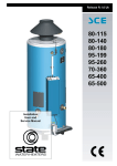
1
GSM/GPRS/GPS Tracker
(LDW-103B)
User Manual
Version 1.4
Please read this manual carefully before attempting installation and online activation.
Pictures are for indication and illustration purposes only.
Chapter I Preface
1. 1 General
LDW-103B represents the perfect combination of GSM, GPRS and GPS
technologies. This model, with precise dimensions and compact appearance,
expresses the advanced workmanship in the GSM and GPS field and is the typical
design combing communication products and GPS services. As a professional
security and positioning company, we will provide you with more and better products
and services. Before use, please spend several minutes reading this user’s manual in
order to understand operation details and obtain better services.
1.2 Notices
1) Please read carefully this user’s manual and always use correct operation
methods to prevent any possible errors.
2) This user’s manual is for reference only. If some contents and operation steps
are inconsistent with those for the actual product, the latter will prevail.
3) The defaulted password of this product is 000000. GPS Tracker LDW-103B is
a perfect combination of GSM, GPRS and GPS. Small size and simple appearance are
the typical design of the combination of telecommunication products and GPS
positioning products. Advanced technology and craft in GSM and
GPS area are embodied in this product.
Chapter II About the Device
LDW-103B is remote vehicle positioning device comprising GPS and
GSM/GPRS modules. Based upon the GPS satellite, it shall offer you precise
positioning information on dynamic conditions. The remote vehicle positioning
device shall send longitudinal and latitudinal coordinates to the authorized cell phone,
which can be utilized by you to position and manage your own vehicles.
2.1 Major Functions of the Product
Vehicle Positioning and Tracking
Real-time polling and sending back GPS positioning information (which
contains longitude, latitude, speed and direction) and the vehicle information to the
service platform www.gps288.com, displaying vehicle’s real-time condition of the
vehicles.
Trace Playback
Related information such as the passed trace, speed and time and so on of the
vehicles in the past period can be replayed.
Historical Data Backup
In the data base, vehicle’s driving time, trace and speed etc. can be conserved in
one day or more. In order to keep the response speed of the data service, the system
shall automatically transfer the current database into historical database at regular
intervals.
Anti-burglary and Anti-robbery
In case of emergency situation, driver can press the SOS button for sending the
message to pre-set number to ask for help.
Message Dispatching
If necessary, the administrator can send messages to the driver’s mobile-phone to
dispatch, direct the vehicle.
2.2 Components
2.2.1 Built-in GPS module and GSM module
Instructions: the red line connects to the power positive; the black line connects
to the
power negative.
2.2.2 Internet Service Center: www.gps288.com.
2.3 Product Features
● Individual or fleet GPS polling
● Worldwide use
● Supports GSM frequencies 850/900/1800/1900MHz
● High-sensitivity, latest technology and the most advanced GPS chip
● Can accurately position even if with weak signal
● Can work effectively in limited space such as the remote and narrow places;
● compact size, easy for hiding
●Low energy consumption
●Remote oil cutoff
● Fast signal capturing
● supports two modes: text message polling and GPRS trace tracking
● Alarm function
● Vibration alarm
2.4 Product Specifications
2.4.1 Technical specifications
GSM FREQUENCY
850/900/1800/1900MHz
GPS CHIPS
SIRF 4
GPRS
Class 12, TCP/IP build in GSM MODULE
GPS SENSITIVITY
-159dBm
GPS ACCURACY
10m (2D RM)
GSM ACCURACY
50-200m
SPEED ACCURACY
0.1m/s
COLD STATUS
-38s
WARM STATUS
-32s
HOT STATUS
-2s
MAXIMUM ALTITUDE
18000m
HIGHEST SPEED
515m/s
ACCELERATION
OF <4g
GRAVITY
SIZE
72.00(L) x 38.0(W) x17.0(H) mm
WEIGHT
50g
2.4.2 Others
WORKING TEMPERATURE
HUMIDITY
VOLTAGE
CURRENT
STANDARD
AVERAGE
CURRENT
LED
-20--+70℃
20%---80%RH
7—30v DC
~60mA(12v DC)
<80MA
~35mA(24v DC)
LED indicate GPS、GSM working status or other
condition
2.4.3 The indication of the terminal state
Red LED------Power/Running-state
The state of the light
Always light
Meaning
Indicate the power supply, normal working
Flash
No light
state
Abnormal working state
Out of power or internal fault
Green LED------GPS Signal
The state of the light
Always light
No light
Meaning
GPS signal received normally
GPS signal close
Blue LED------GSM Signal
The state of the light
Always light
No light
Meaning
GSM signal OK/Call coming
GSM signal close
2.4.4 Accessories
2.5 Installation
2.5.1 Preparation
1.Check the product: open the package, and check the terminal model and
fittings.If there is something wrong, please contact the distributor.
2 Select the SIM card: it must insult a GSM SIM card, and the selection of SIM
card must follow the distributor's suggestion.
3 Install the SIM card. Firstly, open the cover of the terminal, remove the cover
on the slot for SIM card; secondly, insult the card into the slot with the metal side in
the bottom; thirdly, fasten the slot(do as the following instruction); finally, recover the
terminal and lock the shell tightly with three screws.
Tips :
Don't insult the terminal SIM card up-side-down.
You must open the GPRS function provided by the terminal SIM;
If your SIM card has been setup, but it requires you to input SIM PIN, please
close the SIM PIN function under the instruction written in the user manual.
Make sure the sufficient money to pay for the terminal SIM card charge
Check the GPRS network connection with your mobile phone.
2.5.2 The selection and installation of the terminal
This terminal is a product with GPS polling, a kind of high-tech product, you'd
better to install it with the help of professional companies or workers authorized by
the distributor.
Please install it according to the following order, don't revise it, or supply power
for the terminal.
There are two ways to install the terminal: hidden installation and open
installation. Hidden installation is suitable for the application of the terminal in the
specialized vehicle. While open installation is suitable for the adoption of the terminal
in the provisional vehicle.
2.5.1.1 The hidden installation should be completed by the professional
institution authorized by the distributor.
1) To avoid the thief’s destruction, the terminal should be installed in a hidden
place. Suggestions are as follow:
Hidden beneath the decoration board below the front windshield.
Hidden around the front panel (with a surface made of non-metal materials )
Hidden beneath the decoration board under the back windshield.
2) don't put the terminal together with the emission sources, such as the parking
radar system, alarms and other vehicle-carried communication terminals.
3) You can fix the terminal with the cable tie, or glue it with wide strong sponge
double-sided tapes.
4) As there are GSM and GPS antennae furnished inside the terminal, it must make
sure the reception side of GSP upward(facing the sky), besides there is no shelter
caused by metal articles.
Attention:
If there is a metal insulation or a heating level glued in the windshield, it will
reduce the efficiency of GPS signal reception, and lead to change the installation
position of the terminal due to the malfunction of GPS.
2.5.1.2 AS for the open installation, at first it should glue the soft robber magnet
(in the fitting picture ) on the decoration below the front windshield; then put the
terminal on the magnet and fix it.
Attention:
If you have no soft robber magnet, please purchase after connect with the
distributor.
Installation steps (caution: the following installation should be made without
power supply, otherwise it will be dangerous)
Wire for cutting off oil/ circuit of the tracker
White wire connects relay feet 86; 85 feet
to 12 V DC postive, 87a feet and 30 feet are
in series in the supply power circuits.
2.6 The cable connection of the terminal
1. The standard power supply is 7V-30V, the red line connects to the power
positive, while the black line connects to the power negative.
2. The negative end should connect the ground or the metal alone, don't connect
with other ground cord.
3. After connecting the power cord, please pull the power cord plug near the
terminal, and supply power for it after installation.
4. As for the hidden installation, the connection cords for the power should be
the main power cord provided by the original manufacturer (in the fitting pictures),
the red end connects with the fuse box (contains 2A FUSE), which can avoid the short
circuit and over current.
5. As for the open installation, the connection cords for the power should be the
lighter power cord provided by the original manufacturer (in the fitting pictures), the
lighter, which has 2A FUSE can avoid the short circuit and over current.
Remind:
Please contact your distributor if you don’t have the lighter power cord.
2.7 Terminal working
1. Starting up:The terminal automatically starts up with power connecting, the red
indicator on means the power supply normally. Working normally, the red indicator
will keeps on; the blue GPS indicator will always bright means GPS polling standy
already; the green indicator shows GSM connecting successfully.
2.Working exception: after working for some time, the red indicator light flashes, blue
GPS Light off, means that GPS is off or failure, GSM indicator not on shows that
GSM fails to receive signal, please see the troubleshooting method to eliminate the
problem.
3. Powering off: Pull the plug, and the terminal will be powering off after cutting off
the electricity.
2.8 Side key function
In normal light conditions, press the side button 3S, then the current location
information will be sent back to the center number
2.9Terminal failure recovery
2.9.1 Disconnecting between terminal and service center:
Firstly, please checks the three lights of terminal, if there is no conditions for
observation, please call the terminal SIM card number using a mobile phone, and
according to instruction to judge the terminal state.
● If not connected, and suggests that the terminal cannot be connected or temporarily
out of service .
Terminal may not be covered by the GSM signal, or in weak for signal such as the
basement, please drive to some place covered by GSM net.
● If not connected, and suggests insufficient funds of the terminal or shut down.,
please recharge for this SIM card.
● If it is connected and there is the "beep" sound.
Terminal SIM card is installed correctly and has remaining, please contact the
operator of this SIM card to check whether the card has opened GPRS ; or you can
also use the phone browser, enter your favorite Web site to see whether can open
the Web page. Otherwise, it should not open GPRS service, please contact
network operators to open it for you.
● If not connected, and the terminal has turned off
At this point, must call vehicle back to check the working status of the terminal,
dealing with the following steps:
a) Check the red indicator, if not light, check the terminal connections at the fuse or
power supply terminal; it also can be measured with a millimeter to check the 2P
main power line voltage, if the voltage is normal, then please remove the
terminal machine and send it back to the original dealer for maintenance service.
b) If the red power indicator is constantly on, green light for GSM is not on, then
please check SIM card is properly installed, if the installation has no problem
and please change for another SIM card to use.
2.9.2 When the GPS signal reception is abnormal:
Please drive to a more open area to locate. It takes one or two minutes for the
first time. If it does not locate, please check the installation location of the
terminal, which is usually installed in the place without metallic shelter.
2.9.3 When the GSM signal reception is abnormal:
Please check whether the terminal's SIM card is correctly installed; or the
place may not be covered by GSM signal (such as in the basement), please
drive to the places covered by signal.
2.9.4 At the moment connecting power:
If the red light is not on, check the insurance of power lines to see whether the
wire is fused, if it is fused, please contact your dealer for the same model
FUSE and exclude internal fault of the terminal before reuse.
2.10 Location queries
Global Services Platform Website: www.gps288.com
Chapter III SMS command format
Note: All the setup below can be only made by Center number.
Super User Setup
Set the new center number and new password by SMS through mobile phone. If the
setup is successful, the module will send a reply with ‘Config OK the Main User and
Password Is Reset To 13689645010 (center no.): 123456 (new password)’.
Format: #CJML# SN code # new password (6 digits) # Center number#
SN code pls checking it with backside of produt.
Example: #CJML#886600000633#000000#13689645010#
Note: Center number must be a mobile phone number, telephone number will
not work.
Center Number Setup
Set the center number by SMS through mobile phone. If the setup is successful, the
sender will receive “CONFIG OK The main user is: 13286689393” from the tracker
Format: #710# former password # new password (6 digits) #center number#
For example: #710#000000#000000#13689645010#
Note: All alarming information thereafter including SOS, low power, electronic
fence etc. will be sent to this number. 000000 is the default password.
APN (Access Point Name) Setup
Set APN by SMS through mobile phone. If the setup is successful, the sender will
receive “CONFIG OK” from the tracker
Format: #802 #GSM provider name #APN # Log user name # Log password #
The default APN is CMNET, if the APN doesn’t have login user name and password,
it can be set 0.
Example 1: #802#Chinamobile#CMNET#0#0#
APN is CMNET, no login user name, no login password
Example 2: #802#CHINAMOBILE#CCDLEN#QIUXIA.21#RX0000#
APN is CCDLEN; the login user name is QIUXIA.21 and login password is
RX0000.
Note: The default APN of this product is CMNET.
Server connection Setup
Format: #803# domain name or IP address # port number#
This command is used to set GPRS center server address, which could be fixed IP
number. After the setup is successful, the module will send a reply with ‘config ok,
the ip server is 59.188.20.67:8545’.
Example: #803#59.188.20.67#8545#
Setup via domain name:
Example: #803#www.gps288.com#8545#
Regular Upload Interval Setup
The defaulted factory upload time interval of this device is 10 seconds for getting the
point and uploading one point location information. The user could change such
parameter according to actual demand.
Format: #730# sampling interval #
The value of sampling interval from 10 seconds to 3600 seconds
For example: #730#30#
Note: The parameter “30” indicates getting and uploading one point location
information every 30s.
Vehicle Defense Setup
Note: You need to open the vehicle defense first, then you can use the vibration Alarm,
or you cannot use vibration Alarm.
1) Open vehicle defense
Format: #911#
After sending command successfully, the tracker will return a message “config OK
The Auto Alert Is: On”.
2) Close vehicle defense
Format: #910#
After sending command successfully, the tracker will return a message “config OK
The Auto Alert Is: Off”.
Vibration Alarm Setup
Format: #ZDBJ # sensitivity (1-15)# alarm mode (0,1 )#
Sensitivity “1” is the most sensitive and of course “15” is the most insensitive.
Alarm mode”0’ indicates vibration alarm is closed.
Alarm mode”1” indicates the device will alarm you through calls or SMS.
Note: SMS will be sent only when the device is online on the tracking system.
For example: If you set #ZDBJ#1#1#, the device will send you back ”Config OK The
Vibrate Warning Is: 1 1”
That means that the tracker is in a most sensitive status and alarm by calls.
Cut oil supply by SMS
Format: #DY# password # state #
The value of state is “0” and “1”,”1” is cut off oil, “0” is restore oil
Example: #DY#000000#1#
For safety, this command will be function when the speed less than 5KM/h
After sending command successfully, the tracker will return a message “config OK”
and cut oil supply of the vehicle.
Over-speed Alarm Setup
Format: #CSBJ# speed limit (km/h) # state #
The value of state is “0” and “1”,”1” means “open over-speed alarm”, “0” means
“close over-speed alarm”.
Example: #CSBJ#80#0#
After sending command successfully, the tracker will return a message “config OK
The Warning Speed Is: 80 Off”.
Time Zone Setup
Format: #896# E or W # time zone #
The value of state is “E” and “w”, ”E” means “eastern time zone”, “W” means
“western time zone”.
Example: #896#E#8#
After sending command successfully, the tracker will return a message “config OK Set
Current time zone as: E8”.
Note: The default time zone is GMT+8. So you need recover it to GMT 0 first with
command “#896#w#8#”. Then you can set your time zone accordingly.
Open GPS Signal
Note: Center number can send this command to open GPS. The tracker will begin to
work with GPS signal. There is still GPS signal even the tracker is shutdown.
Format: #810#
After sending command successfully, the tracker will return a message “config OK”.
Note: The default GPS signal state is open.
Close GPS Signal
Note: Note: Center number can send this command to close GPS. The GPS module
will stop working and in this mode, there will be less power consumption. There is
still no GPS signal even the tracker is shutdown.
Format: #811#
After sending command successfully, the tracker will return a message “config OK”.
Pre-stored numbers Setup
Format:#711#password#phone number1# phone number2# phone number3# phone
number4#
Note: phone no. 4 is the voice monitor no. and it cannot be the same one as center
number or any other pre-stored numbers. (Only this number can do voice monitor.)
For example:You want to set four stored numbers
#711# 000000#13567892314#13892341600#13625678900#13625678901#
The new numbers will replace the old numbers, and it will send confirmation to the
sender if the password is right….CONFG OK. Note: 13625678901 is the voice
monitor no., only this number can make voice monitor.
SOS button(Emergency call button)
In case of emergency, please press SOS button over 3 seconds, center number will
receive a call and SMS.
Note: SMS will be sent only when the device is online on the tracking system.
Device Setup inquiry
Format: #902#password#
Example: #902#000000#
After sending command successfully, the tracker will return a message “Settings: The
Main User Is: 13689645010 The Auto Alert Is: Off Low Battery Alert Is On The
Vibrate Warning Is :On The Alert Call Is :Off The Warning Speed is :Off”.
Remote Restart
Format: #90382#password#
Example: #90382#000000#
After sending command successfully, the tracker will return a message “Config OK
The Machine Will Restart!”
Restore factory settings
Format: #HFSZ#
Example: #HFSZ#
After sending command successfully, the tracker will return a message “Config OK
Device Has Been Reset To Factory Setting”
Chapter Ⅳ SMS & Platform Tracking
4.1MS location inquiry
There is no need for Center number to add the password to inquiry. Other numbers
need to add the password to inquiry.
4.1.1 Address tracking
Format: #666#password#
For example you send #666#000000# to the tracker, you will get a reply SMS as
follow:
SN: 886600000525
No.106, Sanlian Road, Longhua Town, Bao’an District, Shenzhen, China.
Notes: Only when the device is online on the tracking system, it will send you
back this SMS information.
4.1.2 Longitude & latitude tracking
Format: #888#password#
For example you send #888#000000# to the tracker, you will get a reply SMS with
link.
http//map.google.com/?q=22.677327N,114.120738E SPEED: 000.0
Date: 12-05-28
Time: 15:52:04
IMEI: 353509000924608
Visit the link by your phone or computer; you will know the name of the location
in detail.
When there is no GPS signal, you will get a repay SMS as follow:
MCCMNC: 460010 LAC: d1e3 CELLID: 2535
4.2 Tracking on platform
Please visit www.gps288.com or www.track188.com for online real-time tracking and
fleet management.
For details, please refer to our tracking system user manual.
Notes
1. This non-waterproof equipment, please be sure to have waterproof
bag.
2. This equipment has to work with GSM network.
3. Please ensure that there are enough expenses in SIM card in order to
avoid the inconvenience of using.
4. This equipment cannot work in the power failure state and outside the
service areas, even if the registered users.
5. This equipment supports GPS and GSM/GPRS double positioning,
regarding as the same with the GPS positioning results.
6. Please use this equipment in the legal areas. The consequences of any
violation of the law will be undertaken by the users themselves.