1
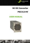
DC/DC CONVERTER PSC305-HV USER MANUAL UM_PSC305HV_E_R3.0.doc DC/DC Converter PSC305-HV User Manual Page 2 (20) Notes to this manual ATTENTION! Read this manual very carefully before installing and commissioning the specified module. This manual is a part of the delivered module. Familiarity with the contents of this manual is required for installing and operating the specified module. The rules for prevention of accidents for the specific country and the general safety rules in accordance with IEC 364 must be observed. The function description in this manual corresponds to the date of publishing. Technical changes and changes in form and content can be made at any time by the manufacturer without notice. There are no obligations to update the manual continually. The module is manufactured in accordance with applicable DIN and VDE standards such as VDE 0106 (part 100) and VDE 0100 (part 410). The CE marking on the module confirms compliance with EU standards 2006-95-EG (low voltage) and 2004-108-EG (electromagnetic compatibility) if the installation and operation instructions are followed. Supplier: FAX Email Internet ELTEK VALERE DEUTSCHLAND GmbH GB Industrial Schillerstraße 16 D-32052 Herford + 49 (0) 5221 1708-210 + 49 (0) 5221 1708-222 [email protected] http://www.eltekvalere.com Changes and errors excepted. 2009. ELTEK VALERE DEUTSCHLAND GmbH. All rights reserved. ©2009. ELTEK VALERE DEUTSCHLAND GmbH. UM_PSC305HV_E_R3.0.doc DC/DC Converter PSC305-HV User Manual Page 3 (20) The current revision status of this user manual is the following: Revision: Date: 3.0 2010-01-19 Revision Description of change Writer Date 00 First edition RTH 2007-11-06 01 Correction of output voltage values RTH 2008-01-28 RTH 2008-02-14 RTH 2009-01-06 02 1.0 Section “Commissioning” reworked, minor text modifications, default values corrected Minor layout & text modifications, new revision status numbering (X.X) introduced, index of figures inserted. 2.0 Default values in section 4.6 changed, minor text modifications. RTH 2009-03-24 3.0 Section 4.7 "Setting of the output voltage/threshold values" inserted, "Technical Specifications" completed. RTH 2010-01-19 ©2009. ELTEK VALERE DEUTSCHLAND GmbH. UM_PSC305HV_E_R3.0.doc DC/DC Converter PSC305-HV User Manual Page 4 (20) Table of Contents 1A. Safety Instructions.......................................................................................................................5 1B. Electric Waste Disposal ...............................................................................................................5 2. General information ........................................................................................................................6 3. Type range/equipment..................................................................................................................6 3.1 Main data .....................................................................................................................................................................6 3.2 Available options and assembly equipment ......................................................................................................7 3.3 Front view/front side LED panel ............................................................................................................................8 3.4 Rear side connection ................................................................................................................................................9 3.5 Cooling and air flow direction ............................................................................................................................. 10 3.6 Communication interface..................................................................................................................................... 10 4. Handling.......................................................................................................................................... 11 4.1 Storage ...................................................................................................................................................................... 11 4.2 Commissioning ........................................................................................................................................................ 11 4.3 Output power diagram .......................................................................................................................................... 12 4.4 LED indications........................................................................................................................................................ 13 4.5 Monitoring................................................................................................................................................................. 13 4.6 Default values .......................................................................................................................................................... 14 4.7 Setting of the output voltage/threshold values ............................................................................................ 14 5. Maintenance.................................................................................................................................. 15 6. Troubleshooting ........................................................................................................................... 15 7. Technical specifications............................................................................................................ 16 7.1 Dimensional drawings: .......................................................................................................................................... 17 8. Notes ............................................................................................................................................... 18 Index of figures Figure 1) DC/DC power rack fully equipped ...................................................................................................................7 Figure 2) Fan rack .................................................................................................................................................................7 Figure 3) Front view..............................................................................................................................................................8 Figure 4) Rear side connector............................................................................................................................................9 Figure 5A) Rack airflow, convection-cooled ............................................................................................................... 10 Figure 5B) Rack airflow with fan rack........................................................................................................................... 10 Figure 6) Output power diagram.................................................................................................................................... 12 Figure 7) Screenshot “PC software for CAN-Dongle” ............................................................................................... 14 Figure 8) Module dimensions .......................................................................................................................................... 17 ©2009. ELTEK VALERE DEUTSCHLAND GmbH. UM_PSC305HV_E_R3.0.doc DC/DC Converter PSC305-HV User Manual Page 5 (20) 1A. Safety Instructions Warning! Because several components of operating electrical modules are charged by dangerous voltage, the improper handling of electrical modules may be the cause of accidents involving electrocution, injury, or material damages. Operation and maintenance of electrical modules must be performed by qualified skilled personnel such as electricians in accordance with EN 50110-1 or IEC 60950. Install the module only in areas with limited access to unskilled personnel. Before starting work, the electrical module must be disconnected from mains. Make sure that the module is earthed. Do not touch connector pins as they can be charged with dangerous voltage up to 30 seconds after disconnection. Only spare parts approved by the manufacturer must be used. 1B. Electric Waste Disposal Separate collection is the precondition to ensure specific treatment and recycling of waste electrical and electronic equipment and is necessary to achieve the chosen level of protection of human health and the environment. In the case of waste disposal of your discarded equipment we recommend to contact a waste management company. ©2009. ELTEK VALERE DEUTSCHLAND GmbH. UM_PSC305HV_E_R3.0.doc DC/DC Converter PSC305-HV User Manual Page 6 (20) 2. General information The PSC305 is a module with rear side connectors and is designed to be mounted in an assembly set 19’’ sub rack according to section 3.2. Due to its state-of-the-art circuit design, the unit has very low losses and therefore very compact dimensions, low weight and a very high power density. The PSC305 can be used as electrically isolated DC power supply. The nominal output power per unit is 480 W. Several units can be switched in parallel to increase the system output power or to build redundant power supply systems (n + 1-principle) 3. Type range/equipment Type Designation Article Code Nominal Output Voltage Nominal Output Current PSC305-HV/24-20 201-005-747.00 24VDC 20ADC PSC305-HV/48-10 201-005-757.00 48VDC 10ADC PSC305-HV/60-8 201-005-767.00 60VDC 8.0ADC PSC305-HV/110-4.4 201-005-777.00 110VDC 4.4ADC PSC305-HV/220-2.2 201-005-787.00 220VDC 2.2ADC 3.1 Main data DC input voltage range: 90 to 275 VDC DC input current: 4.9ADC @110VDC/2.5ADC @220VDC Nominal output power: 480W Specific data: See section 7. ©2009. ELTEK VALERE DEUTSCHLAND GmbH. UM_PSC305HV_E_R3.0.doc DC/DC Converter PSC305-HV User Manual Page 7 (20) 3.2 Available options and assembly equipment Designation Material Code DC/DC power rack DDR PSC305-HV (assembly set 19’’ sub rack 4U incl. backplane) for six DC/DC converters PSC305 (single input/output connection for each module) 202-305-607.00 Cover plate (with handle) to cover unused PSC slots, 3U; RAL 7035 881-MEC-BPL.03.14.B Fan rack (recommended) 102-308-FR1.HV02 CAN dongle, incl. software; necessary to change the output voltage value/internal default values of the DC/DC converter. 880-CAN-DNG.00 Figure 1) DC/DC power rack fully equipped with Figure 2) Fan rack (recommended) six DC/DC converters PSC305 ©2009. ELTEK VALERE DEUTSCHLAND GmbH. UM_PSC305HV_E_R3.0.doc DC/DC Converter PSC305-HV User Manual Page 8 (20) 3.3 Front view/front side LED panel The PSC305-HV is equipped with the following four LED indicators: INPUT OK OUTPUT OK Vout> ALARM For more information about the LED indicators, see section 4.4. Two captive screws are used for each module to secure it to the subrack (components of the module) Figure 3) Front view ©2009. ELTEK VALERE DEUTSCHLAND GmbH. UM_PSC305HV_E_R3.0.doc DC/DC Converter PSC305-HV User Manual Page 9 (20) 3.4 Rear side connection Socket outlet (DC-Input, DC-Output & Signals): Pin assignment of the rear side connector: Pin Function 2b (-) Output 5b 8b 11b (+) Output 13a CAN-CVpp 13c (-) output voltage sense link 14a CAN-H 14c CAN-L 15a (+) 20 V free floating 15c CAN-CVCC 16a AGND 16c (-) 20V free floating 17a Hardwarecoding CODE2 17c Hardwarecoding CODE1 18a General alarm NC 18c General alarm COM 19a General alarm NO 19c - 20a - 20c (+) output voltage sense link 22b PE 25b 28b (+) DC input 31b (-) DC input Figure 4) Rear side connector (shown from the rear side of the module). ©2009. ELTEK VALERE DEUTSCHLAND GmbH. UM_PSC305HV_E_R3.0.doc DC/DC Converter PSC305-HV User Manual Page 10 (20) 3.5 Cooling and air flow direction Normally the DC/DC converters PSC305 integrated in the serial power rack are convection-cooled. The cooling air flows through the perforated cover (see figure 5A). REMARK: We recommend the use of the optional fan rack (see section 3.2), because in most applications there is no enough space for sufficient natural airflow inside the power supply cabinet. The fans are temperature-controlled and r.p.m.-monitored. The air flow is from bottom to top (see figure 5B). To provide sufficient air flow, a minimum space (see item “A” in figures 5A) and 5B) of 2 U (approx. 90 mm) is required between the top of the sub rack and the roof of the power supply cabinet as well as an unobstructed supply of air. Figure 5A) Rack airflow, convection-cooled Figure 5B) Rack airflow with fan rack 3.6 Communication interface The DC/DC converter PSC305 is equipped with a serial data interface in accordance with the Controller Area Network (CAN) specification. The CAN-Bus connection is integrated in the rear side connector. Several modules in a system or parallel connection can be monitored through the CAN-Bus by a central DC controller unit UPC3S. Following parameters of a specific DC/DC converter unit can be monitored: Output voltage Output current Module temperature Module status ©2009. ELTEK VALERE DEUTSCHLAND GmbH. UM_PSC305HV_E_R3.0.doc DC/DC Converter PSC305-HV User Manual Page 11 (20) 4. Handling 4.1 Storage The modules must be stored in a dry, dust free room with a storage temperature in accordance with the specific technical data (see section 7). 4.2 Commissioning Note: Before commissioning the module make sure that the input voltage corresponds to the input voltage range of the unit as specified on the type plate and that the output voltage of paralleled units matches. 1. 2. 3. 4. 5. 6. Carefully unpack the unit Fill the rack beginning with the left slot. Put the unit into an empty slot. Carefully slide in the unit until the module connector touched the backplane connector. Increase the force until the unit fits in completely. Avoid using too much force. If the unit does not fit in, begin again at Step 3. Secure the unit using the two captive screws (M3x12) provided with the module. Note: The PSC305 serially is equipped with an internal output side decoupling diode. This ensures hot plug-in capability of the unit and enables the operator to add modules under operating conditions. Note: But if the module is to be removed it previously must be switched off by the external input fuse! Caution: After switching off the module the internal capacitors are still fully charged. Do not touch connector pins as they can still be charged with dangerous voltage after disconnection. ©2009. ELTEK VALERE DEUTSCHLAND GmbH. UM_PSC305HV_E_R3.0.doc DC/DC Converter PSC305-HV User Manual Page 12 (20) 4.3 Output power diagram The output characteristic of the PSC305 is a power limited IV characteristic curve in accordance with DIN 41772/DIN 41773. For modules in parallel operation mode, a load balance of approximately ±10% is attained due to a sloping output voltage line (-1% at 100% Inom). The module is continuously short-circuit proof due to constant current control. Output power diagram (example PSC305-HV/48-10): Figure 6) Output power diagram ©2009. ELTEK VALERE DEUTSCHLAND GmbH. UM_PSC305HV_E_R3.0.doc DC/DC Converter PSC305-HV User Manual Page 13 (20) 4.4 LED indications Functions of front panel LED indicators LED Colour Function green Input voltage ok (criterion: Vi= 80 VDC to 300 VDC) green Vout ok (criterion: Vout ≥85% of adjusted value)* red Vout > (criterion: Vout ≥ adjusted operating threshold)* red General fault**: Vin incorrect, Vout incorrect, module overtemperature and short circuit *For the output voltage threshold values (factory-set), see section 4.6 **The module is equipped with an isolated signalling contact (normally open contact). The maximum load is 60VDC/500 mA. The contact is time-delayed and reacts after approximately 10 seconds. 4.5 Monitoring Monitoring functions Monitored values Criteria Function DC input voltage Input voltage less than 80V; higher 300V DC output voltage Output voltage higher than the adjusted operating threshold* Module temperature Heat sink temperature ≥80°C The module automatically switches off. The module automatically switches off (self locking). The module manually must be restarted. The module automatically switches off. It automatically switches on when the heat sink cools down to ≤70°C. *For the output voltage threshold values (factory-set), see section 4.6 ©2009. ELTEK VALERE DEUTSCHLAND GmbH. UM_PSC305HV_E_R3.0.doc DC/DC Converter PSC305-HV User Manual Page 14 (20) 4.6 Default values The following factory-set default values are stored in PSC305 modules: Default values 24V version 48V version 60V version 110V version 220V version Vo (VDC) 24.0 48.0 60.0 110.0 220.0 V> (VDC) 25.2 50.4 63.0 115.5 231.0 Iconst (ADC) 20.0 10.0 8.0 4.4 2.2 V< (VDC) 22.8 45.6 57.0 104.5 209.0 4.7 Setting of the output voltage/threshold values The output voltage/threshold values individually can be set within the scope of the output voltage adjustment range (see section 7) using a CAN dongle and PC software (see section 3.2 “Available Options and Assembly Equipment”). A specific manual is available on request. Figure 7) Screenshot “PC software for CAN-Dongle” ©2009. ELTEK VALERE DEUTSCHLAND GmbH. UM_PSC305HV_E_R3.0.doc DC/DC Converter PSC305-HV User Manual Page 15 (20) 5. Maintenance In general, the module is maintenance free. A yearly inspection with following checks is recommended checking the following: Mechanical inspection Removal of dust and dirt, especially on radiator surfaces Check for internal dust or humidity Attention! Dust combined with moisture or water may influence or destroy the internal electronic circuits. Dust inside the unit can be blown out with dry compressed air. The interval between the checks depends on ambient conditions of the installed module. 6. Troubleshooting Symptom No output voltage Possible reason Is the input voltage present? PSC305 module plugged in securely? Incorrect polarity of input voltage? Short circuit at the output? Corrective action → Check → Check → Check → Check Deviation of the output voltage → Reduce the load Is the unit operating in power limitation mode due to overload? If an external sensor lead is used for the output voltage, is the connection faultless? → Check If the module still does not work even though all checks have been done, contact your sales agent or the ELTEK VALERE DEUTSCHLAND service department. ©2009. ELTEK VALERE DEUTSCHLAND GmbH. UM_PSC305HV_E_R3.0.doc DC/DC Converter PSC305-HV User Manual Page 16 (20) 7. Technical specifications Type designation PSC305-HV/24-20 PSC305-HV/48-10 PSC305-HV/60-8 PSC305-HV/110-4.4 PSC305-HV/220-2.2 Article code 201-005-747.00 201-005-757.00 201-005-767.00 201-005-777.0 201-005-787.00 DC input: DC input voltage range 90 - 275VDC Input current 4.9ADC @ 110VDC/2.5ADC @ 220VDC Efficiency ≥89% Internal input fusing 10A (6.3x32mm) DC output: Nominal output voltage (factory set)* 24VDC 48VDC 60VDC 110VDC 220VDC Nominal output current @ nominal output voltage 20.0ADC 10.0ADC 8.0ADC 4.4ADC 2.2ADC Nominal output power 480W Adjustable output voltage range* 19 - 36VDC 38 - 75VDC 48 - 88.5VDC 87 - 160VDC 172 - 313VDC Factory set output over voltage threshold* V> (105% Vnom) 25.2VDC 50.4VDC 63.0VDC 115.5VDC 231.0VDC Factory set output under voltage threshold* V< (95% Vnom) 22.8VDC 45.6VDC 57.0VDC 104.5VDC 209.0VDC *The output voltage/threshold values individually can be set within the scope of the output voltage adjustment range using a CAN dongle and PC software. Voltage ripple ≤20mVpp/ ≤20mVpp ≤20mVpp ≤≤100mVpp ≤≤200mVpp Psophometric acc. to CCITT-A ≤1.8mV ≤1.8mV ≤1.8mV - - Dynamic accuracy of the charge voltage ≤3% Vnom at load changes between 10%-90%-10% Inom; transient time ≤1.5ms Short circuit protection continuously short-circuit proof; 1 x Inom Parallel operation yes (max. 24 units with DC controller unit UPC3S); current balance approx. ±10% Inom Internal decoupling at the output yes; active low loss decoupling circuit in the negative output line Internal output fuse 40A 25A 20A 10A 5A Standard Features: LED signalling Operation (green), Vo OK (green), Vo> (red), Alarm (red) Isolated signalling contact “General fault”; maximum load: 60 VDC/500 mA Communications interface CAN- Bus, proprietary protocol Environmental: Ambient temperature Operation: -20°C to +55°C; storage: -40°C to +85°C; output power derating to 100W depending on ambient temperature and cooling Climatic conditions according to IEC 721-3-3 class 3K3/3Z1/3B1/3C2/3S2/3M2 Max. installation altitude ≤1500m Audible noise ≤30dBA ©2009. ELTEK VALERE DEUTSCHLAND GmbH. UM_PSC305HV_E_R3.0.doc DC/DC Converter PSC305-HV User Manual Page 17 (20) Mechanical: Type of construction 1/6 x 19’’, 3U Cooling Convection cooling, bottom to top airflow (forced cooling recommended) Connections DC input, DC output and signalization: DIN41612-M-connector Dimensions (W/H/D) 71/128/285mm Minimum installation depth 390 mm plus 25.5mm handle depth (in combination with an assembly set 19’’ sub rack) Weight approx. 2.2 kg Type of enclosure / Protection class IP20 (front panel)/1 Colour Front panel: RAL 7035; print: neutral, RAL 9005 approx. 2.2 kg approx. 2.2 kg approx. 2.2 kg approx. 2.2kg Compliances: CE conformity yes Compliance to safety standards EN60950-1; VDE0100 T410; VDE0110; EN50178; EN60146 Compliance to EMC standards EN55011/22 class “B“; EN61000-4 T2-5 7.1 Dimensional drawings: Figure 8) Module dimensions ©2009. ELTEK VALERE DEUTSCHLAND GmbH. UM_PSC305HV_E_R3.0.doc DC/DC Converter PSC305-HV User Manual Page 18 (20) 8. Notes ©2009. ELTEK VALERE DEUTSCHLAND GmbH. UM_PSC305HV_E_R3.0.doc DC/DC Converter PSC305-HV User Manual Page 19 (20) Notes ©2009. ELTEK VALERE DEUTSCHLAND GmbH. UM_PSC305HV_E_R3.0.doc Supplier: FAX Email Internet ELTEK VALERE DEUTSCHLAND GmbH GB Industrial Schillerstraße 16 D-32052 Herford + 49 (0) 5221 1708-210 + 49 (0) 5221 1708-222 [email protected] http://www.eltekvalere.com 2009. ELTEK VALERE DEUTSCHLAND GmbH. All rights reserved.